Eaton 93PM 50-100 kW SIAC-T and 50-100 kW SIAC-TB Installation and peration Manual P-164000370—Rev 04 v
LLiisstt ooff FFiigguurreess
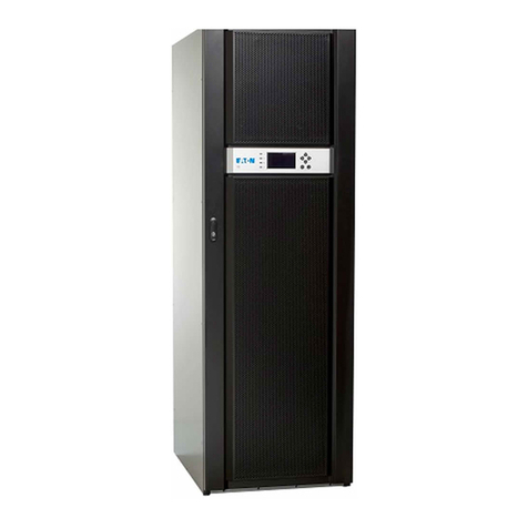
Figure 1. 93PM 50 kW SIAC-T or 93PM 50 kW SIAC-TB attached to an Eaton 93PM 50 kW UPS .................................2
Figure 2. 93PM 100 kW SIAC-T attached to an Eaton 93PM 100 kW UPS ............................................................... 3
Figure 3. Eaton 93PM 100 kW SIAC-TB attached to an Eaton 93PM 100 kW UPS.....................................................4
Figure 4. Eaton 93PM 50 kW UPS with 93PM 50 kW SIAC-T, 93PM 50 kW UPS with 93PM 100 kW SIAC-TB, or
93PM 100 kW UPS with 93PM 100 kW SIAC-T Dimensions (Front View) ................................................. 12
Figure 5. Eaton 93PM 50 kW UPS with 93PM 50 kW SIAC-T, 93PM 50 kW UPS with 93PM 100 kW SIAC-TB, or
93PM 100 kW UPS with 93PM 100 kW SIAC-T Dimensions (Top and Bottom Views) ................................. 13
Figure 6. Eaton 93PM 50 kW UPS with 93PM 50 kW SIAC-T, 93PM 50 kW UPS with 93PM 100 kW SIAC-TB, or
93PM 100 kW UPS with 93PM 100 kW SIAC-T Center of Gravity ........................................................... 14
Figure 7. Eaton 93PM 100 kW UPS with 93PM 100 kW SIAC-TB Dimensions (Front View)....................................... 17
Figure 8. Eaton 93PM 100 kW UPS with 93PM 100 kW SIAC-TB Dimensions (Top and Bottom Views)....................... 18
Figure 9. Eaton 93PM 100 kW UPS with 93PM 100 kW SIAC-TB Center of Gravity................................................. 19
Figure 10. Eaton 93PM UPS Cabinet with SIAC-T or SIAC-TB Front and Rear Floor Mounting Bracket Mounting
Dimensions ................................................................................................................................ 21
Figure 11. 93PM 50 kW SIAC-T or 93PM 50 kW SIAC-TB attached to 50 kW UPS as Shipped on Pallet......................... 29
Figure 12. Eaton 93PM 100 kW SIAC-T attached to 100 kW UPS as Shipped on Pallet .............................................. 30
Figure 13. Eaton 93PM 100 kW SIAC-TB attached to 100 kW UPS as Shipped on Pallet ............................................ 31
Figure 14. Line-Up-and-Match Wiring Access Locations...................................................................................... 34
Figure 15. 93PM 50 kW SIAC-T, 93PM 50 kW SIAC-TB, and 93PM 100 kW SIAC-T Conduit Landing Wire Entry
Locations ................................................................................................................................... 36
Figure 16. 93PM 50 kW SIAC-T and 93PM 100 kW SIAC-T Output Power and Ground Terminal Locations .................... 37
Figure 17. 93PM 50 kW SIAC-T and 93PM 100 kW SIAC-T with MIS Output Power Terminal Detail............................. 38
Figure 18. 93PM 50 kW SIAC-T and 93PM 100 kW SIAC-T without MIS Output Power Terminal Detail ........................ 39
Figure 19. 93PM 100 kW SIAC-TB Conduit Landing Wire Entry Locations............................................................... 41
Figure 20. 93PM 50 kW SIAC-TB Bypass Input Power, Output Power, and Ground Terminal Locations ........................ 42
Figure 21. 93PM 100 kW SIAC-TB Bypass Input Power, Output Power, and Ground Terminal Locations....................... 43
Figure 22. 93PM 50 kW SIAC-TB and 93PM 100 kW SIAC-TB Bypass Input Power Terminal Detail.............................. 44
Figure 23. 93PM 50 kW SIAC-TB Output Power Terminal Detail ........................................................................... 45
Figure 24. 93PM 100 kW SIAC-TB Output Power Terminal Detail ......................................................................... 45
Figure 25. SIAC-T Interface Terminal Location .................................................................................................. 48
Figure 26. SIAC-T Interface Terminal Detail ...................................................................................................... 49
Figure 27. Eaton 93PM 50 kW SIAC-TB Interface Terminal Location...................................................................... 50
Figure 28. 93PM 100 kW SIAC-TB Interface Terminal Location ............................................................................ 51
Figure 29. SIAC-TB Interface Terminal Detail .................................................................................................... 52
Figure 30. MOB and Pull Chain Wiring ............................................................................................................ 55
Figure 31. UPS MBP Interface Terminal Location .............................................................................................. 56
Figure 32. UPS MBP Interface Terminal Detail.................................................................................................. 57
Figure 33. Two-Breaker (no MIS) Sidecar Integrated Accessory Cabinet-Tie (SIAC-T) Internal Oneline........................... 61
Figure 34. Three-Breaker (with MIS) Sidecar Integrated Accessory Cabinet-Tie (SIAC-T) Internal Oneline ...................... 62
Figure 35. Four-Breaker (with MIS and MBP) Sidecar Integrated Accessory Cabinet-Tie Bypass (SIAC-TB) Internal
Oneline...................................................................................................................................... 62


