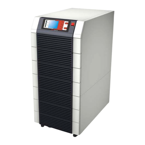
Eaton 93PR 500 kW UPS
User's and Installation Guide
viii
List of Figures
Figure 2-1: Eaton 93PR UPS................................................................................................................................................... 7
Figure 2-2: Position Indication................................................................................................................................................. 8
Figure 2-3: 93PR 500kW UPS Wiring Diagram ......................................................................................................................10
Figure 2-4: Path of current through the UPS in Double Conversion Mode............................................................................12
Figure 2-5: Path of current through the UPS in Energy Saver System ..................................................................................13
Figure 2-6: Path of current through the UPS in Battery Mode...............................................................................................14
Figure 2-7: Path of current through the UPS in Bypass Mode..............................................................................................15
Figure 3-1: UPS Cabinet Clearances. See Table
3-3
.............................................................................................................. 21
Figure 3-2: UPS Dimensions................................................................................................................................................. 23
Figure 3-3: UPM Dimensions ............................................................................................................................................... 24
Figure 3-4: straighten the securing tabs............................................................................................................................... 31
Figure 3-6: Remove cushioning ............................................................................................................................................ 31
Figure 3-5: Remove wooden box.......................................................................................................................................... 31
Figure 3-7: Remove the shipping bracket ............................................................................................................................. 32
Figure 3-8: Fork into Position ................................................................................................................................................ 32
Figure 3-9: Instruction for Removing the UPM Module Packaging....................................................................................... 33
Figure 4-1: Gland Plate and Connector Locations................................................................................................................. 35
Figure 4-2: Separate Battery Configurations ........................................................................................................................ 37
Figure 4-3: Common Battery Configurations ........................................................................................................................ 38
Figure 4-4: Connections of the EPO Switch ......................................................................................................................... 39
Figure 4-5: Principle of Paralleled UPS Systems................................................................................................................... 43
Figure 4-6: Communication Interfaces ................................................................................................................................. 44
Figure 4-7: Simplified CAN and Pull-Chain Wiring for Parallel UPP System .......................................................................... 45
Figure 4-8: CAN and Pull-Chain Wiring for Parallel UPS........................................................................................................ 45
Figure 5-1: Communication interfaces................................................................................................................................. 46
Figure 5-2: Gigabit Network Card ......................................................................................................................................... 47
Figure 5-3: Environmental Monitoring Probe generation 2 (EMPG2) ................................................................................... 47
Figure 5-4: Industrial Gateway Card...................................................................................................................................... 48
Figure 5-5: PowerXpert UPS MiniSlot card (PXGMS UPS) ................................................................................................... 48
Figure 5-6: Relay Card-MS.................................................................................................................................................... 49
Figure 5-7: Industrial relay card............................................................................................................................................. 49
Figure 6-1: UPS Controls and Indicators............................................................................................................................... 51
Figure 6-2: UPS Color Touch screen Control Panel (Typical).................................................................................................. 52
Figure 6-3: Parts of the Touch Screen ................................................................................................................................... 54
Figure 6-4: Sign In or Password Request Screen ................................................................................................................. 54
Figure 6-7: UPM Module Location........................................................................................................................................ 63
Figure 6-8: Double Conversion Mode................................................................................................................................... 66
Figure 6-9: Maintenance Bypass Mode................................................................................................................................ 67
