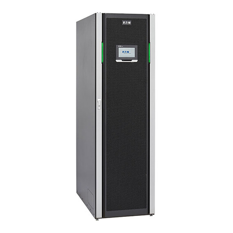
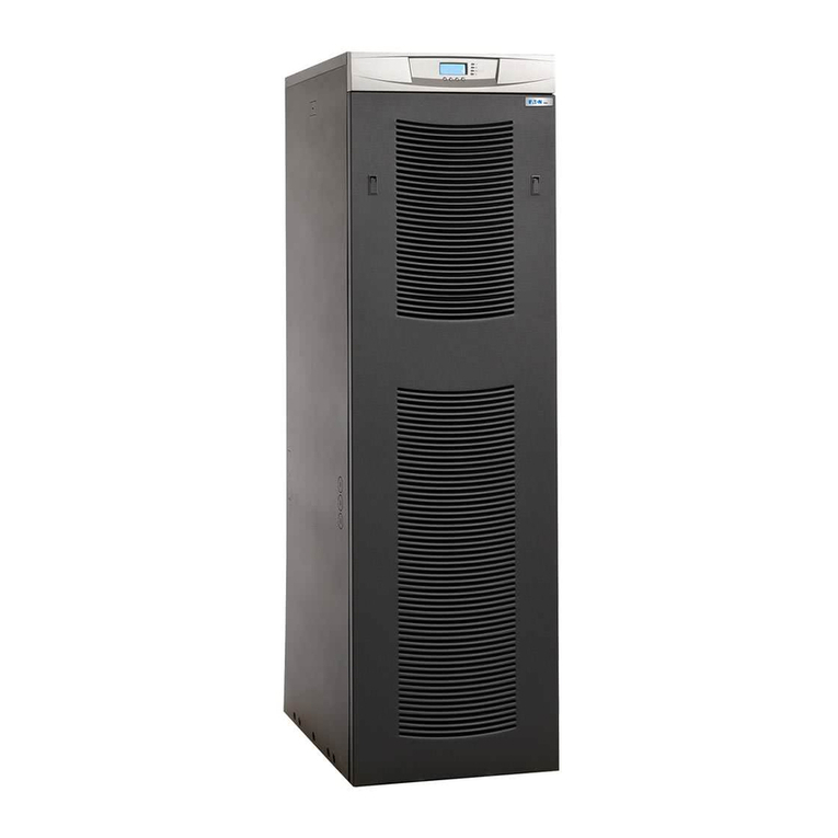
Eaton Power Xpert 9395 UPS Plus 1 User manual

p/n: 164201710
Revision 14
225–275 kVA
Installation and Operation Manual
Power Xpert™9395 UPS Plus 1 UPS

Eaton reserves t e rig t to c ange specifications wit out prior notice. Eaton, Powerware, Powerware Hot Sync, PowerXpert, and X-Slot
are registered trademarks. IBM and AS/400 are registered trademarks of International Business Mac ines Corporation. Modbus is a
registered trademark of Sc neider Automation. National Electrical Code and NEC are registered trademarks of National Fire Protection
Association, Inc. All ot er trademarks are property of t eir respective companies. All ot er trademarks are property of t eir respective
companies.
©Copyrig t 2022 Eaton, Raleig , NC, USA. All rig ts reserved. No part of t is document may be reproduced in any way wit out t e
express written approval of Eaton.
IMPORTANT SAFETY INSTRUCTIONS - SAVE THESE INSTRUCTIONS
This manual contains important instructions that you should follow during installation and maintenance
of the UPS. Please read all instructions before operating the equipment and save this manual for
future reference.
CONSIGNES DE SÉCURITÉ IMPORTANTES — CONSERVER CES INSTRUCTIONS
Ce manuel comporte des instructions importantes que vous êtes invité à suivre lors de toute
procédure d installation et de maintenance de la UPS. Veuillez consulter entièrement ces instructions
avant de faire fonctionner l équipement et conserver ce manuel afin de pouvoir vous y reporter
ultérieurement.
This is a product for restricted sales distribution to informed partners (EN/IEC 62040-2). Installation
restrictions or additional measures may be needed to prevent electromagnetic disturbances.

Dear Customer,
On behalf of everyone at Eaton, we thank you for partnering
with us, and trusting us to maintain your business continuity
and preventing downtime at your facility.
Our suite of backup power, power distribution and power
management products are designed to protect you from a host
of threats including power outages, surges, lighting strikes, and
enable you to monitor and control your power infrastructure.
We trust that your Eaton 9395 Uninterruptible Power Supply
system, will deliver high quality, reliable backup power for your
business, and we are committed to your success.
Please read this Installation and Operation Manual, which
details the installation, and operation processes for your
uninterruptible power supply system.
Thank you for choosing Eaton!

Eaton End-User License Agreement
IMPORTANT, READ CAREFULLY. THIS END USER LICENSE AGREEMENT (THE “AGREEMENT”) IS
A BINDING CONTRACT BETWEEN YOU, THE END-USER (THE “LICENSEE”) AND EATON
INTELLIGENT POWER LIMITED, IRELAND, OR ONE OF ITS AFFILIATES (“EATON” OR
“LICENSOR”). BY OPERATING THIS UNINTERRUPTIBLE POWER SUPPLY (UPS) PRODUCT
INCLUDING SOFTWARE EMBEDDED IN IT (FIRMWARE), YOU, THE LICENSEE, ARE AGREEING TO
BE BOUND BY THE TERMS, CONDITIONS, AND LIMITATIONS OF THIS AGREEMENT. READ THE
TERMS AND CONDITIONS OF THIS AGREEMENT CAREFULLY BEFORE, INSTALLING OR
OPERATING THE PRODUCT. IF YOU DO NOT AGREE TO THE TERMS OF THIS AGREEMENT,
PROMPTLY RETURN THE UNUSED PRODUCT TO EATON.
1.0 DEFINITIONS
1.1 Documentation. “Documentation” means the user guides and manuals for the installation and
use of the UPS, whether made available over the internet, provided in CD-ROM, DVD, hard copy or
other form.
1.2 Firmware. “Firmware” means software programs that are embedded in the product for which
Licensee is granted a license hereunder, the Documentation therefore and, to the extent available,
Updates thereto. The Firmware is licensed hereunder in object code (machine readable) form only
except that certain software programs may include limited portions in source code (human-readable)
form.
1.3 U date. “Update” means a subsequent release of the Firmware, if and when developed by
Eaton. An Update does not include any release, new version, option, or future product, which Eaton
licenses separately.
2.0 FIRMWARE LICENSE
2.1 Ownershi . Eaton or its third party licensors retains all title, copyright and other proprietary rights
in, and ownership of the Firmware regardless of the media upon which the original or any copy may
be recorded or fixed.
2.2 License Grant. Eaton grants to Licensee a limited, revocable, non-exclusive, non-assignable
license to use the Firmware in conjunction with the operation of the product to which the Firmware
pertains or other products as described by Eaton in the Documentation. Licensee does not acquire
any rights, express or implied, other than those expressly granted in this Agreement.
2.3 Restrictions and Requirements. Licensee will not, nor will it permit others to, modify, adapt,
translate, reverse engineer, decompile, or disassemble the Firmware or any component thereof
(including the Documentation), or create derivative works based on the Firmware (including the
Documentation), except to the extent such foregoing restriction is prohibited by applicable law or
applicable open source license to, and only to, any open source software component that is
incorporated into the Firmware (if any). Copyright laws and international treaties protect the Firmware,
including the Documentation. Unauthorized copying of the Firmware, the Documentation or any part
thereof, is expressly prohibited. For avoidance of doubt, Eaton does not grant Licensee a license to
any of Eaton’s brands, logos, designs, trade dress, service marks, trademarks, domain names or trade
names, in whole or in part. Licensee agrees to install or allow installation of all corrections of
substantial defects, security patches, minor bug fixes and updates, including any enhancements, for
the Firmware in accordance with the instructions and as directed by Eaton.
2.4 Transfer and Assignment Restrictions. Licensee will not sell, resell, assign, lease, sublicense,
encumber, or otherwise transfer its interest in this Agreement or in the Firmware, or the
Documentation in whole or in part, or allow any other person or entity, including any parent or
subsidiary of Licensee or other subsidiary of Licensee’s parent, to copy, distribute, or otherwise
transfer the Firmware without the prior written consent of Eaton. Licensee may transfer the Firmware
directly to a third party only in connection with the sale of the Eaton product in which it is installed.

3.0 TERMINATION
3.1 Termination. This Agreement and the license granted hereunder automatically terminates if
Licensee breaches any provision of this Agreement. Eaton may terminate this license at any time with
or without cause.
3.2 Effect of Termination. Immediately upon termination of this Agreement or the license granted
hereunder, Licensee will cease using the product. The parties’ rights and obligations under the
following sections of this Agreement will survive termination of this Agreement: Article 1.0, Section
2.1, Section 2.3, Section 2.4, Article 3.0, Article 4.0 and Article 5.0.
4.0 INFRINGEMENT AND WARRANTIES
4.1 Infringement. If Licensee learns of a threat, demand, allegation, or indication that the UPS with its
firmware infringes or misappropriates any third party intellectual property rights (including but not
limited to any patent, copyright, trademark, trade dress, or trade secret) (“Intellectual Property
Claim”), Licensee will notify Eaton promptly of such claim. Eaton may, in its sole discretion, elect to
assume sole control of the defense and settlement of said Intellectual Property Claim and Licensee
will provide reasonable information and assistance to Eaton for the defense of such claim.
4.2 Disclaimer of Warranties. THE FIRMWARE IS PROVIDED “AS IS” WITHOUT WARRANTY OF
ANY KIND, . EATON DOES NOT WARRANT THAT THE FIRMWARE WILL BE ERROR-FREE OR
SECURE FROM UNAUTHORIZED ACCESS. THE LICENSEE EXPRESSLY ACKNOWLEDGES THAT
TO THE EXTENT PERMITTED BY APPLICABLE LAW, THE USE OF THE PRODUCT IS AT LICENSEE’S
SOLE RISK.
5.0 GENERAL PROVISIONS
5.1 U date Policy. Eaton may from time to time, but has no obligation to, create Updates of the
Firmware or components thereof.
5.2 Limitation on Liability. NOTWITHSTANDING ANY PROVISION OF THIS AGREEMENT TO THE
CONTRARY, LICENSEE EXPRESSLY UNDERSTANDS AND AGREES THAT EATON, ITS AFFILIATES,
AND ITS LICENSORS, WILL NOT BE LIABLE FOR: (A) ANY DIRECT, INDIRECT, INCIDENTAL,
SPECIAL, CONSEQUENTIAL OR EXEMPLARY DAMAGES WHICH MAY BE INCURRED BY
LICENSEE OR ANY THIRD PARTY, HOWEVER CAUSED AND UNDER ANY THEORY OF LIABILITY.
THIS WILL INCLUDE, BUT NOT BE LIMITED TO, ANY LOSS OF PROFIT (WHETHER INCURRED
DIRECTLY OR INDIRECTLY), ANY LOSS OF GOODWILL OR BUSINESS REPUTATION, ANY LOSS
OF DATA SUFFERED, COST OF PROCUREMENT OF SUBSTITUTE GOODS OR SERVICES, OR
OTHER INTANGIBLE LOSS; (B) ANY LOSS OR DAMAGE WHICH MAY BE INCURRED BY LICENSEE
OR ANY THIRD PARTY. THESE LIMITATIONS ON EATON’S LIABILITY WILL APPLY WHETHER OR
NOT EATON HAS BEEN ADVISED OF OR SHOULD HAVE BEEN AWARE OF THE POSSIBILITY OF
ANY SUCH LOSSES ARISING. TO THE EXTENT PERMITTED BY LAW, THE TOTAL LIABILITY OF
EATON, ITS AFFILIATES, AND ITS LICENSORS, FOR ANY CLAIMS UNDER THESE TERMS,
INCLUDING FOR ANY IMPLIED WARRANTIES, IS LIMITED TO THE AMOUNT PAID FOR THE UPS.
THIS SECTION 5.2 STATES EATON’S ENTIRE LIABILITY AND LICENSEE’S SOLE AND EXCLUSIVE
REMEDY UNDER THIS AGREEMENT, AND IS SUBJECT TO ALL LIMITATIONS STATED IN SECTION
4.2.
5.3 Notices. All notices required to be sent hereunder will be in writing and will be deemed to have
been given when mailed by first class mail to the address shown below:
LICENSE NOTICES:
Eaton Intelligent Power Limited
Eaton House,
30 Pembroke Road,
Dublin 4, D04 Y0C2,
Ireland

5.4 Severability. If any provision of this Agreement is held to be invalid or unenforceable, the
remaining provisions of this Agreement will remain in full force.
5.5 Waiver. The waiver by either party of any default or breach of this Agreement will not constitute a
waiver of any other or subsequent default or breach. Failure to enforce or delay in enforcing any
provision of this Agreement will not constitute a waiver of any rights under any provisions of this
Agreement.
5.6 Entire Agreement. This Agreement constitutes the complete agreement between the parties and
supersedes all prior or contemporaneous agreements or representations, written or oral, concerning
the subject matter of this Agreement. This Agreement may not be modified or amended except in a
writing specifically referencing this Agreement and signed by a duly authorized representative of each
party. No other act, document, usage or custom will be deemed to amend or modify this Agreement.
The Firmware, or portions thereof, may also be subject to additional paper or electronic license
agreements. In such cases, the terms of this Agreement will be supplemental to those in the
additional agreements, to the extent not inconsistent with the additional agreements. If a copy of this
Agreement in a language other than English is included with the Firmware or Documentation, it is
included for convenience and the English language version of this Agreement will control.
5.7 Heirs, Successors, and Assigns. Each and all of the covenants, terms, provisions and
agreements herein contained will be binding upon and inure to the benefit of the parties hereto and, to
the extent expressly permitted by this Agreement, their respective heirs, legal representatives,
successors and assigns.
5.8 Ex ort Restrictions. Licensee agrees to comply fully with all relevant export laws and regulations
of the United States and all other countries in the world (the “Export Laws”) to assure that neither the
Firmware nor any direct product thereof are (I) exported, directly or indirectly, in violation of Export
Laws; or (ii) are intended to be used for any purposes prohibited by the Export Laws. Without limiting
the foregoing, Licensee will not export or re-export the Firmware: (i) to any country to which the U.S.
has embargoed or restricted the export of goods or services (see http://www.treasury.gov/resource-
center/sanctions/ Programs/Pages/ Programs.aspx), or to any national of any such country, wherever
located, who intends to transmit or transport the Firmware back to such country; (ii) to any end user
who Licensee knows or has reason to know will utilize the Firmware in the design, development or
production of nuclear, chemical or biological weapons; or (iii) to any end-user who has been prohibited
from participating in U.S. export transactions by any federal agency of the U.S. government.
5.9 U.S. Government Restricted Rights. The Firmware is a “commercial item” as that term is
defined at 48 C.F.R. § 2.101, consisting of “commercial computer software” and “commercial
computer software documentation”, as such terms are used in 48 C.F.R. § 12.212, and is provided to
the U.S. Government only as a commercial end item. Consistent with 48 C.F.R. § 12.212 and 48 C.F.
R. §§ 227.7202-1 through 227.7202-4, all U.S. Government End Users acquire the Firmware with only
those rights set forth herein. Contractor/manufacturer is Eaton Corporation, 1000 Eaton Boulevard,
Cleveland, Ohio 44122.
5.10 Third Party Intellectual Pro erty Rights. The Firmware may contain components (including
open source software components) that are owned by third parties (“Third Party Licensors”) and are
provided with, incorporated into, or embedded in, the Firmware pursuant to license arrangements
between Eaton and such third parties. Third Party Licensor components in the Firmware are not
licensed or warranted under the terms of this document, but are instead subject to the Third Party
Licensors’ license agreements. Licensee will not modify, delete, or obfuscate any copyright or other
proprietary rights notices of Third Party Licensors contained in the Firmware.
5.11 Indemnity. Licensee shall defend, indemnify and hold Eaton and its officers, directors,
employees, and agents harmless from and against all losses, damages, liabilities, claims, actions, and
associated costs and expenses (including reasonable attorneys’ fees and expenses) by reason of
injury or death to any person or damage to any tangible or intangible property arising or resulting from
the negligence or willful misconduct of the Licensee, its employees, contractors, or agents, in
connection with Licensee’s use of Firmware and Documentation. Licensee shall be responsible for
any breach of this Agreement by its officers, directors, employees, contractors, or agents. Licensee
shall defend, indemnify, and hold Eaton and its officers, directors, employees, and agents harmless
from and against any and all losses, damages, liabilities, claims, actions, and associated costs and
expenses (including reasonable attorneys’ fees and expenses) arising out of or in connection with any
breach of this Agreement.
5.12 O en Source Software. The Firmware may contain certain components owned by Eaton that
are provided with, incorporated into, linked to, or embedded in the Firmware that are subject to third
party open source licenses (“Eaton Open Source Components”). Eaton OpenSource Components are
subject to the open source licenses corresponding to the particular software component. To the
extent there are any conflicts between the terms of this Agreement and any open source license
corresponding to Eaton Open Source Components or additional obligations by such open sources
license that are not set forth in this Agreement, the terms of the open source license will control.
5.13 Confidentiality. Licensee acknowledges that confidential aspects of the Firmware (including any
proprietary source code) are a trade secret of Eaton, the disclosure of which would cause substantial
harm to Eaton that could not be remedied by the payment of damages alone and such confidential
aspects of the Firmware shall not be disclosed to third parties without the prior written consent of
Eaton. Accordingly, Eaton will be entitled to preliminary and permanent injunctive and other equitable
relief for any breach of this Section 5.13.
5.14 Note on JAVA Su ort. The Firmware may contain support for programs written in JAVA.
JAVA technology is not fault tolerant and is not designed, manufactured, or intended for use or resale
as online control equipment in hazardous environments requiring fail-safe performance, such as in the
operation of nuclear facilities, aircraft navigation or communications systems, air traffic control, direct
life support machines, or weapons systems, in which the failure of JAVA technology could lead
directly to death, personal injury, or severe physical or environmental damage. EATON DISCLAIMS
ALL DAMAGES INCLUDING DIRECT, INDIRECT AND CONSEQUENTIAL DAMAGES RELATING TO
THE FAILURE OF ANY SOFTWARE INCLUDING JAVA PROGRAMS AND/OR JAVA TECHNOLOGY.
5.15 Governing Law. This Agreement will be interpreted and enforced in accordance with the laws of
Ireland, without regard to choice of law principles. Any claim or suit with respect to this Agreement
shall be brought in the Courts of Ireland, unless mandatory law imposes otherwise.


Eaton Power Xpert 9395 UPS Installation and Operation Manual 164201710—Rev 14 ix
TTaabbllee ooff CCoonntteennttss
11 IInnttrroodduuccttiioonn ..................................................................................................................................................................................................................................................................................................11
1.1 UPS Standard Features ...............................................................................................................................1
1.1.1 Installation Features .............................................................................................................................. 1
1.1.2 Control Panel .......................................................................................................................................2
1.1.3 Customer Interface ...............................................................................................................................2
1.1.4 Advanced Battery Management...............................................................................................................3
1.1.5 Power Management Software................................................................................................................. 3
1.2 Options and Accessories ............................................................................................................................. 3
1.2.1 Integrated Battery Cabinets .................................................................................................................... 3
1.2.2 Field Installed UPM ...............................................................................................................................3
1.2.3 Maintenance Bypass Module .................................................................................................................. 3
1.2.4 Sync Control........................................................................................................................................3
1.2.5 Single-Feed Kit.....................................................................................................................................3
1.2.6 Separate Rectifier Input.......................................................................................................................... 3
1.2.7 Distributed Bypass System ..................................................................................................................... 4
1.2.8 Inherent Redundancy ............................................................................................................................4
1.2.9 Energy Saver System and High Alert Modes............................................................................................... 4
1.2.10 Harmonic Reduction System (HRS)......................................................................................................... 5
1.2.11 Variable Module Management System and High Alert Modes.......................................................................5
1.2.12 Monitoring and Communication .............................................................................................................5
1.3 Battery System .........................................................................................................................................6
1.4 Using This Manual .....................................................................................................................................6
1.5 Conventions Used in This Manual..................................................................................................................6
1.6 Symbols, Controls, and Indicators..................................................................................................................7
1.7 For More Information..................................................................................................................................7
1.8 Getting Help .............................................................................................................................................8
1.9 Warranty..................................................................................................................................................8
22 SSaaffeettyy WWaarrnniinnggss........................................................................................................................................................................................................................................................................................99
33 UUPPSS IInnssttaallllaattiioonn PPllaann aanndd UUnnppaacckkiinngg ........................................................................................................................................................................................................................ 1133
3.1 Creating an Installation Plan ........................................................................................................................ 13
3.2 Preparing the Site ..................................................................................................................................... 13
3.2.1 General Storage Requirements for UPS Equipment.................................................................................... 13
3.2.2 Environmental Considerations ............................................................................................................... 14
3.2.3 Installation Considerations .................................................................................................................... 14
3.2.4 UPS System Power Wiring Preparation ................................................................................................... 20
3.2.5 UPS System Interface Wiring Preparation ................................................................................................ 31
3.2.6 Distributed Bypass Power Wiring Preparation ........................................................................................... 33
3.3 Inspecting and Unpacking the UPS Cabinet .................................................................................................... 34

x Eaton Power Xpert 9395 UPS Installation and Operation Manual 164201710—Rev 14
44 UUPPSS SSyyssttee IInnssttaallllaattiioonn.............................................................................................................................................................................................................................................................. 3377
4.1 Preliminary Installation Information............................................................................................................... 37
4.2 Unloading the UPS Cabinet from the Pallet and Mechanical Installation ................................................................ 37
4.3 Battery System Installation ......................................................................................................................... 41
4.4 Distributed Bypass Tie Cabinet Installation ..................................................................................................... 41
4.5 Installing UPS External and Battery Power Wiring ............................................................................................ 41
4.5.1 2–Hole Barrel Lug Terminations to Bus Bar Installation ............................................................................... 42
4.5.2 External Power Wiring Installation .......................................................................................................... 42
4.5.3 Battery Power Wiring .......................................................................................................................... 51
4.6 Installing Interface Connections ................................................................................................................... 53
4.6.1 TB1, TB2, and TB3 Connections (Other than TB1 Battery Interface Connections).............................................. 53
4.6.2 TB1 Battery Interface Connections ......................................................................................................... 60
4.6.3 X-Slot Connections.............................................................................................................................. 61
4.7 Installing a REPO Switch ............................................................................................................................ 62
4.8 Installing Options, Accessories .................................................................................................................... 66
4.9 Initial Startup ........................................................................................................................................... 67
4.10 Completing the Installation Checklist........................................................................................................... 67
55 IInnssttaalllliinngg OOppttiioonnss aanndd AAcccceessssoorriieess.............................................................................................................................................................................................................................. 7711
5.1 Installing an Optional Powerware Hot Sync CAN Bridge Card ............................................................................. 71
5.2 Installing Distributed Bypass Control Wiring ................................................................................................... 74
5.3 Installing an Optional Remote Monitor Panel II ................................................................................................ 78
5.4 Installing an Optional Relay Interface Module II ............................................................................................... 81
5.5 Installing an Optional Supervisory Contact Module II ........................................................................................ 82
5.6 Accessory Mounting Dimensions................................................................................................................. 84
66 UUnnddeerrssttaannddiinngg UUPPSS OOppeerraattiioonn ............................................................................................................................................................................................................................................ 8899
6.1 UPS System Overview .............................................................................................................................. 89
6.2 Single UPS.............................................................................................................................................. 90
6.2.1 Modes.............................................................................................................................................. 90
6.2.2 Online Mode...................................................................................................................................... 90
6.2.3 Energy Saver System Mode.................................................................................................................. 91
6.2.4 Harmonic Reduction System (HRS) ........................................................................................................ 92
6.2.5 Variable Module Management System .................................................................................................... 92
6.2.6 Bypass Mode..................................................................................................................................... 93
6.2.7 Battery Mode..................................................................................................................................... 94
6.3 Single UPS System Oneline Configurations .................................................................................................... 95
6.4 Multiple UPS Distributed Bypass System..................................................................................................... 100
6.4.1 Multiple UPS Parallel System Modes .................................................................................................... 100
6.4.2 Online Mode – Distributed Bypass........................................................................................................ 101
6.4.3 Bypass Mode – Distributed Bypass....................................................................................................... 102
6.4.4 Battery Mode – Distributed Bypass....................................................................................................... 104
Table of Contents

Eaton Power Xpert 9395 UPS Installation and Operation Manual 164201710—Rev 14 xi
6.5 Multiple UPS Distributed Bypass System Oneline Configurations ..................................................................... 105
77 UUPPSS OOppeerraattiinngg IInnssttrruuccttiioonnss ..................................................................................................................................................................................................................................................110099
7.1 UPS Controls and Indicators...................................................................................................................... 109
7.1.1 Control Panel ................................................................................................................................... 110
7.1.2 Circuit Breakers................................................................................................................................ 110
7.2 Using the LCD Control Panel ..................................................................................................................... 110
7.2.1 Status Indicators............................................................................................................................... 112
7.2.2 System Events................................................................................................................................. 112
7.2.3 Using the LCD and Pushbuttons .......................................................................................................... 113
7.2.4 Using the Menu................................................................................................................................ 114
7.2.5 Mimic Screen .................................................................................................................................. 114
7.2.6 Display Menu Operation..................................................................................................................... 115
7.2.7 Load Off Screen ............................................................................................................................... 119
7.2.8 System Status Screen and Controls ...................................................................................................... 119
7.3 Single UPS Operation .............................................................................................................................. 121
7.3.1 Starting the UPS in Online Mode .......................................................................................................... 121
7.3.2 Enable Energy Saver System Mode from the UPS Command Menu ............................................................ 122
7.3.3 Disable Energy Saver System Mode from the UPS Command Menu ........................................................... 123
7.3.4 Start Energy Saver System High Alert Mode from the UPS Command Menu................................................. 123
7.3.5 Enable Variable Module Management System Mode from the UPS Command Menu...................................... 124
7.3.6 Disable Variable Module Management System Mode from the UPS Command Menu ..................................... 124
7.3.7 Start Variable Module Management System High Alert Mode from the UPS Command Menu .......................... 125
7.3.8 Starting the UPS in Bypass Mode ......................................................................................................... 125
7.3.9 Enable Energy Saver System Mode from the Bypass Command Menu ........................................................ 126
7.3.10 Disable Energy Saver System Mode from the Bypass Command Menu ...................................................... 126
7.3.11 Start Energy Saver System High Alert Mode from the Bypass Command Menu ........................................... 127
7.3.12 Enable Variable Module Management System Mode from the Bypass Command Menu ................................ 127
7.3.13 Disable Variable Module Management System Mode from the Bypass Command Menu ............................... 127
7.3.14 Start Variable Module Management System High Alert Mode from Bypass Command Menu .......................... 128
7.3.15 Starting the UPMs........................................................................................................................... 128
7.3.16 Starting a Single UPM ...................................................................................................................... 130
7.3.17 Transfer from Online to Bypass Mode ................................................................................................. 131
7.3.18 Transfer from Bypass to Online Mode ................................................................................................. 131
7.3.19 Transfer from Online to Bypass Mode and Shut Down UPMs ................................................................... 131
7.3.20 Single UPM Shutdown ..................................................................................................................... 132
7.3.21 Single UPM Restart ......................................................................................................................... 133
7.3.22 UPS and Critical Load Shutdown ........................................................................................................ 133
7.3.23 Charger Control .............................................................................................................................. 134
7.3.24 Using the UPS LOAD OFF Pushbutton or Command .............................................................................. 134
7.3.25 Using the Remote Emergency Power-off Switch ................................................................................... 135
7.4 Multiple UPS Distributed Bypass Operation.................................................................................................. 137
Table of Contents

xii Eaton Power Xpert 9395 UPS Installation and Operation Manual 164201710—Rev 14
7.4.1 Starting the Distributed Bypass System in Online Mode............................................................................ 137
7.4.2 Enable Energy Saver System Mode from the UPS Command Menu ............................................................ 138
7.4.3 Disable Energy Saver System Mode from the UPS Command Menu ........................................................... 138
7.4.4 Start Energy Saver System High Alert Mode from the UPS Command Menu................................................. 139
7.4.5 Enable Variable Module Management System Mode from the UPS Command Menu...................................... 139
7.4.6 Disable Variable Module Management System Mode from the UPS Command Menu ..................................... 140
7.4.7 Start Variable Module Management System High Alert Mode from the UPS Command Menu .......................... 140
7.4.8 Starting the Distributed Bypass System in Bypass Mode........................................................................... 140
7.4.9 Enable Energy Saver System Mode from the Bypass Command Menu ........................................................ 141
7.4.10 Disable Energy Saver System Mode from the Bypass Command Menu ...................................................... 142
7.4.11 Start Energy Saver System High Alert Mode from the Bypass Command Menu ........................................... 142
7.4.12 Enable Variable Module Management System Mode from the Bypass Command Menu ................................ 142
7.4.13 Disable Variable Module Management System Mode from the Bypass Command Menu ............................... 143
7.4.14 Start Variable Module Management System High Alert Mode from the Bypass Command Menu ..................... 143
7.4.15 Starting the UPS UPMs .................................................................................................................... 144
7.4.16 Starting a Single UPM ...................................................................................................................... 145
7.4.17 Transfer from Online to Bypass Mode ................................................................................................. 146
7.4.18 Transfer from Bypass to Online Mode ................................................................................................. 146
7.4.19 Transfer from Online to Bypass Mode and Shut Down UPMs ................................................................... 147
7.4.20 Single UPM Shutdown ..................................................................................................................... 147
7.4.21 Single UPM Restart ......................................................................................................................... 148
7.4.22 Single UPS Shutdown using Load Off.................................................................................................. 148
7.4.23 Single UPS Shutdown using UPM Shutdown ........................................................................................ 149
7.4.24 Single UPS Restart .......................................................................................................................... 150
7.4.25 UPS and Critical Load Shutdown ........................................................................................................ 151
7.4.26 Charger Control .............................................................................................................................. 152
7.4.27 Using the UPS LOAD OFF Pushbutton or Command .............................................................................. 152
7.4.28 Using the Remote Emergency Power-off Switch ................................................................................... 154
7.5 Color Touchscreen Control Panel ............................................................................................................... 154
7.6 Using the Color Touchscreen Control Panel.................................................................................................. 156
7.6.1 Status Indicators............................................................................................................................... 157
7.6.2 Using the Touch Screen ..................................................................................................................... 158
7.6.3 Using the Main Menu Buttons ............................................................................................................. 160
7.6.4 Power Maps Screen (Online Mode) ...................................................................................................... 161
7.6.5 Power Maps Screen (Bypass Mode) ..................................................................................................... 163
7.6.6 Command Confirmation Pop-Up........................................................................................................... 163
7.6.7 Meters Summary Screen.................................................................................................................... 164
7.6.8 Input, Bypass and Output Meters Screens ............................................................................................. 165
7.6.9 Input Meters Detail Screen ................................................................................................................. 167
7.6.10 Battery Meters Screens.................................................................................................................... 168
7.6.11 System Events Main Screen.............................................................................................................. 171
Table of Contents

Eaton Power Xpert 9395 UPS Installation and Operation Manual 164201710—Rev 14 xiii
7.6.12 User Log ....................................................................................................................................... 171
7.6.13 System Status Screen and Controls .................................................................................................... 173
7.6.14 Settings Screen .............................................................................................................................. 176
7.6.15 Configuration Options Screen ............................................................................................................ 176
7.6.16 Energy Advantage Architecture (EAA) Screen........................................................................................ 177
7.6.17 Statistics Basic Screen ..................................................................................................................... 179
7.6.18 ESS Comparison Screen ................................................................................................................... 180
7.6.19 UPS Module Map Screen.................................................................................................................. 180
7.6.20 System Overview Screen ................................................................................................................. 181
7.7 UPS Operation using the Color Touchscreen Control Panel.............................................................................. 182
7.7.1 Starting the UPS in Online Mode .......................................................................................................... 182
88 CCoo uunniiccaattiioonn ....................................................................................................................................................................................................................................................................................118855
8.1 X-Slot Cards .......................................................................................................................................... 185
8.2 eNotify Service ...................................................................................................................................... 186
8.2.1 eNotify Service Features .................................................................................................................... 186
8.2.2 Installing eNotify Service .................................................................................................................... 186
8.3 Power Management Software................................................................................................................... 186
8.4 Building Alarm Monitoring ........................................................................................................................ 187
8.5 General Purpose Relay Contact ................................................................................................................. 187
8.6 Remote Monitor Panel II .......................................................................................................................... 187
8.7 Relay Interface Module II ......................................................................................................................... 190
8.8 Supervisory Contact Module II................................................................................................................... 191
99 UUPPSS MMaaiinntteennaannccee..............................................................................................................................................................................................................................................................................119933
9.1 Important Safety Instructions .................................................................................................................... 193
9.2 Performing Preventive Maintenance ........................................................................................................... 194
9.2.1 DAILY Maintenance .......................................................................................................................... 194
9.2.2 MONTHLY Maintenance .................................................................................................................... 194
9.2.3 PERIODIC Maintenance ..................................................................................................................... 195
9.2.4 ANNUAL Maintenance....................................................................................................................... 195
9.2.5 BATTERY Maintenance...................................................................................................................... 196
9.3 Installing Batteries .................................................................................................................................. 196
9.4 Recycling the Used Battery or UPS............................................................................................................. 196
9.5 Maintenance Training .............................................................................................................................. 196
1100 PPrroodduucctt SSppeecciiffiiccaattiioonnss............................................................................................................................................................................................................................................................119977
10.1 Model Numbers ................................................................................................................................... 197
10.2 Specifications....................................................................................................................................... 197
10.2.1 UPS Input...................................................................................................................................... 197
10.2.2 UPS Output ................................................................................................................................... 198
10.2.3 UPS Environmental ......................................................................................................................... 198
Table of Contents

Eaton Power Xpert 9395 UPS Installation and Operation Manual 164201710—Rev 14 xv
LLiisstt ooff FFiigguurreess
Figure 1. Power Xpert 9395 Plus 1 UPS (225–275 kVA) Cabinet ............................................................................ 2
Figure 2. UPS Cabinet Dimensions (Front View) .............................................................................................. 16
Figure 3. UPS Cabinet Dimensions (Right Side View)........................................................................................ 17
Figure 4. UPS Cabinet Dimensions (Top View) ................................................................................................ 17
Figure 5. UPS Cabinet Dimensions (Bottom View) ........................................................................................... 18
Figure 6. UPS Cabinet Dimensions (Bottom View with Mounting Brackets)........................................................... 18
Figure 7. UPS Cabinet Center of Gravity ........................................................................................................ 19
Figure 8. Remote EPO Switch Dimensions .................................................................................................... 19
Figure 9. Power Xpert 9395 Plus 1 UPS (225–275 kVA) Cabinet as Shipped on Pallet .............................................. 36
Figure 10. Removing the Left Side Shipping Bracket .......................................................................................... 39
Figure 11. Removing the Right Side Shipping Bracket ........................................................................................ 40
Figure 12. Typical Bus Bar Barrel Lug Mounting – Hardware Assembly Sequence .................................................... 42
Figure 13. Conduit and Wire Entry Locations .................................................................................................... 44
Figure 14. Distributed Bypass Wiring Length.................................................................................................... 46
Figure 15. UPS Power Terminal Locations – Common Rectifier Feed..................................................................... 47
Figure 16. UPS Power Terminal Detail AA – Common Rectifier Feed ..................................................................... 48
Figure 17. UPS Power Terminal Locations – Separate Rectifier Feed ..................................................................... 49
Figure 18. UPS Power Terminal Detail AA – Separate Rectifier Feed ..................................................................... 50
Figure 19. UPM Rectifier Input Power Terminal Block Detail................................................................................ 50
Figure 20. UPS Power Terminal Detail BB – Common Battery .............................................................................. 52
Figure 21. UPS Power Terminal Detail BB – Separate Battery .............................................................................. 53
Figure 22. Interface Terminal Locations........................................................................................................... 55
Figure 23. Interface Terminal Detail................................................................................................................ 57
Figure 24. Typical Alarm Relay Connection....................................................................................................... 58
Figure 25. Terminal Blocks TB1, TB2, and TB3 Connector Assignments................................................................. 59
Figure 26. Typical Battery Interface Connection — Common Battery System .......................................................... 61
Figure 27. Typical Battery Interface Connection – Separate Battery System ............................................................ 61
Figure 28. X-Slot Communication Bays ........................................................................................................... 62
Figure 29. REPO Switch .............................................................................................................................. 63
Figure 30. Normally-Open REPO Switch Wiring ................................................................................................ 65
Figure 31. Normally-Closed REPO Switch Wiring .............................................................................................. 66
Figure 32. Normally-Closed and Normally-Open REPO Switch Wiring .................................................................... 66
Figure 33. Powerware Hot Sync CAN Bridge Card. ............................................................................................ 72
Figure 34. Powerware Hot Sync CAN Bridge Card Connections ........................................................................... 73
Figure 35. Distributed Bypass System CAN and Pull-Chain Simplified Interface Wiring .............................................. 75
Figure 36. Distributed Bypass System UPS CAN Wiring without MOBs ................................................................. 75
Figure 37. Distributed Bypass Pull-Chain Wiring without MOBs............................................................................ 76
Figure 38. Distributed Bypass Pull-Chain Wiring with MOBs ................................................................................ 77
Figure 39. Remote Monitor Panel II and Remote Monitor Panel II Terminal Locations ............................................... 79

xvi Eaton Power Xpert 9395 UPS Installation and Operation Manual 164201710—Rev 14
Figure 40. Remote Monitor Panel II, Relay Interface Module II, or Supervisory Contact Module II Wiring....................... 80
Figure 41. J1, J2, J3, and J4 15-Pin D-Sub Connectors ....................................................................................... 82
Figure 42. Supervisory Contact Module II Terminal Location. ............................................................................... 83
Figure 43. Supervisory Contact Module II TB2 .................................................................................................. 84
Figure 44. Remote Monitor Panel II Dimensions ............................................................................................... 85
Figure 45. Relay Interface Module II Dimensions .............................................................................................. 86
Figure 46. Supervisory Contact Module II Dimensions........................................................................................ 87
Figure 47. Main Elements of the UPS System ................................................................................................. 89
Figure 48. Path of Current Through the UPS in Online Mode................................................................................ 91
Figure 49. Path of Current Through the UPS in Bypass Mode............................................................................... 93
Figure 50. Path of Current Through the UPS in Battery Mode............................................................................... 94
Figure 51. UPS System – Common Rectifier Feed, Common Battery, Dual-Feed Configuration ................................... 96
Figure 52. UPS System – Common Rectifier Feed, Separate Battery, Dual-Feed Configuration ................................... 97
Figure 53. Plus 1 UPS System – Separate Rectifier Feed, Separate Battery, Dual-Feed Configuration ........................... 98
Figure 54. Simplified Dual-Feed UPS with Maintenance Bypass Panel ................................................................... 99
Figure 55. Path of Current through the UPSs in Online Mode – Distributed Bypass................................................. 102
Figure 56. Path of Current through the UPSs in Bypass Mode – Distributed Bypass................................................ 103
Figure 57. Path of Current through the UPSs in Battery Mode – Distributed Bypass................................................ 104
Figure 58. Typical Distributed Bypass System (1+1 and 2+0 Configurations) ......................................................... 106
Figure 59. Typical Distributed Bypass System (2+1 and 3+0 Configurations) ......................................................... 107
Figure 60. Typical Distributed Bypass System (3+1 and 4+0 Configurations) ......................................................... 108
Figure 61. UPS Controls and Indicators ......................................................................................................... 110
Figure 62. UPS Control Panel...................................................................................................................... 111
Figure 63. Parts of the LCD ........................................................................................................................ 113
Figure 64. Main Menu and Mimic Screen (Online Mode)................................................................................... 114
Figure 65. Load Off Screen......................................................................................................................... 119
Figure 66. Typical System Status Screen ....................................................................................................... 120
Figure 67. REPO Operation ........................................................................................................................ 137
Figure 68. UPS Color Touchscreen Control Panel Location (Typical)..................................................................... 155
Figure 69. UPS Color Touchscreen Control Panel (Typical)................................................................................. 156
Figure 70. Parts of the Touch Screen ........................................................................................................... 158
Figure 71. Sign In or Password Request Screen ............................................................................................. 159
Figure 72. Home Screen ........................................................................................................................... 160
Figure 73. Main Menu and Power Maps Screen (Online Mode) ......................................................................... 161
Figure 74. Output kVA Screen from Home Screen .......................................................................................... 161
Figure 75. Average Efficiency Screen from Home Screen................................................................................. 162
Figure 76. Consumption Screen from Home Screen........................................................................................ 162
Figure 77. Bypass Screen.......................................................................................................................... 163
Figure 78. Typical Command Confirmation Screen (Charger Off) ........................................................................ 163
Figure 79. Meters Summary Screen ............................................................................................................ 164
Figure 80. Input Meters Screen .................................................................................................................. 165
List of Figures

Eaton Power Xpert 9395 UPS Installation and Operation Manual 164201710—Rev 14 xvii
Figure 81. Bypass Meters Screen ............................................................................................................... 166
Figure 82. Output Meters Screen................................................................................................................ 166
Figure 83. Input Meters Detail Screen.......................................................................................................... 167
Figure 84. Select Source Screen ................................................................................................................. 168
Figure 85. Battery Meters Screen ............................................................................................................... 168
Figure 86. Battery Log Screen .................................................................................................................... 169
Figure 87. Battery Log Detail...................................................................................................................... 170
Figure 88. Battery Log Summary Screen ...................................................................................................... 170
Figure 89. System Events Screen ............................................................................................................... 171
Figure 90. User Log Screen ....................................................................................................................... 172
Figure 91. User Log Detail Screen ............................................................................................................... 172
Figure 92. System Status Screen ................................................................................................................ 173
Figure 93. Module Controls Screen ............................................................................................................. 174
Figure 94. Module Control Detail Screen ...................................................................................................... 174
Figure 95. Online Mode Metering Method Option Screen ................................................................................ 175
Figure 96. Bypass Mode Metering Method Option Screen ............................................................................... 175
Figure 97. Settings Screen ........................................................................................................................ 176
Figure 98. Configuration Options Screen ...................................................................................................... 176
Figure 99. Energy Advantage Architecture (EAA) Screen .................................................................................. 177
Figure 100. Disable ESS Screen ................................................................................................................... 178
Figure 101. HRS Metering Screen ................................................................................................................. 178
Figure 102. High Alert Timer Screen.............................................................................................................. 179
Figure 103. Statistics Basic Screen ............................................................................................................... 179
Figure 104. Statistics Data Detail Screen ........................................................................................................ 180
Figure 105. ESS Comparison Screen ............................................................................................................. 180
Figure 106. UPS Module Map Screen............................................................................................................. 181
Figure 107. System Overview Screen ............................................................................................................ 181
Figure 108. Optional X-Slot Cards .................................................................................................................. 185
Figure 109. Remote Monitor Panel II .............................................................................................................. 188
Figure 110. Relay Interface Module II ............................................................................................................. 190
Figure 111. Supervisory Contact Module II ...................................................................................................... 191
Figure 112. UPS Filter Locations ................................................................................................................... 195
List of Figures

Eaton Power Xpert 9395 UPS Installation and Operation Manual 164201710—Rev 14 xix
LLiisstt ooff TTaabblleess
Table 1. Storage Area Contaminants ............................................................................................................. 14
Table 2. UPS Cabinet Maximum Weights....................................................................................................... 15
Table 3. UPS Cabinet Clearances ................................................................................................................. 15
Table 4. Air Conditioning or Ventilation Requirements During Full Load Operation................................................... 16
Table 5. Input/Output Ratings and External Wiring Requirements for the Power Xpert 9395-275/225 and 9395-275/
275 – Common Battery................................................................................................................... 22
Table 6. Input/Output Ratings and External Wiring Requirements for the Power Xpert 9395-275/225 and 9395-275/
275 – Separate Battery ................................................................................................................... 24
Table 7. Separate Rectifier Input UPM Ratings and External Wiring Requirements for the Power Xpert 9395-275/225
and 9395-275/275 – Separate Battery ................................................................................................ 26
Table 8. Neutral Bonding Jumper Wire Size (Four Wire Only).............................................................................. 26
Table 9. UPS Cabinet Power Cable Terminations for the Power Xpert 9395-275/225 and 9395-275/275....................... 26
Table 10. Supplied Wiring Terminal Hardware................................................................................................... 27
Table 11. Recommended Installation Parts and Tools (Not Supplied by Eaton) ......................................................... 27
Table 12. Separate Rectifier Input UPM Power Cable Terminations for the Power Xpert 9395-275/225 and 9395-275/
275............................................................................................................................................. 28
Table 13. Power Cable Conduit Requirements .................................................................................................. 29
Table 14. Recommended Input Circuit Breaker Ratings ...................................................................................... 30
Table 15. Separate Rectifier Input Recommended Input Circuit Breaker Ratings ...................................................... 30
Table 16. Recommended Bypass, Output, and MOB Circuit Breaker Ratings .......................................................... 31
Table 17. Recommended DC Input Circuit Breaker Ratings – Common Battery........................................................ 31
Table 18. Recommended DC Input Circuit Breaker Ratings – Separate Battery ........................................................ 31
Table 19. TB1, TB2, and TB3 Interface Connections .......................................................................................... 56
Table 20. REPO Wire Terminations ................................................................................................................ 64
Table 21. Powerware Hot Sync CAN Bridge Card Interface Connections ................................................................ 73
Table 22. CAN Bridge Card Wiring Terminations................................................................................................ 75
Table 23. Pull-Chain Wiring Terminations ......................................................................................................... 76
Table 24. Pull-Chain Wiring Terminations with MOBs ......................................................................................... 78
Table 25. RMP II, RIM II, or SCM II Wiring Terminations ..................................................................................... 80
Table 26. J1 through J4 Interface Connectors................................................................................................... 81
Table 27. Status Indicators ......................................................................................................................... 112
Table 28. Display Function Menu Map .......................................................................................................... 114
Table 29. Display Menu Operation ............................................................................................................... 115
Table 30. Typical System Status Messages.................................................................................................... 120
Table 31. Command Menu Operation ........................................................................................................... 120
Table 32. Status Indicators......................................................................................................................... 157
Table 33. Security Levels and Functions ....................................................................................................... 159
Table 34. Display Function Menu Map.......................................................................................................... 160
Table 35. RMP II Status Indicators................................................................................................................ 189
Table 36. Customer Interface Connectors...................................................................................................... 190
Table of contents
Other Eaton UPS manuals

Eaton
Eaton Power Xpert Plus 1 User manual

Eaton
Eaton 9PX3K3U User manual

Eaton
Eaton 9E1000i User manual

Eaton
Eaton Protection Station 650 User manual

Eaton
Eaton 9PX EBM 240V User manual

Eaton
Eaton 5E650i User manual

Eaton
Eaton BladeUPS Series User manual

Eaton
Eaton Powerware 9395 User manual

Eaton
Eaton 9910 User manual

Eaton
Eaton Power Xpert 9395P-1100/1100 User manual

Eaton
Eaton 9E User manual

Eaton
Eaton 93E 30ITC User manual

Eaton
Eaton Powerware 9155 User manual

Eaton
Eaton Powerware 9125 User manual

Eaton
Eaton 9PX 1000i User manual

Eaton
Eaton 5P 850VA User manual

Eaton
Eaton 5E User manual

Eaton
Eaton 5S 1000VA User manual

Eaton
Eaton 93PM IBC-L User manual

Eaton
Eaton EX 700 User manual