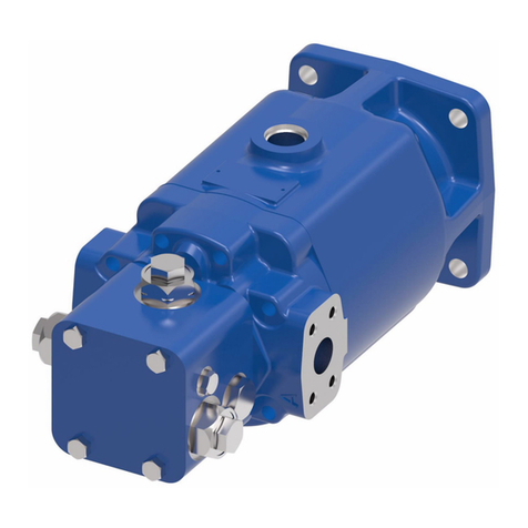
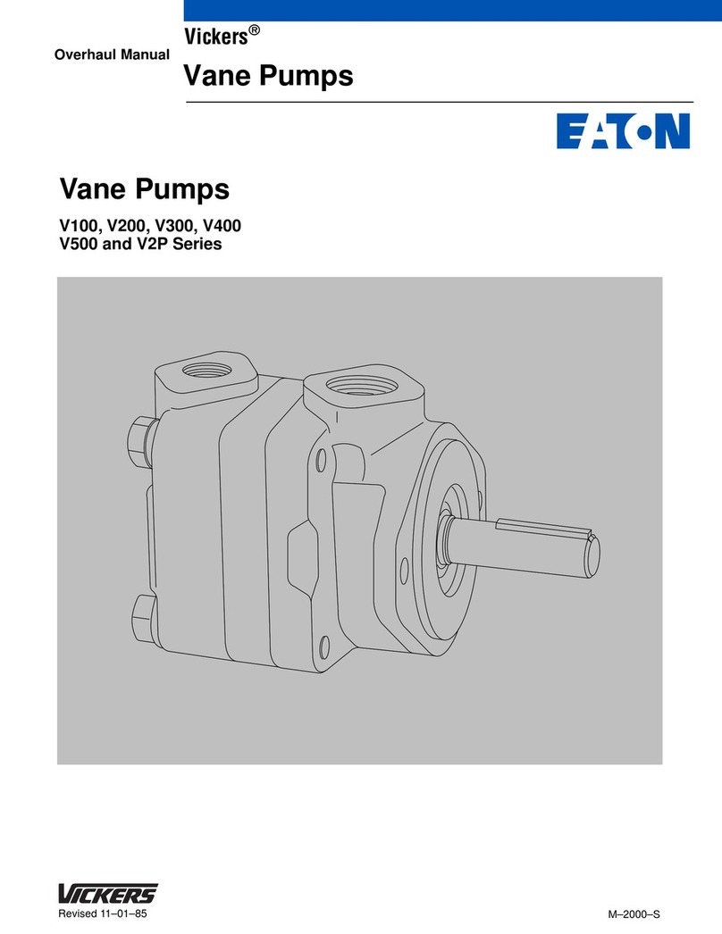
Eaton 70422 Owner's manual
Other Eaton Water Pump manuals
Eaton
Eaton Heavy Duty 2 Series User manual
Eaton
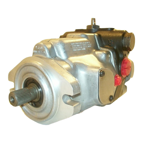
Eaton Vickers 25V Series Mounting instructions
Eaton
Eaton 70142 Owner's manual
Eaton
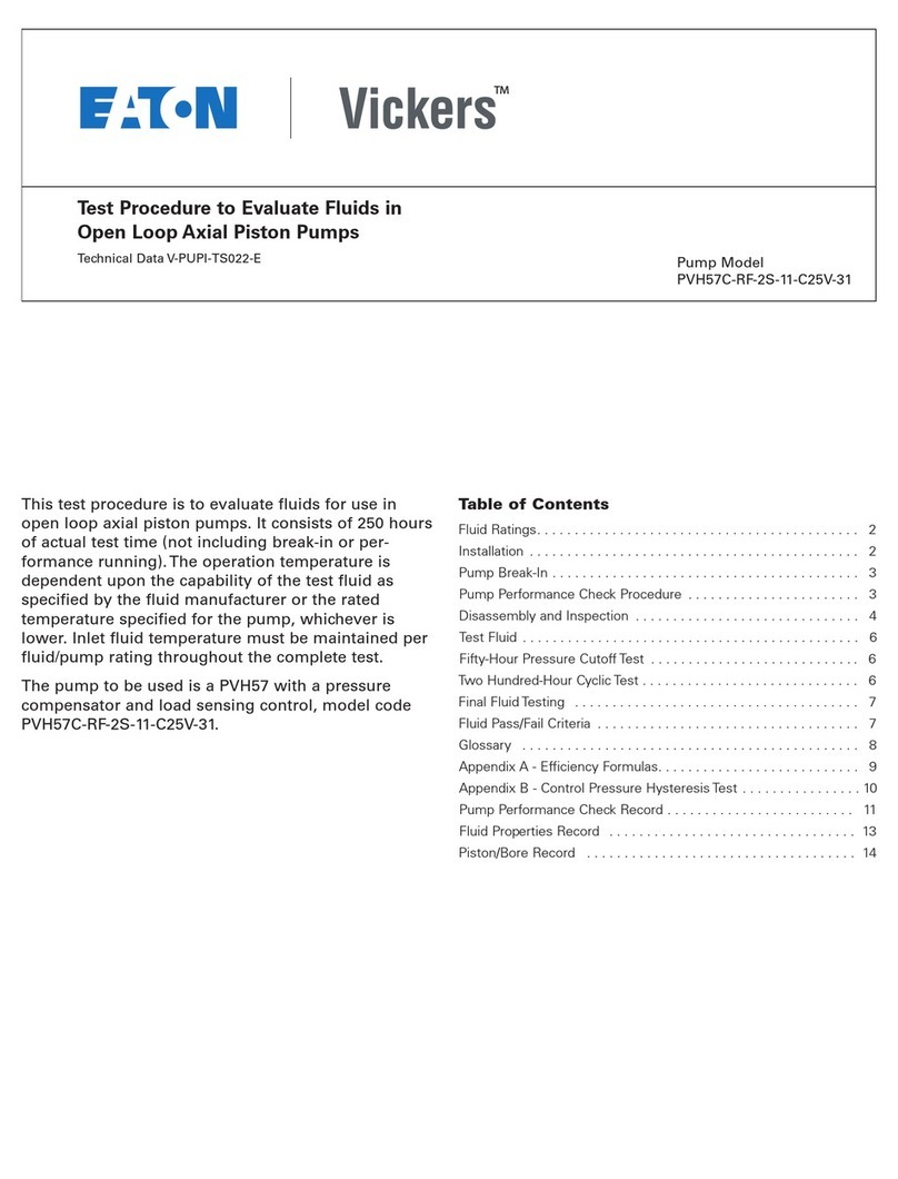
Eaton Vickers PVH57C-RF-2S-11-C25V-31 Instruction manual

Eaton
Eaton 70160 Owner's manual

Eaton
Eaton 620 User manual
Eaton
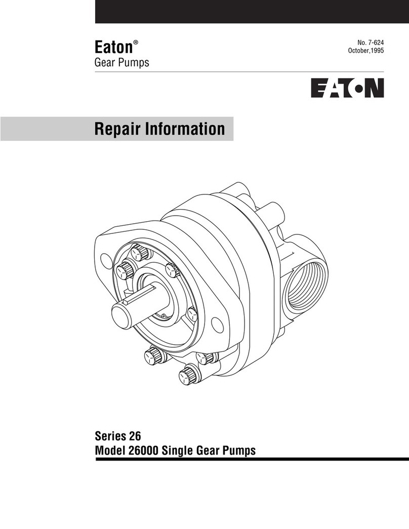
Eaton 26 Series Owner's manual
Eaton
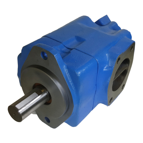
Eaton Vickers 2520V-20-282 Series User manual

Eaton
Eaton 220 User manual
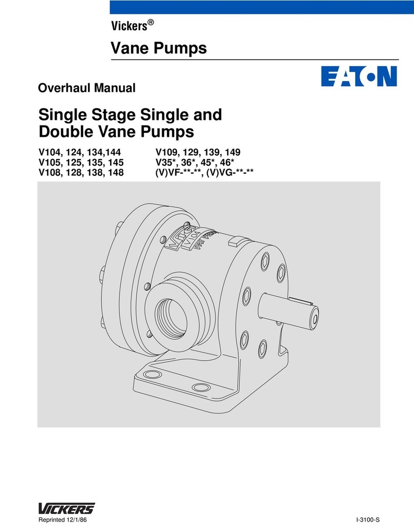
Eaton
Eaton Vickers VF Series User manual

Eaton
Eaton Vickers VMQ125S Series User manual
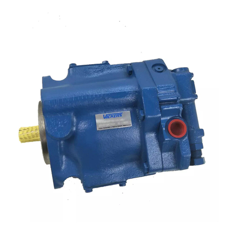
Eaton
Eaton Vickers PVE12 User manual
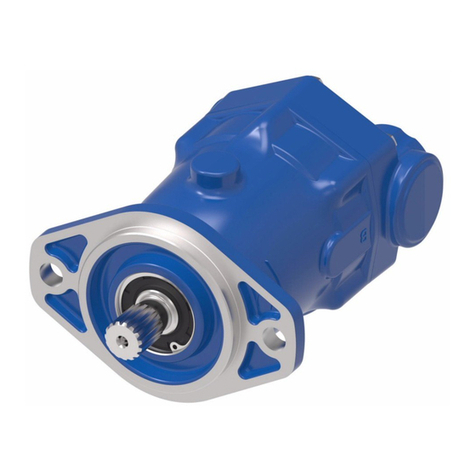
Eaton
Eaton 74318 Owner's manual
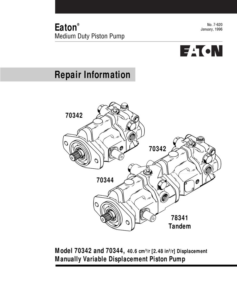
Eaton
Eaton 704342 Owner's manual

Eaton
Eaton 26 Series Owner's manual

Eaton
Eaton 70160 User manual
Eaton
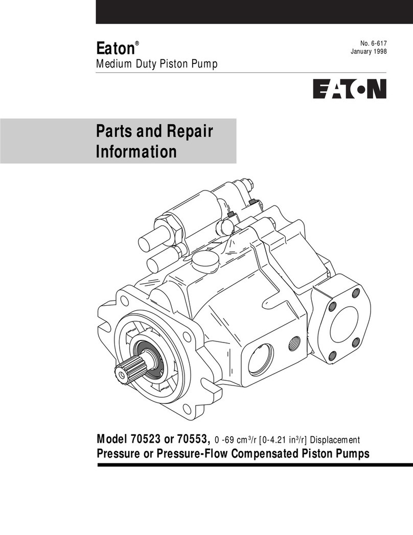
Eaton 70523 Owner's manual

Eaton
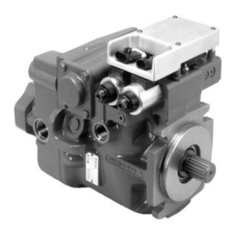
Eaton Hydrokraft PVW 250 User manual
Eaton
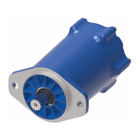
Eaton 2 Series Owner's manual
Eaton
Eaton 74624 Series Owner's manual
Popular Water Pump manuals by other brands

Watershed Innovations
Watershed Innovations HYDRAPUMP SMART FLEX Instructional manual

Graco
Graco Modu-Flo AL-5M instructions

Messner
Messner MultiSystem MPF 3000 operating instructions

Xylem
Xylem Bell & Gossett WEHT0311M Installation, operation and maintenance instructions

WilTec
WilTec 50739 Operation manual

Franklin Electric
Franklin Electric Little Giant 555702 HRK-360S instruction sheet

Ingersoll-Rand
Ingersoll-Rand PD02P Series Operator's manual

VS
VS ZJ Series Operating instruction

Flotec
Flotec FPZS50RP owner's manual

SKF
SKF Lincoln FlowMaster II User and maintenance instructions

Xylem
Xylem Lowara LSB Series Installation, operation and maintenance instructions

Water
Water Duro Pumps DCJ500 Operating & installation instructions

Action
Action P490 Operating instructions & parts manual

Flo King
Flo King Permacore Reusable Carbon Bag Disassembly. & Cleaning Instructions

ARO
ARO ARO PD15P-X Operator's manual

Pumptec
Pumptec 112V Series Operating instructions and parts manual

Virax
Virax 262070 user manual

Neptun
Neptun NPHW 5500 operating instructions

