Acoustical Performance Partnership Eastern Acoustic Works Group E Summary Specifications
One
Main
Street,
Whitinsville,
MA
01588
•
(508)
234
-
6158
•
FAX
(508)
234
-
8251
•
Email
[email protected] •
Web
http://www.eaw.com
A
C
O
U
S
T
I
C
A
L
P
E
R
F
O
R
M
A
N
C
E
P
A
R
T
N
E
R
S
H
I
P
One
Main
Street,
Whitinsville,
MA
01588
•
(508)
234
-
6158
•
FAX
(508)
234
-
8251
•
Email
[email protected] •
Web
http://www.eaw.com
EAW products are continually improved. All specifications are therefore subject to change without notice. • PUB# MXSeries/4p/5/21/97 • Printed In USA
Group E Performance Specifications
Close Coupled Processors
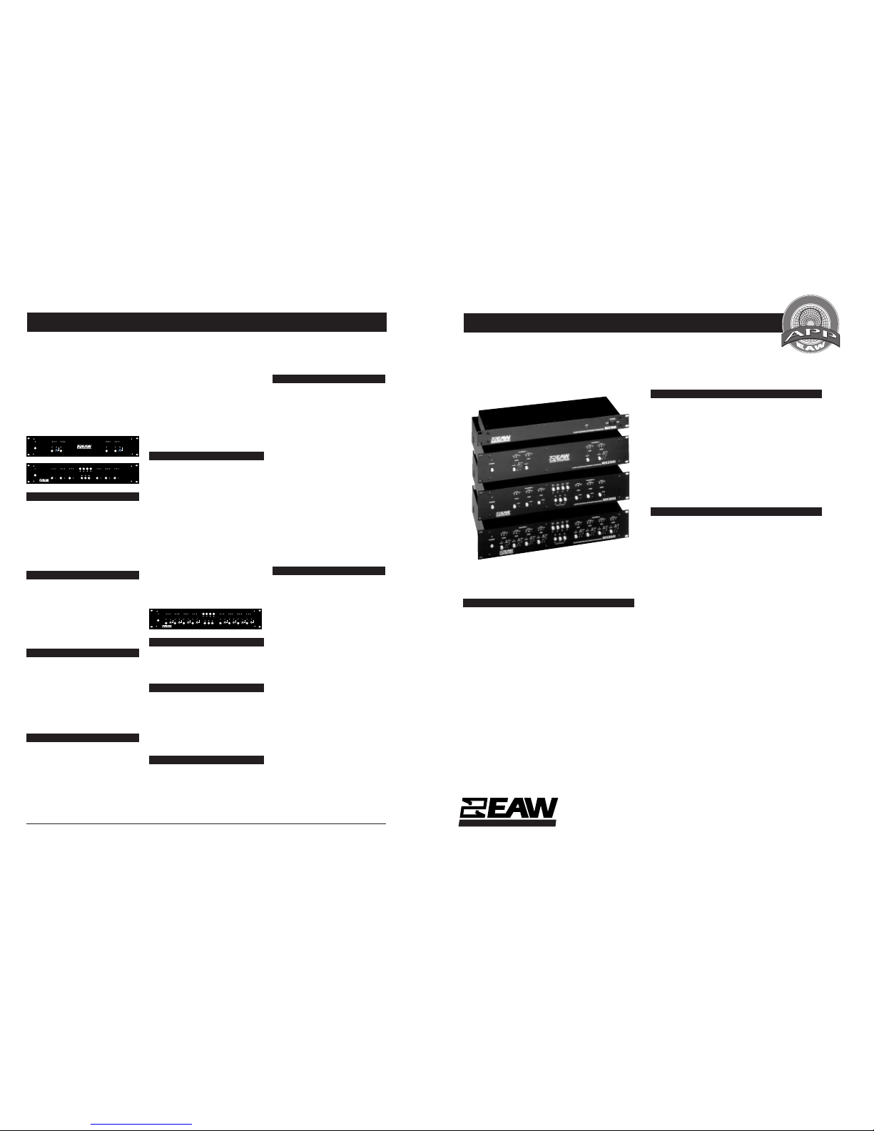
Specifications for Close Coupled Electronic Processors: MX100, MX200i, MX300i, MX800i
EASTERN ACOUSTIC WORKS
CONFIGURATIONS
Each MX Series processor is configured (Close Coupled) to a particular
EAW loudspeaker system or combination of systems. When ordering
MX Series processors, it is recommended that you contact an autho-
rized EAW sales agent, or the factory itself, to be sure that you order
the correctly configured processor for your sound system or project.
MX200i, MX300i and MX800i processors can be reconfigured in the
field, but this procedure is best performed by an authorized EAW
service center or EAW factory service.
SERVICE DEPARTMENT
For warranty repairs, replacement parts or other service needs, contact the
EAW Service department at 800/992-5013 or 508/234-6158 during
normal business hours. The Service fax number is 508/234-3776.
DESCRIPTIONS
MX100
The MX100 CCEP™ is a two-channel, two-way electronic subwoofer
crossover. The low frequency output is configurable either as a summed
monaural or stereo output. Special configurations are also available to
biamp two-way fullrange speaker systems.
MX200i
The MX200i CCEP™ is a two-channel, two-way electronic crossover,
supplied configured for use with specific EAW loudspeaker systems or
combinations of systems. Each frequency band output features overload
protection circuitry.
MX300i
The MX300i CCEP™ is a two-channel, three-way electronic crossover,
supplied configured for use with specific EAW loudspeaker systems or
combinations of systems. Each frequency band output features overload
protection circuitry.
MX800i
The MX800i CCEP™ two-channel, four-way electronic crossover sup-
plied configured for use with specific EAW loudspeaker systems or
combinations of systems. Each frequency band output features overload
protection circuitry.
CLOSE COUPLED PROCESSING
The concept of Close Coupled electronic processing (CCEP™) is central
to the EAW design process. EAW engineers integrate electronic signal
processing into the total loudspeaker system, but we recognize that
electronics can only improve performance after all other electro-
mechanical factors have been optimized. MX Series processors incorpo-
rate functions such as complex asymmetrical crossover filters, phase
compensation, low frequency excursion control, amplifier clipping
protection limiting and high frequency horn equalization. All of these
parameters are configured for a particular loudspeaker system in an
iterative design process using EAW’s rapid data acquisition facility and
in-house multi-platform computer network.
when the two signals being summed are in
phase with each other. The amplitude responses
of the filter and loudspeaker may each be
correct. But when they are combined, phase
errors can easily be introduced, so that the
overall response is not flat. Definition and intel-
ligibility are lost. Attempts to correct crossover-
related phase errors through equalization may
disguise the problem, but cannot cure it. The
result may produce acceptable measurements
with low resolution test equipment such as 1/
3 octave analyzers. More detailed measure-
ments as well as simple listening tests confirm
that attempts to compensate for phase errors
with equalization produce an inconsistent sys-
tem with audible irregularities.
ASYMMETRICAL FILTERS
The MX200i and MX300i CCEPs use multiple
second order filters to create the fourth order
filters on each frequency band. These second
order filters are independently adjustable. These
adjustments, performed with the aid of inte-
grated test data acquisition and computer
modelling software, are a key element in the
close coupling of the crossover to a particular
speaker system.
MX800i
The MX800i CCEP two-channel, four-way
electronic crossover is designed for fixed instal-
lations and touring sound systems. It is supplied
configured for use with specific EAW systems.
This ensures optimum system performance un-
der all conditions, without the burden of “set-
ting up.” The unit is compact, robust and very
reliable, yet simple to service should the need
arise.
CLOSECOUPLED ELECTRONIC PROCESSOR
MX800i
SUBWOOFERMODE
OFF DIST
SUB
MONO
SUB
+6dB
HFEQ
OUT
SIGNAL
-40dB -6dB LIMIT
SIGNAL
-40dB -6dB LIMIT
SIGNAL
-40dB -6dB LIMIT
CHANNEL2
SUB LOW MID
ADJ
SUBØ
180°
SIGNAL
-40dB -6dB LIMIT
SIGNAL
-40dB -6dB LIMIT
SIGNAL
-40dB-6dB LIMIT
CHANNEL1
MID
POWER
LOW SUB
MUTE
SIGNAL
-40dB -6dB LIMIT
HIGH
MUTE MUTE MUTE
EASTERNACOUSTIC WORKS
SIGNAL
-40dB -6dB LIMIT
HIGH
MUTE MUTE MUTE MUTE
UNCAL UNCAL UNCAL UNCAL UNCAL UNCAL UNCAL UNCAL
-6 0 -6 0-6 0-6 0-6 0 -6 0 -6 0 -6 0
OVERLOAD PROTECTION
Each frequency band has an independent true-
RMS above threshold infinite compressor to
reduce gain momentarily whenever the preset
output limit is approached.
LOW FREQUENCY CONTROL
The MX800i’s lowest operating output band
incorporates a low frequency control circuit
that provides stepdown alignment equaliza-
tion along with high pass filtering to prevent
operation below system cutoff. This equalized
filter is controlled to provide maximally extended
distortion-free low frequency response at all
power levels.
SUB-BASS MODE
Front panel switches select “OFF”, “ADJacent”
and DIStant” sub-bass modes. This maintains
the correct sound balance and source localiza-
tion regardless of whether or not you use
subwoofers, or whether the subwoofer sys-
tems are mounted adjacent to the main speaker
MX200i, MX300i, MX800i
MX200i, MX300i
TheMX200i CCEPis a two-channel,two-way and
the MX300i CCEP™ is a two-channel, three-way
electronic crossover. Both are designed for use in
fixed installations and touring sound systems and
aresupplied configuredfor use withspecific EAW
loudspeaker systems or combinations of
subwoofers and full range systems. This removes
the burden of “setting up” from the end user and
assures optimum system performance under all
conditions. CCEPs are compact, robust and very
reliable, yet simple to service should the
need arise.
HIGH
CLOSECOUPLED ELECTRONIC PROCESSOR
MX200i
SIGNAL
-40dB -6dB LIMIT
SIGNAL
-40dB -6dB LIMIT
CHANNEL2
LOW
SIGNAL
-40dB -6dB LIMIT
SIGNAL
-40dB -6dB LIMIT
CHANNEL1
POWER
LOW
MUTE MUTE
EASTERNACOUSTIC WORKS
HIGH
MUTE MUTE
UNCAL UNCAL
-10 0 -10 0
CLOSECOUPLED ELECTRONIC PROCESSOR
MX300i
SUBWOOFERMODE
ADJ OFF DIST
SUBØ
180°SUB
MONO
SUB
+6dB
HFEQ
OUT
SIGNAL
-40dB -6dB LIMIT
SIGNAL
-40dB -6dB LIMIT
SIGNAL
-40dB-6dB LIMIT
SIGNAL
-40dB -6dB LIMIT
SIGNAL
-40dB -6dB LIMIT
SIGNAL
-40dB -6dB LIMIT
CHANNEL2CHANNEL1
HIGHPOWER LOW SUB SUB LOW HIGH
MUTE MUTE MUTE MUTE MUTE MUTE
EASTERNACOUSTIC WORKS
OVERLOAD PROTECTION
Each frequency band has its own overload
protection circuitry. A true-RMS above thresh-
old infinite compressor momentarily reduces
gain whenever the preset output limit is ap-
proached. This is normally set to prevent the
power amplifiers from being driven into clip-
ping, but may also be intentionally set lower to
protect particularly delicate drivers or to limit
the maximum long term output of the system.
LOW FREQUENCY CONTROL
The MX300i’s low frequency output incorpo-
rates a low frequency control circuit to provide
both stepdown alignment equalization and
high pass filtering to prevent operation below
system cutoff. This equalized filter is controlled
to provide maximally extended distortion free
low frequency response at all power levels.
The threshold for this circuit is pre-set at the
factory.
SUB-BASS MODE
The MX300i’s front panel switchable sub-bass
modes - “OFF”, “ADJacent” and “DIStant” -
enable the user to maintain the correct sound
balance and source localization with and with-
out subwoofers and whether the subwoofers,
if used, are adjacent to the main speaker stacks
or located remotely. This is particularly valu-
able when sub-bass systems are mounted at
ground level and the rest of the system is
flown.
PHASE COMPENSATION
Each MX200i or MX300i configuration incor-
porates phase correction circuitry, tailored to
the specific systems for which it is designed.
This technique compensates for the phase
response of the drivers and their relative place-
ment in the enclosure to present the listener
with accurate, phase coherent sound. At the
crossover points of any multi-way system, the
sum of the upper and lower output bands
should be flat: This state of affairs occurs only
stacks or located remotely. This function is
particularly useful when subwoofers are
mounted at ground level and the rest of the
system is “flown.”
PHASE COMPENSATION
At the crossover points of any multi-way sys-
tem, the sum of the upper and lower output
bands should be flat so as not to cause any
peaks or dips in the overall system response.
However, this state of affairs occurs only when
the two signals being summed are in phase
with each other.
The amplitude responses of the filter and loud-
speaker may each be correct. But when they
are combined, phase errors are almost certain
to occur so that the overall response is not flat.
Many manufacturers use equalization in an
attempt to combat this shortcoming but
equalization is only an attempt to hide the
problem; it doesn’t cure it.
The MX800i CCEP™ incorporates phase cor-
rection circuitry, tailored to the specific system
for which it is configured. This circuit compen-
sates for the phase response of the drivers and
their relative placement in the enclosure to
present the listener with accurate, phase co-
herent sound. Without phase correction, the
high frequency drivers in a multi-way system
tend to lag behind low frequency drivers,
causing a significant loss of definition and
intelligibility.
ASYMMETRICAL FILTERS
The MX800i CCEP™ incorporates independent
internal settings for each of the six filters on
each channel. Using each filter’s individual
settings, we are able to independently adjust
both pairs of second order filters used to create
the ultimate fourth order slope. This asym-
metrical filter design is a key element in the
close coupling of the crossover to a particular
speaker system to compensate for the acousti-
cal characteristics. of individual elements.
• Front Panel Output Adjustments - up to 6 dB
level reduction on each band, with auto-
matic tracking of protection thresholds.
• QuickConfiguration Programming- allclosely
coupled system-specific functions are located
on an internal plug-in PC board for easy re-
configuration.
• Improved Output Line Drive Capability - 10Ω
output impendance: no need to adjust out-
put balances.
• Meets UL, CSA & European Safety Standards.
• Full Transient Protection - for safe, quiet turn-
ons and -offs.
• Enhanced Subwoofer Operating Modes -
allows true three-way operation with or with-
out subwoofers.
• Front Panel Indicators - watch band has LED
indicators for signal presence, maximum safe
output level and output level calibration.
• Rugged Mechanical Construction - built in
the USA with heavy gauge materials for true
reliability on the road.