EB TECHNOLOGY Nologo START-S102 Product manual

START-S102
START-S102_140218_VXX03 _GB www.ebtechnology.it www.nologo.info
• Control unit for lights or motor
• Supplied with 433Mhz plug-in receiver
Instructions and warnings for the installer
100%
ITALY
Connection for the Motor
Connection for light groups
LED 1
LED 2
Led 1 Red lit on
control unit with
MOTOR function
Led 1 Green lit on
control unit with
LIGHT function
*
*
*First second after turning on of the control unit START-S102 is possible to choose with button Pthe
required function. Each pression of the button changes into: Command MOTOR Led 1 RED, Command
LIGHTS Led 2 GREEN.
N.A.
Connection commandes P1 / P2
N.A.
FUNCTION:
Command MOTOR:
P1 Input -> Command OPEN
P2 Input -> Command CLOSE
Command LIGHT:
P1 Input -> Command LIGHT 1
P2 Input -> Command LIGHT 2
The connection of the commands P1 / P2 can be done with every button or N.O. contact. When more devices
are available, connect them in parallel.
-7-
-6-
-5-
-4-
-3-
-2-
-1-
P1 Input
P2 Input
Open
Close
Phase 230 Vac
Neutral 230 Vac
M
CL
OP
COM
-7-
-6-
-5-
-4-
-3-
-2-
-1-
P1 Input
P2 Input
Light 2
Phase 230 Vac
Neutral 230 Vac
Light 1
Light 2
Light 1
-7-
-6-
-5-
-4-
-3-
-2-
-1-
P1 Input
P2 Input
Light 2
L 230 Vac
N 230 Vac
Light 1

START-S102 Operating guide
-2-
Using the unit improperly and performing repairs or
modifi cations personally will void the warranty. The
producer declines any responsibility for damages
due to inappropriate use of the product and due to
any use other than the use the product was desig-
ned for. The producer declines any responsibility for
consequential damages except civil liability for the
products.
Safety precautions
Introduction
Index Chapter
Par. Description Pag.
1 Installation of the control unit 3
1.1 Diagram of the control unit
and electrical connections
2 Learning of the remote controls 4
2.1 COMPLETE RESET of the memory
2.2 Activation / Deactivation of the Rolling HCS
2.3 Memorization of the remote control:
Command OPEN / LIGHT 1
5
2.4 Memorization of the remote control:
Command CLOSE / LIGHT 2
2.5 Cancellation of one single remote control
3 Function 6
3.1 Command of the MOTORS
3.2 Command of the LIGHTS
3.3 Function as two channels RECEIVER
3.4 Programm of the OUTPUTS
4 Reset to the factory settings
Consumption MAX
Contact Relay
3 A
Technical description
Foreword
This manual provides all the specifi c information you
need to familiarize yourself with and correctly operate
your unit. Read it very carefully when you purchase the
instrument and consult it whenever you have doubts
regarding use and before performing any maintenance
operations. Nologo has the right to modify the product
without previous notice.
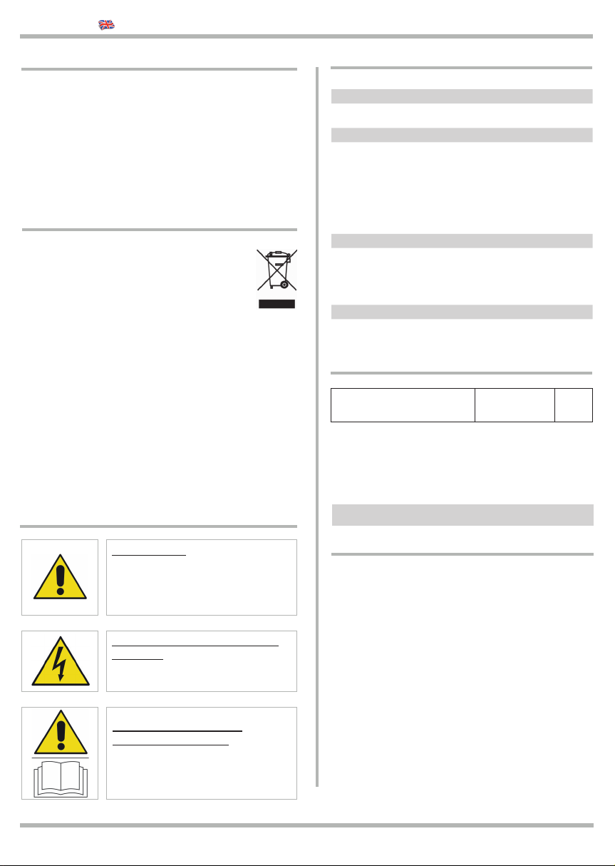
Environmental protection
measures
Information regarding the environment for
customers within the European Union. Eu-
ropean Directive EC 2002/96 requires that
units bearing this symbol on the unit and/or
on the packaging be disposed of separately
from undiff erentiated urban wastes.
The symbol indicates that the product must not be dis-
posed of with the normal household wastes. The owner
is responsible for disposing of this product and other
electrical and electronic equipment through specifi c
waste collection facilities indicated by the government
or local public agencies. Correct disposal and recycling
help prevent any potentially negative impact on the en-
vironment and human health. To receive more detailed
information regarding disposal of your unit, we recom-
mend that you contact the competent public agencies,
the waste collection.
Symbols and warning
DANGEROUS
This is a warning and if it is not re-
spec it can provoque material dam-
age.
DEVICE UNDER ELECTRICITY
TENSION
The installation should be done
only from professional installer.
READ CAREFULLY THE
OPERATING MANUAL
Read carefully this manul before in-
stallation and keep it for the future.

-3-
1.1 Diagram of the control unit and electrical connections
1 Installation of the control unit
Connection of the POWER
NETWORK
The phase of the power supply
must be protected from an magne-
tic-thermal switch or from two 5 A
fuses.
A diff erential switch is recommen-
ded but not necessary if it is alrea-
dy available in the installation.
Connection of the MOTOR
Pay attention not to renverse the
poles OPEN AND CLOSE.
In case of doubts, put manually the door in the
middle. Be ready to stop the door with a STOP
command!
START-S102 Operating guide
Command 1 7 Input command 1 (NO)
Command 2 6 Input command 2 (NO)
MOT Open / Light 1 5 Output for connection motor OPEN or LIGHTS 1
MOT Close / Light 2 4 Outpur for connection of the MOTOR CLOSE or LIGHTS 2
3
230 Vac (L) 2 230 Vac Power Supply 50 Hz, Phase
230 Vac (N) 1 230 Vac Power supply 50 Hz, Neutral
Button P
1 2 3 4 5 6 7
Antenna
L2
green
L1
red
Link, cut or leave
according to the mode
-7-
-6-
-5-
-4-
-3-
-2-
-1-
-7-
-6-
-5-
-4-
-3-
-2-
-1-
1 2 230Vac Power Supply
3 5 Connection of the motor or lights
6 7 Input for external commands
Button P
Managing of the radio receiver, reset
of the control unit, programm of the
diff erent functions

-4-
START-S102 Operating guide
2 Learning of the remote controls
MEMORY CAPACITY
The receiver can manage up to 190 remote controls with standard codes: 1 button each remote control.
TYPE OF THE CODE
This receiver can manage standard codes from 12 up to 64 bit and rolling tipo HCS©. The fi rst transmitter establish
the code’s type and next remote controls must have the same code. Concerning the rolling code it is possible to
activate or deactivate the key and the rolling code counter. If you choose this function you can select the security
level of the receiver.
1Make sure the outputs are not activated and the receiver is not learning Led 1 Red and
Led 2 Green switch OFF
2 >Keep pressed the button Puntil the red led is switching ON (almost 10 seconds)
3Release the button and wait several fl ashes and wait until the LED L1 RED switches off
2.1 CANCELLATION of the memory
10 seconds
P L1
P L1
This operation can cancell all codes and you reset the receiver at the
factory settings. It is necessary to reset the memory in order to learn the
fi rst Remote control to avoid old codes and not used in the installation:
L1 L2
!RESET the memory
at fi rst installation
2.2 Activation / Deactivate of the Rolling HCS
This process needs to activate or deactivate the rolling code counter. If this control will be activated, the receiver will
accept only rolling code with the same manufacturer’s protocol and it will checked that the remote control cannot
be cloned.
1Make sure the receiver output is not activated
2 > > Press twice button Pand release,
Wait four fl ashes. Led 1 Red is lit on
3> Press again and release the button. The red led turns off if the function is not
activated while it fl ashes if the function is activated.
P P L1
P
L1
TURN OFF:
Not activated
TURN ON:
Activated

-5-
START-S102 Operating guide
2.4 Learning of the remote control: Command CLOSE / LIGHT 2
1Make sure the receiver output is not activated.
2 > > Press twice button Pand release,
Wait four fl ashes. The red LED 1 is lit on
3
Press the button of the remote control in 10 seconds . If the code has been
learnt the red led fl ashes fast, if the red led fl ashes slowly it means the
memory is full, if the red led doesn’t fl ash it means that the remote controls is
not compatible. If you want to learn other remote controls in the outpu 1 repeat
the operation from point no.1
P P L1
2.3 Learning of the remote control: Command OPEN / LIGHT 1
1Make sure the receiver output is not activated
2 >Press and release button P. Led 1 Red is lit on.
3
Press the remote control in 10 seconds. If the code has been learnt the red led fl ashes
fast, if the red led fl ashes slowly it means the memory is full, if the red led doesn’t fl ash
it means that the remote controls is not compatible. If you want to learn other remote
controls in the output 1 repeat the operation from point no.1
P L1
2.5 Cancellation of one single remote control
1It is possible to cancel one single remote control:
2>Press and release button P. Led 1 Red is lit on
3
Press the remote control. If this code has been learnt, the red led fl ashes for 4 seconds (9
fl ashes) and go back to normal conditions. During this time press the button of the remote
again and the code will be cancelled.
P L1

-6-
3.1 Command of the MOTOR
START-S102 Operating guide
3 Functions
Connection of the MOTOR
The control unit is programmed for 60 seconds of working time. This function is useful in case you need to perso-
nalize the working time. Follow these steps.
3.2 Programm of the WORKING TIME
!The control unit START-S102
doesn’t reclose automatically
!The control unit is designed for
motors with mechanical limit
switches.
1Make sure the receiver outputs are not activated
2 Press the remote control for OPEN command or button P1
3>Keep pressed for 5 seconds button Puntil the red led L1 is lit on.
Now it starts the time
4After counting the opening time, LED L1 and 2 fl ash
5> After this time press again button P,
The time has been learnt
6To memorize the CLOSING TIME press the remote control for CLOSING
or button P1 and start from point no.3 again
P L1
P L1
L2
L1
After the control unit will be switched on, you need to choose the functions in 5 seconds time with button P: Com-
mand MOTOR Led 1 Red, Command LIGHTS Led 2 Green. The standard function is the MOTOR Command.
-7-
-6-
-5-
-4-
-3-
-2-
-1-
P1 Input
P2 Input
Open
Close
Phase 230 Vac
Neutral 230 Vac
M
CL
OP
COM

-7-
START-S102 Operating guide
3.3 Command LIGHTS
3.5 Impostazione USCITE
You can select all functions with button P. When the output is activated, press button P, leds lit on, press Puntil
L1-L2 show the function which habe been activated.
Man’s deatch function: The outputs are not activated as soon as the button
will be released.
Led L1 RED:
FIX
Bistable: Each command the output renverse the condition Led L2 GREEN:
FIX
Timing with
Recharge time:
Once the output have been activated, the led will
switched off after the working time and after pres-
sion the time will be recharged.
Led L1 RED:
FLASHING
Bistable
with timing function:
Each command of the output renverse the condition
of the control unit, if activated it will lit on after that
time:
Led L2 GREEN:
FLASHING
This functions are useful either for LIGHT or for MOTOR command, and as two channels receiver.
To timed the outputs for LIGHT USE, read par. 3.2
LIGHTS 230 Vac LIGHTS 12/24 V
3.4 Use as a two channels receiver
3.5 Programm of the OUTPUTS
-7-
-6-
-5-
-4-
-3-
-2-
-1-
P1 Input
P2 Input
Light 2
L 230 Vac
N 230 Vac
Light 1
Light 2
Light 1 -7-
-6-
-5-
-4-
-3-
-2-
-1-
P1 Input
P2 Input
Light 2
L 230 Vac
N 230 Vac
Light 1 Light 2
Light 1
12/24 V
230 Vac Power Supply
OUT 1
N.O.
OUT 2
N.O.
-7-
-6-
-5-
-4-
-3-
-2-
-1-
P1 Input
P2 Input
Output 2
Com Outputs
L 230 Vac
N 230 Vac
Output 1 Cut the link for this
confi guration!
Cut the link for this
confi guration!

-8-
5 Declaration of conformity
(according to EC Directive 2006/42, Attachment II, part 1, ses. A)
The undersigned Ernestino Bandera,
Administrator
DECLARES THAT:
Dairago, 14/06/2017
The Administrator
Ernestino Bandera
Manufacturer: EB TECHNOLOGY SRL
Adress: Corso Sempione 172/5
21052 Busto Arsizio VA Italy
Name of the product: START-S102
Control unit for lights or motor
EB TECHNOLOGY S.r.l.
Corso Sempione 172/5,
21052 Busto Arsizio VA Italy
posta@ebtechnology.it
www.ebtechnology.it
NOLOGO S.r.l.
Via Antonio Pacinotti 44
20020 Villa Cortese MI Italy
tel. +39 0331.430457
fax.+39 0331.432496
www.nologo.info
2002/95/EC
START-S102 Operating guide
We introduced this funciton to reset at factory settings which:
- Function MOTOR
- Program of the outputs: BISTABLE with TIMING
- Deactivation time: 60 seconds
1Switch off the control unit
2Power the control unit, the led lits on for 5 seconds
3> In this time press the button Puntil the red led 1 is fl ashing,
this confi rm the reset of the control unit.
P L1
4 Reset at factory settings
THE PRODUCT COMPLIES
with what is outlined in the European Community directive:
2006/42/CE
EC DIRECTIVE 2006/42 ISSUED BY THE EUROPEAN PARLIAMENT
AND COUNCIL on may 17, 2006 harmonizing the legislation of the member
countries regarding machinery.
Ref: Attached II, part B (CE conformity declaration of the manufacturer)
THE PRODUCT IS CONFIRMED TO THE EUROPEAN NORMES,
changed from the EU Directive 2006/42/CE Council of 14th Oct 2004
2014/35/EU
DIRECTIVE 2014/35/EU OF THE EUROPEAN PARLIAMENT AND OF THE
COUNCIL of 26 February 2014 on the harmonisation of the laws of the Member
States relating to the making available on the market of electrical equipment
designed for use within certain voltage limits.
Referred to the harmonized rules: EN 60335-1
2014/30/EU
DIRECTIVE 2014/30/EU OF THE EUROPEAN PARLIAMENT AND OF THE
COUNCIL of 26 February 2014 on the harmonisation of the laws of the Member
States relating to electromagnetic compatibility.
Referred to the harmonized rules: EN 61000-6-2 EN 61000-6-3
THE PRODUCT IS CONFORMED
to the essentials requirements art. no.3 of the European Directive for
them the product is used.
2014/53/CE
DIRECTIVE 2014/53/EU OF THE EUROPEAN PARLIAMENT AND OF THE
COUNCIL of 16 April 2014 on the harmonisation of the laws of the Member
States relating to the making available on the market of radio equipment.
Referred to the norms:
ETSI EN 300 220-3 ETSI EN 301 489-1 ETSI EN 301 489-3
As indicated in the European Directive 2006/42/CE we recommend that is
not allowed the get in service the product as long as the machine, where
the product is integrated, hasn’t be identifi ed and declared confi rmed to
the european Directive 2006/42/EC.
Table of contents
Other EB TECHNOLOGY Control Unit manuals
Popular Control Unit manuals by other brands

Siemens
Siemens Flowrite 599 Series Technical instructions

ensto
ensto ECO900 operation instruction

EWM
EWM Tetrix AC/DC Comfort 2.0 operating instructions

syscomtec
syscomtec SCT-IPKVM-CX user manual

extronics
extronics ISOLATE 100: ISOLATE 100M operating manual

Allen-Bradley
Allen-Bradley Series B user manual

Afag
Afag GMQ 32/RM 16 Assembly and operating instructions

ABB
ABB ACS880-04 drive modules Hardware manual

Solinst
Solinst 464 Mk3 250 psi Replacement

Apacer Technology
Apacer Technology EFC-D Series user manual

Telit Wireless Solutions
Telit Wireless Solutions UE910 series Hardware user's guide

PT Coupling
PT Coupling Maxi-Dry Disassembly instructions