Webasto Introduction | 1
9039398A_WSM_eThermo_Top_Eco_EN 3 / 19
1 Introduction
1.1 About this document
This workshop manual is designed to assist trained personnel in
resolving application queries and other issues relating to the
eThermo Top Eco 20 P | 30 P.
NOTE
Do not open the heater.
If faulty always replace the complete heater.
1.2 Purpose of the document
This workshop manual is part of the product and contains all
the information required to resolve malfunctions of the eTh-
ermo Top Eco 20 P | 30 P.
1.3 Using this document
nRead and observe this workshop manual when determining
and carrying out repairs to the application or the replace-
ment of the eThermo Top Eco 20 P | 30 P.
nThe Installation Instructions and the Operating Instructions
and the important information and legal provisions con-
tained therein should always be read and observed.
1.4 Use of symbols and highlighting
DANGER
This signal word denotes a hazard with a high degree
of risk which, if not avoided, will lead to death or seri-
ous injury.
WARNING
This signal word denotes a hazard with a moderate de-
gree of risk which, if not avoided, may lead to minor or
moderate injury.
CAUTION
This signal word denotes a hazard with a low degree of
risk which, if not avoided, will lead to minor or moder-
ate injury.
NOTE
This signal word denotes a Special Technical Feature or
(if not observed) potential damage to the product.
Refers to separate documents which are enclosed or
can be requested from Webasto.
Symbol Explanation
Requirements for the following necessary ac-
tion
Necessary action
1.5 Warranty and liability
Webasto shall not assume liability for defects or damage that
are the result of the installation and operating instructions being
disregarded. This liability exclusion particularly applies for:
nmechanical damage to the equipment
ninstallation by untrained personnel
nconversion of the unit without permission from Webasto
nimproper use
nUse of non-genuine replacement units
nRepairs or device replacement not carried out by a Webasto
service workshop
nUse of unsuitable accessories
nInsufficient coolant supply before, during and after heating
mode
1.6 Qualifications of installation
personnel
The installation personnel must have the following qualifica-
tions:
nSuccessful completion of Webasto training.
nCorresponding qualification for working on technical sys-
tems.
nInstallation and operating instructions as well as the notes
it contains must be observed.
DANGER
Any work on the eThermo Top Eco 20 P | 30 P must
only be carried out by electricians qualified to carry out
electrotechnical work on high-voltage systems in
vehicles.
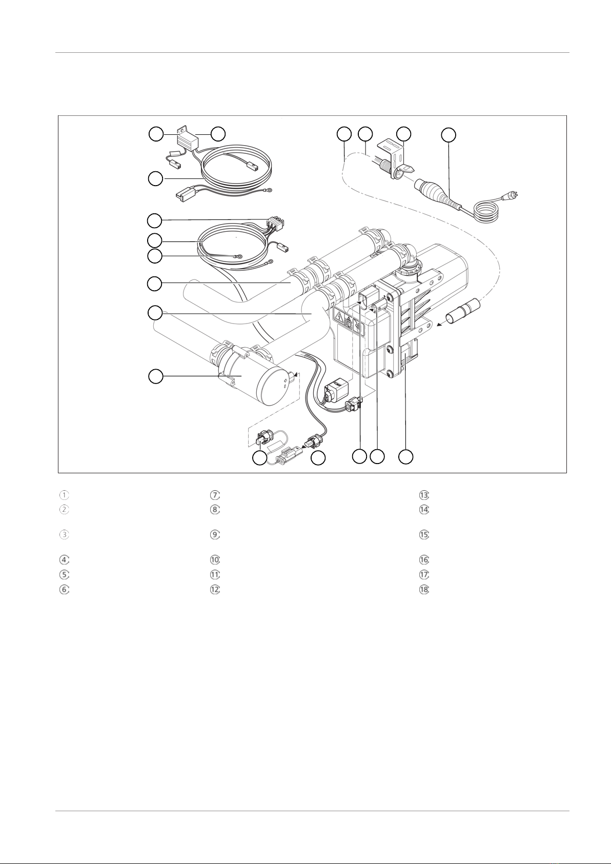
1.7 Spare parts
There are no spare parts for the eThermo Top Eco 20 P | 30 P
heater; the unit can only be replaced. The components, such as
the coolant pump, are available as single parts.
You can find original spare parts:
nIn the Webasto spare parts catalogue
nIn the dealer portal http://dealers.webasto.com
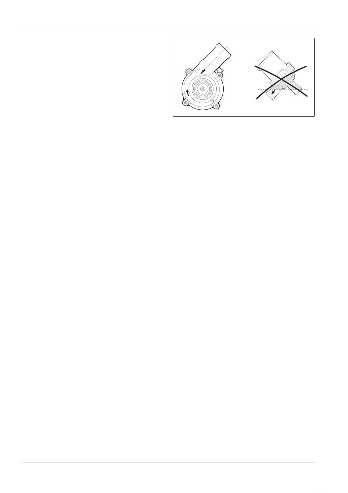
1.8 Safety precautions
DANGER
To avoid electric shocks, guard against electric shocks,
risk of fire and risk of damage caused by hot, moving or
sharp objects.
uDo not adapt the heater supply cables or shorten
or lengthen them yourself.
DANGER
Before working on the heater: disconnect the power
supply to the heater, the coolant pump and the vehicle
fan.
uDisconnect the negative terminal of the vehicle bat-
tery
uRemove the power cable
DANGER
To guard against electric shocks, the heater may only
be connected when the 230V socket outlet with earth-
ing contact is protected with an RCD switch (circuit
breaker) with a rated residual current of max. 30mA. If
you have any questions, please contact an authorized
electrician.
The heater may only be connected to power grids that
are protected with a minimum current and designed ac-
cordingly (10A for eThermo Top Eco 20P, 16A for
eThermo Top Eco 30 P).
The device should be properly connected to a
230V/50Hz socket outlet with earthing contact. This
should also be checked against the data on the type la-
bel.