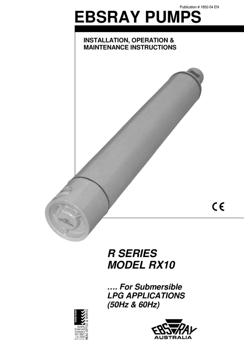
Ebsray R SERIES Guide

Publication # 1067-06
EBSRAY PUMPS
INSTALLATION, OPERATION &
MAINTENANCE INSTRUCTIONS
R SERIES
MODEL RB10 (50Hz and 60Hz)
…. For LPG APPLICATIONS
Pumping from underground tanks

CONTENTS
SECTION 1 – GENERAL.............................................................................................................................................. 4
1.1 INTRODUCTION................................................................................................................................... 4
1.2 TRANSPORTATION, PACKING & STORAGE ..................................................................................... 4
1.3 RECEIVING INSPECTION.................................................................................................................... 4
1.4 HANDLING............................................................................................................................................ 4
1.5 WARRANTY.......................................................................................................................................... 4
SECTION 2 – SYSTEM DESCRIPTION....................................................................................................................... 5
2.1 EBSRAY RB10 LPG PUMPING SYSTEM ............................................................................................ 5
2.2 BYPASS VALVE – EBSRAY #RV18-VRS19......................................................................................... 5
2.3 NON-RETURN VALVE.......................................................................................................................... 5
SECTION 3 – INSTALLATION..................................................................................................................................... 6
3.1 LOCATION............................................................................................................................................ 6
3.2 COUPLING ALIGNMENT...................................................................................................................... 6
3.3 FOUNDATIONS.................................................................................................................................... 6
3.4 PUMP PIPING CONNECTIONS ........................................................................................................... 6
3.5 SYSTEM PIPING CONNECTIONS....................................................................................................... 6
3.5.1 Foot Valve (Non-Return Valve) ..................................................................................................... 7
3.5.2 Pump Inlet Pipe............................................................................................................................. 7
3.5.3 Pump Discharge Pipe.................................................................................................................... 7
3.5.4 Bypass Valve................................................................................................................................. 7
SECTION 4 – OPERATION.......................................................................................................................................... 8
4.1 DESCRIPTION...................................................................................................................................... 8
4.2 LUBRICATION...................................................................................................................................... 8
4.3 PRE-STARTUP CHECKLIST................................................................................................................ 8
4.4 STARTUP PROCEDURE...................................................................................................................... 8
4.5 PERIODIC INSPECTION...................................................................................................................... 8
SECTION 5 – MAINTENANCE..................................................................................................................................... 9
5.1 PREPARATION FOR DISASSEMBLY.................................................................................................. 9
5.2 DISASSEMBLY..................................................................................................................................... 9
5.3 INSPECTION ........................................................................................................................................ 9
5.4 SPARE PARTS..................................................................................................................................... 9
5.5 REASSEMBLY - PRELIMINARY......................................................................................................... 10
5.6 REASSEMBLY.................................................................................................................................... 10
SECTION 6 – PARTS DESIGNATION ....................................................................................................................... 11
SECTION 7 – TROUBLESHOOTING......................................................................................................................... 12
APPENDIX A – TYPICAL INSTALLATION P&ID ...................................................................................................... 15
APPENDIX B – SYSTEM PRE-STARTUP COMMISSIONING CHECKLIST............................................................. 16
APPENDIX C – EBSRAY PUMP RUN LOG............................................................................................................... 17
APPENDIX D – DECLARATION OF CONFORMITY ................................................................................................. 18
EBS-RAY PUMPS Pty. Limited
628 Pittwater Road
Brookvale NSW 2100 Australia
Phone: (+612 9905 0234)
Fax: (+612 9938 3825)
www.ebsraypumps.com.au
or Contact Ebsray Representative:

IMPORTANT NOTES
1. This Publication is TYPICAL ONLY and only relates to the specifications of the minimum equipment required to
ensure the optimum performance, maximum life and trouble-free operation of the Ebsray RB10 Pumpset and the
Pumping System in general.
2. Products with the mandatory European CE mark affixed indicate conformity to the essential health and safety
requirements via their applicable EU Directives (e.g. ATEX 94/09/EC, Machinery 98/37/EC etc).
As certain specific products/equipment outlined in this Publication are CE marked (meaning the equipment has
been assessed and supplied in conformity to those Directives), STRICT ADHERENCE with ALL the
instructions and recommendations forms an essential part in maintaining the product/equipment’s conformity.
Failure to comply with the instructions and recommendations contained in this Publication may void
CE conformity.
3. This Publication does NOT depict:
a) Ancillary required equipment related to the fabrication, installation and operation of the Pumpset e.g.
miscellaneous flanges, fittings etc.
b) Required equipment unrelated to the Pumpset e.g. tank fill lines, vapour return lines, emergency shutdown
systems etc.
c) The materials and method of fabrication and/or installation of the tank and required sub-systems.
4. It is the responsibility of the designer, fabricator and the installer of each actual tank and required sub-systems to
ensure that:
a) The Ebsray specifications within this Publication and any other relevant Ebsray documents are STRICTLY
adhered to.
b) Any variation (including use of equipment deemed "Equivalent") or addition to the Ebsray Specifications, as
related to the Pumpset and Pumping System in general, meet Ebsray's minimum requirements.
c) All design, fabrication and installation of the tank and sub-systems is STRICTLY in accordance with all relevant
National, State and Local Codes, Regulations, Standards and Directives.
5. Ebsray reserves the right to:
a) Withdraw or alter any or all of the Ebsray specifications within this Publication and any other relevant Ebsray
documents without notification.
b) Determine the validity of any Warranty claims for Ebsray equipment based on the proper application of Ebsray
supplied equipment by the way of adherence to the Ebsray specifications within this Publication and any other
relevant Ebsray documents.
Terms used in this publication requiring special attention:
DANGE
R
1.
Non-compliance with requirements under this heading could create circumstances which may lead to
serious personal injury or death or substantial property damage.
WARNING
2.
Non-compliance with requirements under this heading could create circumstances which may lead to
personal injury and/or which may cause damage to the Pumpset and/or ancillary equipment.
CAUTION
3.
Items under this heading draw attention to legal and/or statutory requirements which control the
installation and use of this type of equipment. Non-compliance with these requirements may create a
dangerous situation and/or result in damage to the Pumpset and ancillary equipment.
4. NOTE:
Items under this heading are to draw attention to assembly procedures, techniques and methods of
operation etc. which are important to ensure correct installation and operation of equipment and which, if
not followed, may result in damage, failure or poor performance of Pumpset and ancillary equipment.
ABBREVIATIONS:
AFL Automatic Fill Limiting Valve
EFV Excess Flow Valve
VRS Vapour Removal System
3

SECTION 1 – GENERAL
1.1 INTRODUCTION
This publication is intended to assist those involved
with the installation, operation and maintenance of
Ebsray Model RB10 Regenerative Turbine Pump and
the pumping system. Before starting any work,
this publication should be
completely read/reviewed
by all persons involved with the work. If any part
of this publication is unclear, obtain clarification
before proceeding with any work.
As LPG (Propane and
Butane) is regarded as a
e caution must be taken
to ensure total compliance with all necessary
statutory standards, codes and regulations is fully
understood and exercised in the installation,
operation and maintenance of Ebsray RB10
pumps.
flammable liquid, extrem
be performed by qualifie
unction
ipment supplied utilises components
The pumpset must be
original selected design
product (Use only LPG o
These instructions are intended to assist correct
pump installation, operation and maintenance
requirements. They are additional to, and do not
supersede or override any applicable statutory,
legal or regulatory requirements.
The design, materials and workmanship incorporated
in the manufacture of Ebsray pumps make them
capable of reliable operation over a long working life.
Correct installation and operation is essential. Service
life is enhanced by periodic inspection and careful
maintenance. Installation and servicing
of this equipment should
d competent personnel in
accordance with relevant standards, codes,
regulations and site restrictions, in conj
with these instructions.
When the equ
other than those manufactured by Ebsray e.g.
electrical equipment, switches, fittings, valves, etc
reference should be made to the original
manufacturer's data before installation or servicing is
commenced. Failure to observe these details may
void the Warranty.
operated within the
parameters of pumped
f internationally accepted
(ISO) quality and specification), flow, pressure,
temperature, voltage and current. Should any
change be contemplated, please confer with
Ebsray in order to verify the suitability of such a
change
1.2 TRANSPORTATION, PACKING & STORAGE
Standard domestic packing is suitable for shipment in
covered transports. Pump ports must be sealed to
exclude ingress of condensation, moisture or foreign
material. When received on site the Pumpset must be
stored in a dry covered area..
OTE: If Pump is not installed
DANGE
R
Nand
io
EVER
commiss ned immediately, special preservative
techniques will be required. (Refer to Ebsray).
e.g. If the Pump is installed, but not
commissioned, low pressure nitrogen can be
used to purge, seal and protect the Pump from the
effects of condensation and atmospheric
corrosion.
DANGE
R
Nallow water or o
any corrosive product t
enter the pump (e.g. for hydrostatic testing of
pipework). Severe internal damage may result and
will void the Warranty
WARNING
1.3 RECEIVING INSPECTION
SHORTAGES and/or DAMAGE: On receipt of
equipment, check all items against the dispatch
documents and inspect for damage. Any damage or
shortage incurred during transit should be noted on the
packing note and on both your own and the carrier's
copy of the consignment note. A claim should be made
immediately on the transport company. Also advise
Ebsray or their Appointed Representative.
CAUTION
Should a shortage be evident on receipt, notify Ebsray
immediately giving full details and packing note
number.
1.4 HANDLING
Do not drop Pumpset! Care should be taken in
moving/handling Pump/Pumpsets in order to minimise
stress on the internal components.
The Pump/Pumpset should be lifted in such a manner
as to ensure compliance with the relevant lifting codes.
Severe internal Pump damage may result if correct
handling and due care is not taken.
WARNING
1.5 WARRANTY
1. All Ebsray manufactured pumps and equipment are
warranted as standard for one (1) year against
faulty workmanship and/or materials. Refer to
Ebsray PUMPS 'Standard Conditions of Sale and
Warranty' publication for details.
2. Ancillary equipment supplied by Ebsray but
manufactured by others will be in accordance with
those manufacturer's written warranty conditions

SECTION 2 – SYSTEM DESCRIPTION
2.1 EBSRAY RB10 LPG PUMPING SYSTEM
The system is designed around the RB10 Pump which
is a single stage Regenerative Turbine Pump
combined with a low NPSH Booster stage. The RB10
is generally baseplate mounted and direct coupled to
an electric motor.
The Ebsray RB10 is designed as a 'fully serviceable'
pump.
The combination of robust, specially designed,
components and manufacture under an approved
Quality System ensures reliable operation over the
intended periods between routine maintenance
overhauls.
Figure 1
2.2 BYPASS VALVE – EBSRAY #RV18-VRS19
The Bypass Valve plays a pivotal role in the overall
LPG system. It controls the following functions:
1. Maintains pump system differential pressure as
required for optimum flow rates.
2. Ensures rapid vapour passage for faster pump
priming before acting in it’s liquid handling mode.
2.3 NON-RETURN VALVE
Ebsray’s soft seated Non-Return Valve is important for
efficient system operation and assists the pump to
reach desired differential pressure more quickly. It is
designed as a low-loss item during pumping and only
requires a minimal pressure to lift the valve off its seat.
NOTE: Spring actuated or high-loss non-return
valves are unacceptable, and will cause the pump
to fail.

SECTION 3 – INSTALLATION
instructions.
Installation and removal
of this equipment should
be performed by suitably qualified competent
personnel in accordance with relevant Codes,
Regulations, Standards, Directives and site
restrictions - in conjunction with these
Never loosen or remove
fittings, flanges, etc. while
under pressure (vapour pressure of LPG may be
very high), always isolate components or pipework
and depressurise prior to work.
3.1 LOCATION
The pump is designed for installation with an inlet
pipe ideally less than 2 metres long [above ground
section] from the LPG liquid withdrawal outlet of the
tank - and a maximum total suction lift of 4 metres
(Propane) (Refer Appendix A - P&ID for details).
NOTE: Reducing the vertical suction lift and/or the
horizontal length will reduce pump priming time
and enhance performance.
The soft seated Non-Return Valve installed in the tank
on the pump inlet must have a clearance of at least
75mm from it’s underside to the inside wall of the
tank.
Ensure no installation stresses are transferred to the
Pumpset or Pump Flanges. The Pumpset may be
mounted on a frame attached to the top of the tank.
(Refer Appendix A - P&ID)
Ensure floor area and headroom allotted is sufficient
for inspection and maintenance. Be sure to allow for
crane or hoist access if required.
Ebsray recommends that the pump and the suction
pipework (outside tank) are to be painted white. In
addition, protection from direct sun will enhance pump
priming performance.
3.2 COUPLING ALIGNMENT
If pump was supplied by Ebsray as part of a pumpset
unit, pump and driver have been accurately aligned at
factory. To ensure that alignment has been maintained
during transit and installation, alignment MUST BE
CHECKED prior to startup and again after the unit has
been run under actual operating conditions.
NOTE: The following procedures are typical only
and reference should be made to data for specific
coupling types.
ANGULAR MISALIGNMENT as shown in Fig.2
should be corrected before eccentricity. Refer Fig.4.
Use feeler gauge reading at 90o intervals, the amount
of correction necessary can be easily determined to
bring shaft axes in line.
Misalignment due to ECCENTRICITY as shown in
Fig.3 can now be corrected. Refer Fig.5.
Adjustment by use of shims under the driver or pump
will effectively correct error in the vertical plane.
Movement of one of the ends horizontally will correct
error in the horizontal plane. If both coupling halves
are of identical diameter, concentricity may be
checked with a straight edge at 90ointervals.
CAUTION
DANGER
NOTE: Couplings must be of the non-sparking
design and be in compliance with the relevant
Codes, Regulations, Standards and Directives.
3.3 FOUNDATIONS
Baseplate units should be accurately installed. When
on a concrete foundation, ensure that it has been
poured on a solid footing.
3.4 PUMP PIPING CONNECTIONS
NOTE: Debris e.g. welding slag, pipe scale,
grinding swarf, shot blast material etc. left in the
pipework or tank can be drawn into the pump
causing serious damage and voiding the Warranty.
Clean tank and pipework TOTALLY prior to
pumpset installation
All piping should be supported independently and line
up accurately with the pump ports.
3.5 SYSTEM PIPING CONNECTIONS
Installation and removal of
this equipment should be
competent personnel in
accordance with relevant standards, codes,
regulations, and site restrictions in conjunction
with these instructions.
CAUTION
performed by qualified
It is extremely important
that no piping stresses
be transferred to the pump.
Refer to P&ID Appendix A for system arrangement
and relative positioning of components.
WARNING

3.5.1 Foot Valve (Non-Return Valve)
Fit 50mm (2" dia.) Foot V ) to
suction pipe in vertical position. Ensure that Foot Valve
fitting to
alve (Non-Return Valve
is 100% leak free by testing with water before
tank. Do not test under high pressure or with nitrogen or
LPG as this will falsify actual "as installed" conditions.
7
Figure 6 Non-Return Valve Detail
3.5.2 Pump Inlet Pipe
The RB10 priming performance is enhanced if:
) Vertical suction lift is minimised. (Refer Appendix
shortest
aA - P&ID
b) Aboveground (exposed) piping is the
length possible – combined with the minimum
diameter (without causing cavitation) – to reduce
the contained ‘vapour volume’ when priming
(Refer Appendix A - P&ID)
3.5.3 Pump Discharge Pipe
Discharge pipe size is generally dependent upon run
lengths at the specific site. Typical sizes are: 25mm (1"
.), 38mm (1-1/2" dia.),
dia.) minimum, 32mm (1-1/4" dia
50mm (2"dia.) (Refer Appendix A - P&ID).
3.5.4 Bypass Valve
Bypass Valve (Ebsray Model RV18-VRS19) is installed
discharge line and returns back-to-tank. This Bypass
control of system
in
Valve is primarily for differential
pressure. (Variation in tank pressure has a direct affect
upon discharge pressure whilst constant differential
pressure is maintained).
However, a critical function performed by this unique
‘VRS’ Bypass Valve is its vapour handling capability
during the pump start-up priming cycle. This is
achieved by the VRS (Vapour Removal System). Refer
to Ebsray Bypass Valve Brochure for details and
functionality.
Fit Bypass Valve into bypass line. Ensure correct
orientation i.e. flow is 'IN' from pump discharge line and
'OUT' returns to tank.
Flow during bypassing should return to Storage Tank
vapour space
NOTE: The Bypass Valve’s return-to-tank pipeline
MUST NOT have any restrictions such as Back
Check Valves or other devices which may interrupt
an otherwise "zero restricted" open flow path back
to the vessel.
An Excess Flow Valve is an acceptable ‘normally
open’ device at the vessel - but under NO
conditions should a Back Check Valve (non-return
valve) be insta
lled.

SECTION 4 – OPERATION
4.1 DESCRIPTION
The RB10 Pumpset is designed to provide trouble-
free & safe operation in potentially explosive
environments provided it is operated in accordance
with the following recommendations.
1. Pump
The Ebsray Model RB10 pump is a compact
Regenerative Turbine pump-motor unit, designed for
pumping LPG of Internationally accepted (ISO) quality
and specification.
The Pump meets the requirements of Australian,
European ATEX and other International Standards
and Codes for use in potentially explosive
atmospheres.
2. Motor
Standard RB10 pumpsets are available from Ebsray
using Direct Coupled 2,880 RPM (4kW or 5.5kW
50hz) or 3,500 RPM (5.5kW or 7.5kW 60hz) Electric
Motors. Ebsray can supply other options to suit
customer requirements. The RB10 pump can also be
driven by other means such as belt drive, diesel
engines etc. Ensure motor conformity with all
necessary Codes, Regulations, Standards, Directives
and site requirements.
3. Coupling
Non-Sparking design (e.g. “polygear” type) – sized to
suit duty. Supplied by Ebsray or customer supplied.
4.2 LUBRICATION
The Ball Bearings for RB10 pumps are grease
lubricated and 'sealed-for-life' design.
No 'in service' lubrication is required on EBSRAY's
RB10 Pumps.
For motor, refer to specific motor manufacturer's
recommendations.
4.3 PRE-STARTUP CHECKLIST
Refer to pre-start inspection checklist (Appendix B)
Do not run Pumpset dry.
Do not start Pump against
e. Severe internal damage
to the Pumpset will result, voiding Warranty.
closed Discharge Valv
4.4 STARTUP PROCEDURE
Fill in the ‘Pump Run Log’ provided in Appendix C
1 Ensure all conditions described in Pre-Startup.
2. pressure gauge. the
3. w to
4. nd statutory requirements
5. power (i.e. 'jog' motor) to verify
6
e
Checklist have been met.
Check reading on discharge
Record product vapour pressure in
commissioning section of the Pump Run Log.
Back-off Bypass Valve Adjusting Screw (scre
maximum 'out' position).
Verify all site conditions a
have been met.
Briefly activate
correct pump rotation. (Cast arrow on cover)
Start Pumpset.
If any aspect of the
pumpset or pumping
system does not function properly, immediately
turn the pump 'off' and rectify the problem befor
re-starting.
WARNING
7. After startup, pump should immediately begin to
build differential pressure. If pump does not
prime immediately, switch off to determine reason
and rectify before re-starting.
8. After startup, initially ensure that liquid is flowing
through Bypass Valve. This should be detectable
by listening or feeling the Bypass Valve.
Screw 'in' the Bypass Valve Adjusting Screw until
the required system differential pressure is
achieved.
Record discharge pressure in the commissioning
section of the Pump Run Log.
9. Check that motor current is below FLA rating.
Record motor current readings in the
commissioning section of the Pump Run Log.
NOTE: During this procedure, or at any time,
motor current must not exceed FLA rating of
motor.
10. Stop pump, restart and check for consistent results.
11. Record discharge pressure and current readings in
the commissioning section of the Pump Run Log.
12. The Pumpset is now ready for normal operation.
13. After final Bypass Valve adjustment, tighten
adjusting screw locknut and seal for security.
14. The startup procedure is now complete.
15. Inspect Pumpset/pumping system frequently during
the first few hours of operation then periodically
thereafter (see Section 4.5 for frequency).
Record observations from these inspections in the
Pump Run Log.
4.5 PERIODIC INSPECTION
Periodic Inspection of the Pump, Pump System and
Ancillary Equipment is required to maintain safety,
conformity, operational functionality and reliability.
Ebsray recommends a maximum interval of three
months or 500 hours operation between routine
periodic maintenance inspections (More frequent
inspections may be necessary dependent upon
usage, site conditions, operation etc).
WARNING
If any abnormal condition is discovered, cease
operation of pump immediately and take action to
rectify the problem. Record observations from these
inspections in Pump Run Log.
For safe operation, the following items should be
included in the routine periodic inspection:
a. Inspect the Pump for LPG leaks, vibration,
abnormal noises, signs of overheating,
discolouration, etc.
b. Inspect Coupling Assembly for signs of wear,
overheating, discolouration, etc.
c. Check Pump differential pressure
d. Check Motor Current.
e. Inspect motor for vibration, abnormal noises,
signs of overheating, discolouration, etc.
8

SECTION 5 – MAINTENANCE
Prior to any system
m
Regulations, Standards
inspections can
e performed with the pump ‘in line’ so long as
disassembly or service,
ents of statutory Codes,
& Directives are met and
that specific site requirements etc are satisfied.
Some minor maintenance tasks and
verify that all require
b
complete isolation, depressurising and purging
procedures have been completed. However for major
maintenance it is recommended that the pump be
removed from the installation
5.1 PREPARATION FOR DISASSEMBLY
1. O tain the appropriate Work Permit if requirb ed.
, depressurise and
vapour in a safe
4.
2. Isolate power supply to motor.
3. Isolate pump from LPG system
purge out any LPG liquid or
approved manner.
Disconnect porting connections.
5. Remove pump from installation.
5.2 DISASSEMBLY
1. Remove pump coupling half.
between first stage
tion.
4. break from
5.
2. Disconnect Transfer Manifold
discharge to second stage suc
3. Remove First Stage Impeller Housing and
accompanying O-Ring complete with Diffuser and
First Stage Impeller Housing Bearing.
Unscrew three screws from First Stage Impeller,
push First Stage Impeller forward to
tapered collet and remove Impeller from Shaft.
Remove Suction Manifold and accompanying O-
Ring, complete with Neck Ring.
6. Remove Cover, complete with Bearing and
accompanying O-Ring. NOTE: Two extraction
7.
holes, tapped M10 x 1.5 are provided to facilitate
removal. (Cover bolts suit.)
Withdraw Second Stage Impeller and remove key.
NOTE: Two extraction holes, tapped M6 x 1.0 are
8. enables withdrawal
provided to facilitate removal.
Release two grub screws on Seal Sleeve
sufficiently to clear Shaft, this
of Seal Sleeve and Rotary Seal Face assembly.
NOTE: Two extraction holes, tapped M6 x 1.0 are
provided to facilitate removal.
Remove Body and accompanying Seal Seat.
9.
from
d O-
11.
10.Press out Bearings and Shaft assembly
Bracket, which also removes Throttle Bush an
Ring.
Remove Circlip and press Bearings off Shaft.
5.3 INSPECTION
CAUTION
1. Check First Stage Imp
for damage. Replace as required.
eller, Diffuser and Neck ring
d not exceed:
3. journals are worn. Replace as required.
peller if
2. Inspect both carbon Sleeve Bearings for damage
or wear. Running clearances shoul
a) For Cover Bearing 0.15mm
b) For First Stage Impeller Housing Bearing
0.25mm
Check Shaft for run-out, particularly if any Bearing
4. Check Second Stage Impeller and Seal Zone of
Body for damage or wear. Replace Im
blades have been broken or wear is excessive.
Refer Figure.7.
Figure 7
5. Inspect
recommended on major overhauls that Ball
. Check Mechanical Seal Faces for wear or
damage. Replace as required.
rhaul.
both Ball Bearings for wear. It is
Bearings be replaced.
6
7. It is recommended that O-Rings and flange
gaskets be replaced at every ove
5.4 SPARE PARTS
1. When ordering spare pa
of delay and correct replacement to original
rts, to ensure a minimum
specification, ALWAYS quote the pump Serial
Number located on the nameplate of the pump.
Advise the name, Cat # and quantity required.
Refer Section 6 – Parts Designation.
2.
Substitute or so-callled
‘equivalent’ item/spare
men
safe operation and pu
severely compromised
3. Advise complete delivery instructions,
transportation, etc.
parts are not recom ded for use. Compliance ,
mp performance may be
if incorrect or substitute
spare parts – including Fasteners, O-Rings, Ball
Bearings, etc – are used.
Second S
Minim
tage Impeller Dimensions:
um Width: 8.86mm
m
Minimum Diameter 129.86m
Bearing Replacement recommended a
t
10,000 operational hours.
DANGER

5.5 REASSEMBLY - PRELIMINARY
1. Ensure all parts are clean before
R move any burrs. assembly.
e
mpeller Housing and Cover
3. liding fit on Shaft and key.
han
mechanical seals, care mu sure
lapped faces and se
ly. A dab of compatible grease on each
5.
Rotating
2. If replacement was required fit carbon Bearings to
both First Stage I
ensuring correct running clearance (refer
“inspection”).
Ensure Second Stage Impeller maintains an
accurate free s
At all times when
dling and installing
st be taken to en
ats are not damaged.
Particular attention must be given to carbon seats
to prevent marking or chipping.
4. Lightly lubricate all O-Rings with a good quality,
compatible, detergent-free light oil before
assemb
seal spring will assist in keeping the springs
positioned in the holes during assembly.
Assemble Rotary Seal Face to Seal Sleeve i.e. fit
two O-Rings to grooves, position six Springs in
holes and ensure Drive Pin location.
Face must be free to follow axially by spring
pressure.
5.6 REASSEMBLY
(Refer Section 6 – Parts Designation)
1. Fit B ll S ) – small
Bearing (24) to drive end of Sh Press home
and fit Circlip (25) to groove adjacent to Inspection
2.
3. ) into Bracket (20).
osition and facing out (ie
t
6. 20) ensuring Seal Seat
7. tary Seal Face (41) and Seal
S.
adhesive (eg Loctite 243
o
a Bearings (24,23) to haft (21
aft.
End Bearing.
Fit Bearings and Shaft assembly into Bracket
(20) and press home.
Fit O-Ring (26
4. Fit Throttle Bush (28) into Bracket (20) with drain
hole in six o’clock p
owards Inspection End).
5. Fit O-Ring (48) to Seal Seat (40) and fit Seal
Seat into Body (1).
Fit Body (1) to Bracket (
(40) is not damaged.
Lightly lubricate Ro
eat (40) with a good quality, compatible,
detergent-free light oil
8. Push Seal sub-assembly (42,41) onto Shaft (21)
until positive location is felt. Apply a medium
strength thread locking
r equivalent) to grubscrews and lock grub screws
(43) tightly onto Shaft (21) checking that axial
position has been maintained.
Figure 8
otes re Figure 8: here is clearance between Seal
b) mately 0.5mm
9. Fit (21) and slide Second Stage
10. r (2) and assemble Cover
11. ing (71) on Suction Manifold (61) and bolt
NO ely after tightening bolts. If
2. Slide First Stage Impeller
3. Fit O-Ring (72) to Suction Manifold (61) and bolt
Na) Check that t
Sleeve (42) and Body (1) face.
Ensure that a gap of approxi
exists between Seal Sleeve (42) and Rotary
Seal Face (41).
Key (8) to Shaft
Impeller (3) onto Shaft.
Fit O-Ring (4) on Cove
(2) complete with Cover Bearing (65) onto Body
(1). Ensure seal zone on Cover faces seal zone
on Body by matching dowel holes in cover and
body.
Fit O-R
Suction Manifold (61), Cover and Body together.
Ensure Neck Ring (64) has been fitted to Suction
Manifold (61).
TE:
Shaft should turn fre
tightening of Cover prevents Shaft from being
turned, check for burrs on Impeller or Mechanical
Seal Sleeve position.
1(62) onto Shaft, apply a
medium strength thread
locking adhesive (eg Loctite
243 or equivalent) to the
three screws and lock
Impeller so that the distance
from the stepped face on
Suction Manifold to the
outside face of Impeller is
10mm. (Refer Figure 9) Figure 9
1First Stage Impeller Housing (60) complete with
Bearing (66) and Diffuser (63) to Suction Manifold
(61). NOTE: Ensure Diffuser is positioned as
shown in Figure 10.
Figure 10
at th freely after tightening
15. new gaskets, fit Transfer Manifold (68)
16. coupling half to Shaft.
14. Check th e Shaft turns
bolts.
Using
connecting First Stage discharge to Second Stage
Suction.
Fit pump
CAUTION
Pump Fastener Torque settings:
M20 ISO Grade 8.8
M10 ISO Grade 8.8 55Nm
M16 ISO Grade 8.8 100Nm
200Nm
M20….ISO Grade 8
(nut)
10

SECTION 6 – PARTS DESIGNATION
MODEL: RB10 Regenerative Turbine Pump
11

SECTION 7 – TROUBLESHOOTING
Symptom Possible
Problem Possible Cause Remedy
Vehicle Tank already full No problem exists
Insufficient LPG in Storage Tank Fill Storage Tank
Excessive pressure in Vehicle Tank
compared to Storage Tank Allow Vehicle Tank to cool until pressure
decreases, or increase vapour pressure
in Storage Tank, or increase bypass
differential pressure
Blockage in Pump inlet/discharge
line Clear blockage or remove restriction.
Dispenser malfunctioning or not
authorised correctly Re-authorise or check Dispenser as
required.
Insufficient system discharge
pressure (See “Discharge Pressure
too low” Symptom below )
Increase discharge pressure
(See “Discharge Pressure too low”
Symptom below )
Malfunctioning AFL Valve or blocked
Filter in AFL Valve in vehicle Repair, clean filter or replace AFL Valve
in vehicle as required
Blocked Filter in Meter/Dispenser Check and clean or replace as required
Blocked Filter in Nozzle Check and clean or replace as required
Pump not primed with LPG Refer to “Pump running but will not
generate adequate differential pressure”
symptom
No Vehicle
Fill
Pump operating but
fails to deliver LPG
Tanker unloading into storage tank
during dispenser operation Wait until unloading operation is
completed and mix/temp/state has
stabilised in Storage Tank
Insufficient LPG in Storage Tank -
Pump Inlet (Suction) Port not fully
covered with liquid
Fill Storage TankLow Pump flow
Excessive pressure in Vehicle Tank As filling proceeds, temperature (and
pressure) will fall - increasing fill rate
Low
Discharge/Differential
Pressure
See “Discharge Pressure too low”
Symptom below See “Discharge Pressure too low”
Symptom below
Malfunctioning AFL Valve or blocked
filter in AFL Valve in vehicle Repair, clean filter or replace AFL Valve
in vehicle as required
Restriction in Filter of
Meter/Dispenser Check and clean or replace as required
Restriction in Filter of Nozzle Check and clean or replace as required
Restriction between
Pump and Vehicle
tank
Restriction within vehicle's fill piping
or vehicle Back-Check Valve faulty Clear restriction. Check, clean or replace
as required
Slow
Vehicle Fill
Excessive vehicle
system resistance High pressure drop equipment in
vehicle (e.g. AFL Valve, vehicle
hose, Back-check valve, etc
Select ‘lower loss’ equipment in vehicle.
Control System not providing signal Check and/or repair Dispenser / Control /
Communications System as required
- no power supply to Motor
- low/high voltage
- loss of phase/s
- imbalance of phases
- etc
Check power supply
Check power to:
a) Main Switch Board
b) Motor
(with Motor running and with Motor
stopped):
Dispenser/ Control/
Communications
System faulty
or
Power Supply to
Motor faulty
Motor Overload tripped out Determine cause of trip-out before
resetting
Contact(s) or Coil in Motor Contactor
faulty Check Contactor, repair or replace as
required
Pump Will
Not Run
Jammed Pump See ‘Motor using excessive power’ If is damaged internally, repair or replace
as required
12

Symptom Possible
Problem Possible Cause Remedy
Insufficient LPG in Storage Tank Fill Storage Tank
Inlet Valve not open Open Inlet Valve
Cover Pump/Piping with sunshadeExcessive heating (sun) on inlet
piping and/or Pump Paint Pump/Piping white
Pump unable to clear vapour due to
blockage/restriction in discharge
(bypass) return line
Ensure unrestricted and fully open
passage back to Storage Tank, (VRS
Bypass Valve, EFV only in Storage Tank
– NOT back-check-valve) replace item
and/or clear blockage
Excessive volume of vapour to be
cleared Inlet (suction) pipe too long/too large-
Shorten/reduce diameter
Tanker unloading into Storage Tank
during dispenser operation Wait until unloading operation is
completed and mix/temp/state has
stabilised in Storage Tank
Normal wear after extended service Service / Replace Pump
Pump not primed
Excessive Suction lift for the LPG
‘mix’ in Storage Tank Decrease suction lift, or increase vapour
pressure in Storage Tank
Incorrect Bypass Valve setting (too
high) Adjust (decrease) Bypass Valve setting
to achieve lower pressure, not exceeding
FLA of motor
Restriction in discharge system or
bypass line e.g. Discharge Isolation
Valve, Bypass Valve, Bypass EFV or
Isolation Valve closed
Check all devices in the discharge line or
the bypass line, remove restriction,
repair or replace as required
Pump has 'Dead
Headed'
Normal wear after extended service Service/Replace Pump
Pump
running
but will
not
generate
differential
pressure
Incorrect Pump
rotation Incorrect wiring to Motor Reverse rotation by rewiring connections
to motor
Incorrect Bypass Valve Setting. (too
high) Adjust (decrease) Bypass Valve setting
to achieve required lower pressure, not
exceeding FLA of motor
Pump has restriction in discharge
system or bypass line e.g. Discharge
Isolation Valve, Bypass Valve,
Bypass EFV or Isolation Valve
closed
Check all devices in the discharge line or
the bypass line, remove blockage, repair
or replace as required
Differential Pressure
too high
Discharge Valve not fully open Check Actuator and/or
Open Discharge Valve
Power Supply to
Motor incorrect Power supply faulty e.g.
- low/high voltage
- loss of phase/s
- imbalance of phases
- etc
Check power supply (with Motor running
and with Motor stopped):
a) To Main Switch Board
b) To Motor
Dirt/debris/contaminate from Storage
Tank and/or suction pipe. Remove dirt/debris/contaminate from
Pump, Storage Tank and/or inlet pipe
before restarting Pump
Impeller(s) damaged Replace Impeller(s) and inspect for other
damage to pump
Pump jammed or
damaged internally
Normal wear after extended service Service/Replace Pump
Motor
using
excessive
power
or
Motor
over-
heating
Motor rapid cycling Excessive start per hour (Refer
motor manufacturer for maximum) Limit start per hour or frequency of
starts. (Refer Ebsray)
13

Symptom Possible
Problem Possible Cause Remedy
Insufficient LPG in Storage Tank Fill Storage Tank
Incorrect Bypass Valve setting. Adjust (Increase) Bypass Valve setting to
achieve required differential pressure –
not exceeding FLA of motor
Bypass Valve jammed open or faulty Check Bypass Valve, remove any
obstruction, roughness, corrosion etc.
Pump has-restriction in discharge
system or bypass line e.g. Discharge
Isolation Valve, Bypass Valve,
Bypass EFV or Isolation Valve closed
Check all devices in the discharge system
and bypass line, remove blockage, repair
or replace as required
Excessive Inlet (suction) restriction
- Inlet Isolation Valve not opened fully
- Faulty Inlet Excess Flow Valve
Check / open Inlet Valve
Check, repair or replace Inlet Excess
Flow Valve as required
Tanker unloading into Storage Tank
during dispenser operation Wait until unloading operation is
completed and mix/temp/state has
stabilised in Storage Tank
Normal wear after extended service Service/Replace Pump
Differential Pressure
too low
Discharge Valve not fully open Check Actuator and/or
Open Discharge Valve
High %Butane in Storage Tank Increase Vapour Pressure (e.g. add
Propane) or increase LPG temperature
Discharge
Pressure
too low
Low Vapour Pressure
in Storage Tank Low temperature in Storage Tank Increase LPG temperature
Obstruction in Pump Dirt/debris/contaminate lodged in
Pump Remove dirt/debris/contaminate from
Pump, Storage Tank and/or inlet pipe
before restarting Pump
Faulty EFV on inlet,
Bypass or Discharge EFV Spring faulty or
EFV ports partially blocked or
jammed
Check EFV(s), repair or replace as
required
Faulty Back-check
Valve in Discharge
Line
Inspect Back-Check Valve:
Spring, Seat, Poppet, Flapper etc. Repair or replace Back-Check Valve as
required
Faulty Bypass Valve Improperly set Bypass Valve or
Bypass Valve faulty, jammed, etc Check Bypass Valve, adjust, repair or
replace as required
Pump or Motor Ball
Bearings worn Normal wear after extended service Service Pump or Motor (use
certified/qualified persons only)
Excessive
Noise
and/or
Vibration
Faulty AFL Valve in
vehicle Malfunctioning AFL Valve in vehicle Repair/Replace AFL Valve in vehicle as
required
Insufficient LPG in Storage Tank -
Pump Inlet (suction) Port not fully
covered with liquid
Fill Storage Tank
Excessive Inlet (suction) restriction
- Inlet Valve not opened fully
- Faulty Inlet Excess Flow Valve
Check / Open Inlet Valve, repair or
replace Excess Flow Valve as required
Pump cavitating or
making vapour
Excessive Suction lift for the LPG
‘mix’ in Storage Tank Decrease suction lift or increase
%Propane in Storage Tank
Incorrect Bypass Valve setting (too
high) Adjust (decrease) Bypass Valve setting
to achieve lower pressure, not exceeding
FLA of motor
Restriction in discharge system or
bypass line e.g. Discharge Isolation
Valve, Bypass Valve, Bypass EFV or
Isolation Valve closed
Check all devices in the discharge line or
the bypass line, remove restriction,
repair or replace as required
"Pulsing"
Flow
and/or
Pump
losing
prime
Pump has 'Dead
Headed'
Normal wear after extended service Service/Replace Pump
14

APPENDIX A – TYPICAL INSTALLATION P&ID
15

16
APPENDIX B – SYSTEM PRE-STARTUP COMMISSIONING CHECKLIST
Date:________________ Pumpset Serial No. _______________________________
Location: __________________________________ Bypass Valve Model No / Serial No: ___________________
Installation Company:__________________________ Installer's Name: _________________________________
Indicate Inspection Satisfactorily Completed with a 5in the appropriate box
1. Check for leak free installation at Pump and pipe connections...............................................................................
2. Check for correct pipe/port orientation (check IN / OUT marking on Pump)...........................................................
3. Ensure voltage is correct and that all relevant electrical components are adequate for the application.................
2. Ensure motor overload relay setting does not exceed FLA of motor. .....................................................................
Do not run Pump in reverse.
Severe internal damage to the Pump may result.
5. Direction of rotation –
This MUST be tested prior to Pump operation (check marking on Pump) . ...................................................
Do not run Pump dry.
Severe internal damage to the Pump will result, voiding Warranty.
6. Valves should be in the following positions:
(see Appendix A – P&ID for locations)
Pump Inlet Valve…................................................................OPEN……………………………………………
Valves to both Pressure Gauges ..........................................OPEN……………………………………………
Discharge Line Valve/s..........................................................OPEN……………………………………………
Vapour/Bypass Return Line Valve/s......................................OPEN……………………………………………
Do not start Pump against closed Discharge Valve or
with Inlet Valve closed or throttled
7. Ensure Storage Tank has adequate liquid and Pump is liquid filled before starting motor………………………. .
8. Back off Bypass Valve Adjusting Screw fully i.e. Minimum differential pressure.....................................................
Notes:
WARNING
WARNING
WARNIN
G

APPENDIX C – EBSRAY PUMP RUN LOG
INSTALLATION RECORD
PUMP MOTOR DETAILS. SITE DATE
COMM NUMBER OF HOSES INSTALLED BY COMPANY/PERSONNEL
SERIAL No. ISSIONED SERVED
COMMISSIONING RECORD
RUN INSPECT
SYSTEM MOTOR CURRENT
LPG
TEMP BY NOTES
HOURS (AMPS) (NAME)
OK (°C)
VAPOUR
PRESSURE
kPa (bar) PRESSURE
kPa (bar) L1 L2 L3
STORAGE
TANK PUMP
DISCHARGE
RUN LPG
RUN LOG
INSPECT
HOURS SYSTEM
OK MOTOR CURRENT
(AMPS) TEMP
(°C) BY
(NAME) NOTES
STORAGE
PRESSURE
kPa (bar) kPa (bar) L1 L2 L3
TANK
VAPOUR
PUMP
DISCHARGE
PRESSURE
17

APPENDIX D – DECLARATION OF CONFORMITY
18

NOTES
19

Other manuals for R SERIES
3
This manual suits for next models
1
Table of contents
Other Ebsray Water Pump manuals