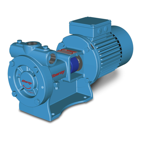
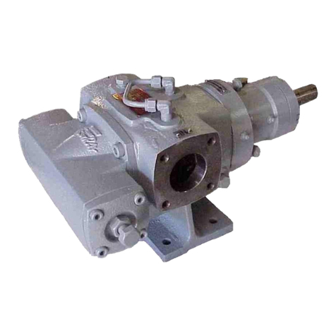
Ebsray R75 Guide

Publication No.: 2753-20
1
1.1 TABLE OF CONTENTS
1.1 TABLE OF CONTENTS 1
1.2 SAFETY DATA 1
1.3 ESSENTIAL HEALTH & SAFETY
REQUIREMENTS 1
SECTION 2 –PUMP DATA 2
2.1 PUMP IDENTIFICATION 2
2.2 TECHNICAL DATA 2
2.3 INITIAL PUMP START UP INFORMATION 2
SECTION 3 –INSTALLATION 3
3.1 INTRODUCTION 3
3.2 WARRANTY 3
3.3 TRANSPORTATION, HANDLING &
INSPECTION 3
3.4 PUMP LOCATION & PIPING
CONNECTIONS 3
3.5 ALTERNATE INLET 4
3.6 PRE-INSTALLATION CLEANING 4
3.7 PUMP ROTATION 4
3.8 CLOSE-COUPLED DRIVES 4
3.9 LONG COUPLED AND BELT DRIVES 4
3.10 PUMP INTERNAL RELIEF VALVE 4
3.11 COUPLING ALIGNMENT 4
SECTION 4 –OPERATION 5
4.1 PRE-STARTUP CHECKLIST 5
4.2 COMMISSIONING/STARTUP
PROCEDURE 5
4.3 PERIODIC INSPECTION 5
SECTION 5 –MAINTENANCE 6
5.1 ROUTINE MAINTENANCE AND
INSPECTION 6
5.2 MAINTENANCE –REPAIR AND
OVERHAUL 6
5.3 SPARE PARTS 6
5.4 INSPECTION UPON DISASSEMBLY 6
5.5 IMPELLER & MECHANICAL SEAL
REPLACEMENT 7
5.6 BEARINGS-SHAFT ASSEMBLY 8
REPLACEMENT
5.7 BEARING REPLACEMENT 8
5.8 VALVE & VALVE SPRING
REPLACEMENT
SECTION 6 –ADDITIONAL PROCEDURES 9
6.1 RE-HANDING THE PUMP 9
6.2 LOCKED IMPELLER VARIANT –9
IMPELLER REPLACEMENT
SECTION 7 –R75/R77PARTS DESIGNATION 10
SECTION 8 –R80/R82 PARTS DESIGNATION 12
SECTION 9 –TROUBLESHOOTING 14
1.2 SAFETY DATA
This is a SAFETY ALERT SYMBOL.
When you see this symbol on the product, or in the manual,
look for one of the following signal words and be alert to the
potential for personal injury, death or major property
damage.
Warns of hazards that WILL cause serious personal injury,
death or major property damage.
Warns of hazards that CAN cause serious personal injury,
death or major property damage.
Warns of hazards that CAN cause personal injury
or property damage.
NOTE:
Indicates special instructions which are very
important and must be followed.
1.3 ESSENTIAL HEALTH AND SAFETY
REQUIREMENTS
This publication is intended to assist those involved with the
installation, operation and maintenance of the R75, R77, R80
and R82 Regenerative Turbine Pumps and MUSTbe kept with
the pump.
Thoroughly review this manual, all instructions and hazard
warnings, BEFORE performing any installation, operation or
maintenance.
Maintain ALL system and Ebsray liquefied gas pump
operation and hazard warning decals.
This publication is TYPICAL ONLY.
Ebsray reserves the right to retract or alter this or any other
relevant documents at any time without notification. Ebsray
also reserves the right to determine the validity of any warranty
claims based on the proper application of Ebsray supplied
equipment by way of adherence to the specifications within this
publication and any other relevant Ebsray documents.
This Publication does NOT depict:
1. Ancillary required equipment related to the installation,
operation & maintenance of the Pump e.g. miscellaneous
flanges, fittings etc.
2. Required equipment unrelated to the pumpset e.g. tank fill
lines, vapour return lines, emergency shutdown systems etc.
3. The materialsandmethodoffabricationofanyrequired sub-
systems.
INSTALLATION, OPERATION &
MAINTENANCE INSTRUCTIONS
MODELS: R75, R77, R80 and R82
REGENERATIVE TURBINE PUMPS

Publication No.: 2753-20
2
It is the responsibilityof the designer, fabricator and the installer
of each required sub-system to ensure that:
a) The Ebsray specifications within this publication and any
other relevant Ebsray documents are STRICTLY
adhered to.
b) Any variation (including the use of equipment deemed
"Equivalent") or addition to Ebsray specifications, as
related to the pumpset and pumping system in general,
meet Ebsray's minimum requirements.
c) All design, fabrication and installation of the tank and
sub-systems is STRICTLY in accordance with all
relevant National, State and Local Directives,
Standards, Codes and Regulations.
d) All equipment is suitable for the hazardous area as defined
by EN6079.10.1
e) All Essential Health and Safety Requirements (EHSR’s) as
outlined in EN60079.14, EN15198, EN ISO 80079-36 and
EN ISO 80079-37 are adhered to.
f) All relevant requirements of NFPA 58 for UL Listed Models.
This product is CE marked (meaning the equipment has been
assessed and supplied in conformity to those Directives), strict
adherence with all instructions and recommendations forms an
essential part in maintaining the product/equipment’s conformity.
Failure to comply with the instructions and recommendations
contained in this Publication may void CE conformity.
SECTION 2 - PUMP DATA
2.1 PUMP IDENTIFICATION
A pump identification tag, containing the pump serial
number, I.D. number, and model designation, is attached to
each pump. It is recommended that the data from this tag
be recorded in SECTION 2.3. If replacement parts are
needed, or if information pertaining to the pump is required,
this data must be furnished to an Ebsray representative.
Some pump models are listed by Underwriters’ Laboratories
for LP Gas and/or Anhydrous Ammonia service.
2.2 TECHNICAL DATA
Minimum/Maximum
Operating Temperature
-40OC (-40OF)/
135°C (275°F)
Maximum Pump Speed
3500 RPM
Maximum Differential
Pressure
1400 kPa (14 Bar)
Maximum Working
Pressure for non-UL Listed
2920 kPa (29.2 Bar)
Maximum Working
Pressure for UL Listed
2760 kPa (27.6 Bar)
Technical Data is for standard materials of construction.
Consult Ebsray Material Specs for optional materials of
construction.
2.3 INITIAL PUMP START UP INFORMATION
Model No.
Serial No.
Equipment No.
Date of
Installation
Inlet Gauge
Reading
Discharge
Gauge Reading
Flow Rate
Failure to set the vehicle emergency
brake and chock wheels before
performing service can cause severe
personal injury or property damage
Failure to relieve system pressure prior
to performing pump service can cause
serious personal injury or property
damage. Systems with meters will still be
pressurized even after the hose is
emptied
Hazardous
machinery can
cause serious
personal injury.
Hazardous pressure
can cause serious
personal injury or
property damage
Failure to disconnect and lockout
electrical power or engine drive before
attempting maintenance can cause
severe personal injury or death
Operation without guards in place can
cause serious personal injury, major
property damage, or death.
Hazardous
machinery can
cause serious
personal injury.
Do not operate
without guard
in place
Disconnecting fluid or pressure
containment components during pump
operation can cause serious personal
injury or property damage.
Hazardous pressure
can cause serious
personal injury or
property damage

Publication No.: 2753-20
3
SECTION 3 - INSTALLATION
3.1 INTRODUCTION
NOTE:
Ebsray pumps must only be installed in systems designed
by qualified competent engineering personnel. System
design must conform to all applicable regulations and
codes and provide warning of all system hazards.
NOTE:
This installation must be performed by qualified,
competent personnel and they must, completely
read/review this entire document prior to starting any
work. If any part of this publication is unclear, obtain
clarification before proceeding with any work.
NOTE:
These instructions are additional to, and do not supersede
or override any applicable statutory, legal or regulatory
requirements.
NOTE:
New pumps contain residual test fluid and rust inhibitor. If
necessary, flush pump prior to use.
The design, materials and workmanship incorporated in the
manufacture of Ebsray pumps make them capable of reliable
operation over a long working life. Correct installation is
essential to ensure a long service life.
When the equipment supplied utilises components other than
those manufactured by Ebsray (e.g. electrical equipment,
switches, fittings or valves), refer to the original manufacturer's
data before installation or servicing is commenced. Failure to
observe these details may void the Warranty.
3.2 WARRANTY
All Ebsray manufacturedpumps and equipment are warrantedas
standard for one (1) year against faulty workmanship and/or
materials. Refer to Ebsray Pumps for details.
Ancillary equipment supplied by Ebsray but manufactured by
others are not covered under Ebsray’s warranty.
3.3 TRANSPORTATION, HANDLING & INSPECTION
Standard domestic packing is suitable for shipment in covered
transports. When received, inspect the pump/pumpset against
dispatch documentation and for damage.
Any damage or shortage incurred during transit should be noted
on the packing note and on both your own and the carrier's copy
of the consignment note.
Should a shortage be evident on receipt, notify Ebsray
immediately giving full details and packing note number.
Additionally a claim should be made with the transport company.
When received on site the pump set must be stored in a dry
covered area. NOTE:
Never allow water or any corrosive product to enter the
pump. Hydrostatic testing of pipework with pump installed
may void the Warranty.
If the pump/pumpset is not installed and commissioned
immediately or has been removed from service, then the pump
internals should be filled or thoroughly flushed with a light rust
inhibiting hydrocarbon fluid, In addition to this pump ports must
be sealed to exclude ingress of condensation, moisture or foreign
material.
3.4 PUMP LOCATION & PIPING CONNECTIONS
The R75, R77 R80 and R82 are designed to mount directly or
remotely to the supply tank’s commercial internal control valve.
Pump life and performance will be significantly reduced when
installed in an improperly designed system. Before starting the
layout and installation of the piping system, review the
following:
1. When locating the pump, safety MUST be the first
consideration.
2. The discharge hose and fittings should be large enough
to minimize the pressure drop in the system. The lower
the friction loss, the higher the flow rate.
3. All piping and fittings MUST be properly supported to
prevent any piping loads from being placed on the pump.
Debris left in pipework will cause
significant damage to the pump and will
void the warranty.
Foreign matter entering the pump WILL
cause serious damage to the pump
Foreign matter
entering the pumps
inlet will cause
serious damage
Flush tank and
supply piping prior
to installing pump
Due care must be used when handling
the pump. Failure to do so may result in
serious personal injury or property
damage.
Follow all lifting
codes and do not
drop the pump

Publication No.: 2753-20
4
4. Check alignment of pipes to pump to avoid strains which
might later cause misalignment. See Figure 1. Unbolt
flanges or break union joints. Pipes should not spring away
or drop down. After pump has been in operation for one to
two weeks, completely recheck alignment.
NOTE:
Pumps with welded connections contain non-metallic O-
ring seals that will be damaged if welding is done with
these O-rings installed.
Prior to welding the piping, remove the O-rings from under the
alternate inlet flange and discharge flange. After the welding is
complete, reinstall the lubricated O-rings into the cleaned O-
ring grooves.
3.5 R75/R77 - ALTERNATE INLET
The R75 and R77 have an alternate inlet port can be used as a
fill connection for bottom loading of the tank by stationary
pumps at the terminal or bulk plant. It can also be used as an
alternate pump inlet, allowing the pump to unload another tank.
The Alternate Inlet can be used to remove liquid from end user
tanks prior to removal/inspection. As such, it is recommended
that Alternate Inlet must be connected through a suitable
strainer using a minimum 40 mesh strainer screen.
To minimize vapor formation, the alternate inlet line must
minimum DN50 and as short as possible.
3.6 PRE-INSTALLATION CLEANING
NOTE:
New pumps contain residual test fluid and rust inhibitor. If
necessary, flush pump prior to use.
The supply tank and intake piping MUST be cleaned and
flushed prior to pump installation and operation.
3.7 PUMP ROTATION
NOTE:
Confirm pump rotation by checking the pump rotation
arrows respective to pump driver rotation.
The pump rotation is always clockwise looking from the shaft
end. See SECTION 6.1 for instructions for re-handing the
pump.
3.8 CLOSE-COUPLED DRIVES
R75, R77, R80 and R82 pumps are designed to be close
coupled to hydraulic motors and electric motors. The motors
should be well supported with their shafts parallel to the pump
shaft in all respects.
Ebsray can provide optional close-coupled hydraulic motor and
electric motor adapters. These adapters provide straight
alignment of the motor drive through a coupling connected to a
straight key pump shaft.
3.9 LONG COUPLED AND BELT DRIVES
The R80 and R82 pumps are also designed to be long coupled
driven and belt driven.
Long coupled drives should be well supported with their shafts
parallel to the pump shaft in all respects.
Belt drives should be well supported with their shafts parallel to
the pump shaft and should minimise radial load on the pump
shaft.
3.10 PUMP INTERNAL RELIEF VALVE
NOTE:
When fitted, the pump internal relief valve is designed to
protect equipment from excessive pressure and must not
be used as a system pressure control valve or operational
bypass valve.
NOTE:
Non-UL Listed Pumps (e.g. ATEX Marked Pumps) are
normally supplied without the internal relief valve (Blank-
No Valve is marked on the pump). An external pressure
limiting system valve is required for these variants.
For ALL liquefied gas applications, install an external bypass
valve which must have a free and clear passage back to the
tank.
DO NOT pipe the External Bypass Valve back into the pumps’
inlet line.
External Bypass Valves are vital to the performance and
operation of liquefied gas pumps and control the maximum
operating differential pressure of the system.
If the pump is fitted with an Internal Relief Valve, the
differential pressure setting on the external bypass valve must
not exceed 1400 kPa (14 Bar).
3.11 COUPLING ALIGNMENT
To maximise the life of the pump appropriate alignment of the
coupled shafts is a fundamental requirement of any coupling
installation. If pump was supplied byEbsray as part of a pumpset
unit, pump and driver have been accurately aligned at factory.
To ensure that alignment has been maintained during transit and
installation,
alignment MUST
BE CHECKED
upon final
installationandprior
to startup.
Ensure ‘distance
between shaft ends’
(DBSE) is correct for the type of coupling utilised.
Angular misalignment
As shown in Figure 2 where shafts are at an angle to one
another should be corrected before parallel misalignment.
Parallel misalignment
As shown in Figure 3
where shafts are in line
angularly and parallel to
each other but are offset
must be corrected.
Figure 1:
Pipe alignment
Figure 2
Figure 3

Publication No.: 2753-20
5
SECTION 4 - OPERATION
4.1 PRE-STARTUP CHECKLIST
a) Check the alignment of the pipes to the pump. Pipes
must be supported so that they do not spring away or
drop down when the pump flanges or union joints are
disconnected.
b) Install pressure gauges in the 1/4" NPT ports located
on the pump casing. These can be used to check the
actual inlet and discharge conditions after pump start-
up.
c) Inspect complete piping system to ensure that no
piping loads are being placed on the pump.
d) Secure appropriate hose connections. Check entire
piping system not leaking.
e) Check shaft rotation and freedom of shaft rotation.
f) Open inlet and discharge valves.
4.2 COMMISSIONING/STARTUP PROCEDURE
1. Open the shut-off valve in the bypass return line.
2. Open the tank outlet valve (same as pump inlet valve).
3. Start the pump. Confirm proper pump rotation by
checking the pump rotation arrow on the cover.
4. Check the pump speed. Pump speed must never
exceed the recommended maximum. Refer to SECTION
2.2 of this manual.
5. Check the pressure gauges to ensure the system is
operating within expected parameters. Record the
gauge readings in SECTION 2.3 of this manual for future
reference.
6. Inspect piping, fittings, and associated system
equipment for leaks, noise, vibration and overheating.
7. Close the discharge valve and check the differential
pressure. It must not exceed the pressure setting of the
external bypass valve.
8. Inspect pump frequently during the first few hours of
operation for such conditions as excessive heating of
ball bearings, vibration or unusual noises.
NOTE:
Consult SECTION 9 of this manual if difficulties during
start up are experienced and troubleshooting is required.
4.3 PERIODIC INSPECTION
Periodic inspection of the Pump, Pump System and Ancillary
Equipment is required to maintain safety, conformity,
operational functionality and reliability.
If any abnormal condition is discovered, cease operation of
pump immediately and take action to rectify the problem.
For safe operation, the following items should be included in the
routine periodic inspection:
1. Inspect the system for leaks, vibration, abnormal noises,
and signs of overheating or discolouration.
2. Inspect coupling assembly for signs of wear, overheating
or discolouration
3. Check Pump differential pressure
4. Check Motor Current.
5. Inspect motor for vibration, abnormal noises, and signs of
overheating or discolouration.
Operation without guards in place can
cause serious personal injury, major
property damage, or death.
Do not operate
without guard
in place
Failure to relieve system pressure prior
to performing pump service can cause
serious personal injury or property
damage. Systems with meters will still
be pressurized even after the hose is
emptied
Hazardous pressure
can cause serious
personal injury or
property damage
Disconnecting fluid or pressure
containment components during pump
operation can cause serious personal
injury or property damage.
Hazardous pressure
can cause serious
personal injury or
property damage
Pumps operating against a closed valve
can cause system failure, personal
injury and property damage
Hazardous pressure
can cause personal
injury or property
damage

Publication No.: 2753-20
6
Table 1: Torque required for bolted connections
SECTION 5 - MAINTENANCE
Failure to set the vehicle emergency
brake and chock wheels before
performing service can cause severe
personal injury or property damage.
Failure to relieve system pressure prior
to performing pump service can cause
serious personal injury or property
damage. Systems with meters will still
be pressurized even after the hose is
emptied
Hazardous
machinery can
cause serious
personal injury.
Hazardous pressure
can cause serious
personal injury or
property damage
Failure to disconnect and lockout
electrical power or engine drive before
attempting maintenance can cause
severe personal injury or death
Disconnecting fluid or pressure
containment components during pump
operation can cause serious personal
injury or property damage.
Hazardous
machinery can
cause serious
personal injury.
Hazardous pressure
can cause personal
injury or property
damage
5.1 ROUTINE MAINTENANCE AND INSPECTION
NOTE:
Maintenance shall be performed by qualified technicians
only, following the appropriate procedures and warnings
as presented in this manual.
Routine maintenance and inspections can be performed with the
pump ‘in-situ’, so long as complete isolation, depressurising and
purging procedures have been completed. However for
repair/overhaul, it is recommended that the pump be removed
from the installation.
The R75, R77, R80 and R82 ball bearings are sealed for life. As
such there are NO routine maintenance requirements.
Ebsray recommends a maximum interval of three months or 500
hours operation between routine inspections (More frequent
inspections may be necessary dependent upon usage, site
conditions, and operation). These inspections should include
(but not limited to) checking for;
. Leakage from the pump, pipework, valves etc.
Excess vibration/noise.
Excessive heat from the Pump or hydraulic system.
5.2 MAINTENANCE –REPAIR AND OVERHAUL
If the pump is being sent to Ebsray for maintenance or repair the
pump must be fully flushed out i.e. returned in the state it was
provided.
Numbers in parentheses (i.e. Cover (2)) following individual parts
indicate reference numbers specified in SECTION 7 and 8.
Steps before disassembly
1. Obtain the appropriate Work Permit if required.
2. Isolate power supply to motor –if fitted.
3. Isolate pump from liquids in inlet and discharge lines,
depressurise and purge out any toxic, flammable, corrosive
or air hardening liquids (if present).
Once the pump is removed from the pipework, flange O-rings and
gaskets cannot be re-used.
Short video tutorials are available on the Ebsray pumps website
covering main maintenance tasks.
Tools required for maintenance:
Metric Allen key set
Metric socket drive
Allen key set
Torque wrench
Small flat head screwdriver
Short (100mm long)
piece of 1-1/4 inch
schedule 40 pipe
Soft head mallet
External circlip pliers
2 off M8x75 setscrews
Before any re-assembly ensure all parts are deburred and cleaned.
All O-rings MUST be replaced when any disassembly occurs.
5.3 SPARE PARTS
When ordering spare parts, to minimise pump downtime,
ALWAYS quote the pump Serial Number located on the
nameplate of the pump or SECTION 2.3 of this publication.
NOTE:
Substitute or so-called ‘equivalent’ spare parts are not to
be used. Safe operation and pump performance may be
severely compromised if any substitute parts are used.
The use of substitute parts may void the warranty.
5.4 INSPECTION UPON DISASSEMBLY
1. Check Impeller (3) and seal zone of the Bearing Housing
(20) for damage or wear. Replace Impeller if blades have
been damaged or wear exceeds minimum recommended
dimensions:
Minimum R75/R80 Impeller width is 21.70mm
Minimum R77/R82 Impeller width is 24.70mm
Minimum outside diameter is 155.75mm.
2. Check Shaft for wear, damage or run-out. Replace as
required.
3. Inspect both Bearings for wear. It is recommended during
major overhauls that Bearingsbe replaced.Ball bearings are
to be replaced after 50,000 operational hours.
4. Check Mechanical Seal components for wear or damage. It
is recommended during major overhauls that Mechanical
Seal components be replaced.
Metric
setscrew size
Torque required
in Nm (ft-lbs)
M12
100 (75)
M10
58 (43)
M6
13 (10)
M5
7 (5)

Publication No.: 2753-20
7
5.5 IMPELLER & MECHANICAL SEAL REPLACEMENT
The pump should rest on its inlet flange.
1. Remove the Cover’s eight cap head setscrews (6). If
required fit two of the setscrews to the tapped jacking
holes.
2. Remove the Cover (2), remove the Cover O-ring (4),
discard and replace with lightly lubricated new O-ring.
NOTE:
The cover is a very neat fit into the pump body. Do not use
excessive force to remove the cover. If the cover gets stuck,
gently rock loose or gently tap loose with a soft mallet.
NOTE:
The impeller is ‘floating’ on the shaft for most applications
For certain applications, Ebsray specifies that the Impeller is
to be locked to the shaft via a socket set screw in the impeller.
The locked impeller variants are shown with an “L”in the
model number - example R80-C33B-1FL1-Y1V2R-P0
The following instructions are for a floating Impeller.
Refer to Section 6.2 for removal and replacement of the locked
Impeller.
3. Remove the Impeller (2) andImpeller Key (8). If required,
use 2 off M8x75mm setscrews as jacking screws in the
Impeller’s taped holes.
4. Remove the Circlip (58). At this point you can remove the
dynamic element by using two of the four cartridge cap
head setscrews (57A)and fitthem to the back of the Seal
Sleeve (42) (part of the dynamic element (56)) and use
as extraction screws. If replacing the entire seal follow
steps below.
5. Remove the cartridge cap head setscrews and screwtwo
of them into the Mechanical Seal Cartridge’s (57) tapped
jacking holes. Jack the Cartridge and/or Mechanical Seal
Assembly (56) off the shaft.
6. Remove the dynamic element (41, 42, 45, 45A, 46
assembled) and Seal Seat (40) from the Cartridge.
Remove the O-rings (57B & C) from the Cartridge and
discard.
7. Fit a small screwdriver or punch to
the Cartridge’s holes and gently tap
the Lip Seal (55) out (See Figure 4).
8. Clean the Cartridge using non-
residual contact cleaner or similar.
9. Loosely fit the new Lip Seal to the
Cartridge (with the lip facing out,
See Figure 5). Using the piece of 1-
1/4 inch pipe as a drift, gently tap the
Lip Seal into the Cartridge. Ensure
that the Lip Seal is flat (flush) by
checking the holes in the back of the
Cartridge.
10. Fit the smallest new O-ring (48) to
the Seal Seat and lightly lubricate.
11. Without removing the protective cover, press the Seal
Seat into the Cartridge with fingers (ensuring complete
and square engagement).
12. Remove the protective cover from the Seal Seat, clean
with non-residue contact cleaner.
13. Fit the new O-rings (57B & 57C) to the Cartridge and
lightly lubricate. The smaller cross section O-ring goes
on the back.
14. Lightly lubricate the Cartridge O-rings, Lip Seal and bore
of the Bearing Housing (20).
15. Aligning the four holes of the Cartridge with the tapped
holes in Bearing Housing, fit the Cartridge to the
Bearing Housing.
16. Fit the four Cartridge cap head setscrews with ‘Loctite
243’ or similar and tighten to 7N-m (5ft-lbs).
17. Remove the protective cover from the dynamic
element and clean face with non-residual contact
cleaner. Lightly lubricate the new internal Shaft O-ring
(46) and lubricate seal face with clean light machine
oil.
18. Aligning the dynamic element pin
with the Impeller’s keyway, fit the
dynamic element onto the shaft
and rest gently on the Seal Seat’s
face.
19. Loosely fit the Circlip (58) onto the
shaft.Using the 1-1/4 inch pipe as a
press tool, snap the circlip into
place. Ensure the Circlip is correctly
seated (See Figure 6).
20. Fit the new Impeller Key (8) to the keyway. Aligning the
Impeller keyway to the shaft key, fit the Impeller to the
shaft.
NOTE:
Correct angular orientation of both the cover and bearing
housing is guaranteed as one of the bolt holes is 1.5 degrees
out of pitch. In other words if all eight bolts do not start in the
Body’s tapped holes the angular orientation is not correct.
21. Gently fit the Cover (2) to the Body(1).
Do not force the cover into the body.
If it gets stuck, gently rock loose or
gently tap it in with a soft mallet.
22. Do a final check to ensure the Cover
O-ring (4) is correctly located (See
Figure 8), then hand fit the eight cover
cap head setscrews (6). Torque
setscrews to 100Nm (75 ft-lb’s)
Figure 4
Figure 5
Figure 8

Publication No.: 2753-20
8
5.6 SHAFT-BEARING ASSEMBLY REPLACEMENT
The Bearing-Shaft Assembly Includes:
Shaft (21)
Inspection End Bearing (23)
Drive End Bearing (24)
Circlip (25)
To replace the Bearing-Shaft complete steps one to five in
SECTION 5.5, then complete the following steps:
1. Remove the Driver Key (34).
2. Remove the Bearing Cap’s (99) eight cap head
setscrews (99B). Remove the Bearing Cap, remove
the Bearing Cap’s O-ring (99A), discard and replace
with lightly lubricated new O-ring.
3. Replace the Bearing Dust Seal (33)
4. Push or gently tap the Impeller end of the Shaft (21)
and Bearing’s fixed assembly from the Bearing
Housing.
To replace bearings see Section 5.7 below.
5. GentlytaporpressthedrivenendofthenewBearing-
Shaft Assembly into the Bearing Housing until the
drive end bearing’s outer race is fully seated in the
Bearing Housing.
6. Fit the Bearing Cap over the driven end of the Shaft.
Check the Bearing Cap’s O-ring is correctly located
before, hand fitting the eight cap head setscrews.
Torque the setscrews to 13 Nm (10 ft-lb’s).
7. Replace the Driver Key. Continue on with step six of
SECTION 5.5.
5.7 BEARING REPLACEMENT
A press and two pieces of flat bar are required to remove the
Shaft (21) and Bearing’s fixed assembly from the Bearing
Housing and also to remove and replace the Bearings from the
Shaft.
1. To replace the Drive End Bearing (DEB, 24) and the
Inspection End Bearing (IEB, 23) complete steps one
to five in SECTION 5.6, then complete the following
steps: Remove the Bearing Circlip (25), starting with
the DEB, support the Impeller side of the DEB’s inner
raceway and press the driven end of the Shaft until
the DEB is pushed off the Shaft.
2. Then support the driven side of the IEB and press
from the Impeller end of the Shaft. Press until the IEB
is pushed off the Shaft.
3. To press the IEB onto the
Shaft fully support the inner
raceway of the IEB using
two pieces of flat bar (See
Figure 9). Locate the
Impeller end of the Shaft
(Impeller has a 10mm wide
keyway) through the IEB.
Press the driven end of the
shaft until it fully rests on its
shoulder.
4. To press the DEB onto the Shaft, fully support the
inner raceway of the DEB and press the Impeller end
of the Shaft onto the DEB. Press the Impeller end of
the Shaft until the circlip groove is fully exposed.
5. Fit the Bearing Circlip
5.8 VALVE & VALVE SPRING REPLACEMENT
NOTE:
Some Pump variants do not have an integral valve and the
passage in the body is blocked off with a blanking plug.
The blanking plug is maintenance free.
1. Remove the four Valve Cover cap head setscrews
(103B).
2. Remove the Valve Cover.
3. Discard the Valve Cover O-ring (103A), and replace
with a lightly lubricated new O-ring.
4. Remove the Bypass Spring. Then remove the Valve
(105). If the Valve is stuck use pliers or similar to pull
the Valve out.
NOTE:
Be careful not to scratch the Valve with the pliers as any
foreign materials left inside the pump WILL seriously
damage the pump.
5. Fit the new Valve into the Body
6. Loosely fit Bypass Spring into the Valve Cover.
7. Fit the Bypass Spring/Valve Cover to the Body
ensuring that the Bypass Spring Locates onto the
Valve’s boss.
8. Ensuring the valve cover O-ring is located properly,
hand fit the four Valve Cover cap head setscrews.
Torque setscrews to 58 Nm (43 ft-lbs)
Figure 9

Publication No.: 2753-20
9
SECTION 6 –ADDITIONAL PROCEDURES
6.1 RE-HANDING THE PUMP
R75/R77 - Looking at the pump from the shaft end with the
inlet flange up, the Pump can be configured with the
alternate inlet on the left or the right.
R80/R82 –Looking at the pump from the shaft end with the
mounting feet down, the Pump can be configured with the
inlet port on the right or the left.
1. Remove the eight cover cap head setscrews (6).
2. If required, fit two of the setscrews to the tapped
jacking holes and tighten to remove cover.
3. Remove the Cover (2), remove the Cover O-ring (4),
discard and replace with lightly lubricated newO-ring.
NOTE:
The cover is a very neat fit into the pump body. Do not
use excessive force to remove the cover. If the cover
gets stuck, gently rock loose or gently tap loose with a
soft mallet.
4. Lightly lubricate and refit to Cover, ensure that the O-
ring is properly fitted.
5. Remove the Impeller from the shaft as the Impeller
may slide off the shaft during the Bearing Housing
removal and re-fitment.
6. Remove the eight bearing housing cap head
setscrews (27). Repeat step two if required.
7. Remove the Bearing Housing (20), remove the
BearingHousingO-ring(26),discardandreplacewith
lightly lubricated new O-ring.
8. Lightly lubricate and refit to the Bearing Housing,
ensure that the O-ring is properly fitted.
9. Refit the Bearing Housing to the opposite side of the
pump. The Bearing Housing inlet port aligns to the
Body (1) inlet port.
NOTE:
Correct angular orientation of both the Cover and Bearing
Housing is guaranteed as one of the bolt holes is 1.5
degrees out of pitch. In other words if all eight bolts do
not start in the Body’s tapped holes, the angular
orientation is not correct.
10. Do not force the Bearing Housing into the Body. If it
gets stuck, gently rock loose or gently tap in with a
soft mallet.
11. Do a final check to ensure the Bearing Housing O-
ring is correctly located.
12. Fit all eight bearing housing cap head setscrews and
torque to 100 Nm (75 ft-lbs).
13. Aligning the Impeller keyway to the shaft key, fit the
Impeller to the shaft.
14. Fit the Cover to Body, note that the raised cast text
“IN” aligns with the Body’s inlet flange. Again beware
the close fit and don’t force the cover in. Again check
that the Cover O-ring is correctly located.
15. Fit all eight cover cap head setscrews and torque to
100 Nm (75 ft-lbs).
6.2 LOCKED IMPELLER REPLACEMENT
The pump should rest on its inlet flange.
1. Remove the Cover’s eight cap head setscrews (6). If
required fit two of the setscrews to the tapped jacking
holes.
2. Remove the Cover (2), remove the Cover O-ring (4),
discard and replace with lightly lubricated newO-ring.
NOTE:
The cover is a very neat fit into the pump body. Do not use
excessive force to remove the cover. If the cover gets
stuck, gently rock loose or gently tap loose with a soft
mallet.
3. Loosen the Impeller’s locking screw (10) and remove
the Impeller (2) and Impeller Key (8). If required, use
2 off M8x75mm setscrews as jacking screws.
4. Rotate the Shaft (21) such that the impeller keyway is
at the 3 o’clock position. Fit the new Impeller Key (8)
to the keyway.
5. To set the Impeller (3)
clearance, tape 2 off
0.005 inch (0.127mm)
feeler gauges as
shown in Figure 7
such that the ends
come up against the
shaft.
6. Fit the Impeller to the
shaft and then fit the
M8x12 socket set
locking screw tightly
to the Impeller with
Loctite 243 or equal.
NOTE:
The feeler gauges must be aligned horizontally at 9
o’clock & 3 o’clock. While applying even pressure to the
Impeller, tighten the locking screw.
7. Remove the feeler gauges. If they are tight or stuck
gently tap the shaft on the opposite side while pulling
the feeler gauges.
8. Gently fit the Cover (2) to the Body(1).
Do not force the cover into the body.
If it gets stuck, gently rock loose or
gently tap it in with a soft mallet.
9. Do a final check to ensure the Cover
O-ring (4) is correctly located (See
Figure 8), then hand fit the eight cover
cap head setscrews (6). Torque
setscrews to 100Nm (75 ft-lb’s)
Figure 8
Figure 7
9 O’CLOCK
POSITION
3 O’CLOCK
POSITION
KEYWAY

Publication No.: 2753-20
10
SECTION 7 –R75/R77 PARTS DESIGNATION
Cat#
Description
Qty.
Cat#
Description
Qty.
1
Body
1
48
O-ring - Seal Seat
1
2
Cover
1
55
Lip Seal - Secondary seal
1
3
Impeller
1
56
Mechanical Seal Assembly
1
4
O-ring - Cover
1
57
Cartridge - Mechanical seal
1
6
Cap Head Setscrew
8
57A
Cap Head Setscrew
4
7
Plug - Gauge Tapping
2
57B
O-ring - Cartridge primary
1
8
Key - Impeller
1
57C
O-ring - Cartridge secondary
1
10
Socket setscrew
1
58
Circlip - Mechanical seal
1
20
Bearing Housing
1
99
Bearing Cap
1
21
Shaft
1
99A
O-ring - Bearing Cap
1
23
Ball Bearing - Inspection end
1
99B
Cap Head Setscrews
8
24
Ball Bearing - Drive end
1
100
Adaptor Flange - Straight
1
25
Circlip - Bearing
1
100A
O-ring - Adaptor Flange
2
26
O-ring - Bearing Housing
1
100B
Cap Head Setscrews
8
27
Cap Head Setscrew
8
101
Adaptor Flange - Elbow
1
33
Dust Seal - Bearing
1
101A
Adaptor Flange - Elbow Plug
1
34
Key - Driver
1
102
Blanking Flange
1
40
Seal Seat
1
103
Valve Cover
1
41
Seal Face
1
103A
O-ring - Valve cover
1
42
Seal Sleeve
1
103B
Cap Head Setscrews
4
45
Seal Spring
6
104
Bypass spring
1
45A
Spring Retainer
1
105
Valve
1
46
O-ring - Shaft
1
109
Valve Blanking Plug (Optional)
1
47
O-ring –Seal Sleeve
1
109A
Valve Blanking Plug O’ring (Optional)
1
Adaptor Flange Options
Alternate Inlet
Discharge
Blanking Flange Kit
100
Adaptor Flange (Straight) - 2” NPT
100
Adaptor Flange (Straight) - 2” NPT
100
Adaptor Flange (Straight) - Slip-on weld
100
Adaptor Flange (Straight) - Slip-on weld
101
Adaptor Flange (Elbow) - 2” NPT
Adaptor Flange - 2 1/2" NPT
101
Adaptor Flange (Elbow) - 2” NPT
Adaptor Flange - 2 1/2" NPT
101
Adaptor Flange (Elbow) - Slip-on weld
101
Adaptor Flange (Elbow) - Slip-on weld
102
Blanking Plate (Mild Steel)
110
Nozzle DN80 ANSI 300/3” NPT
102
Blanking Plate (Ductile Iron)
110A
O’ring - Nozzle

Publication No.: 2753-20
11

Publication No.: 2753-20
12
SECTION 8 –R80/R82 PARTS DESIGNATION
Cat#
Description
Qty.
Cat#
Description
Qty.
1
Body
1
48
O-ring - Seal Seat
1
2
Cover
1
55
Lip Seal - Secondary seal
1
3
Impeller
1
56
Mechanical Seal Assembly
1
4
O-ring - Cover
1
57
Cartridge - Mechanical seal
1
6
Cap Head Setscrew
8
57A
Cap Head Setscrew
4
7
Plug - Gauge Tapping
2
57B
O-ring - Cartridge primary
1
8
Key - Impeller
1
57C
O-ring - Cartridge secondary
1
10
Socket setscrew
1
58
Circlip - Mechanical seal
1
20
Bearing Housing
1
99
Bearing Cap
1
21
Shaft
1
99A
O-ring - Bearing Cap
1
23
Ball Bearing - Inspection end
1
99B
Cap Head Setscrews
8
24
Ball Bearing - Drive end
1
100B
Cap Head Setscrews
8
25
Circlip - Bearing
1
103
Valve Cover
1
26
O-ring - Bearing Housing
1
103A
O-ring - Valve cover
1
27
Cap Head Setscrew
8
103B
Cap Head Setscrews
4
33
Dust Seal - Bearing
1
104
Bypass spring
1
34
Key - Driver
1
105
Valve
1
40
Seal Seat
1
109
Valve Blanking Plug (Optional)
1
41
Seal Face
1
109A
Valve blanking Plug O’ring (Optional)
1
42
Seal Sleeve
1
110
Nozzle DN80 ANSI 300/3” NPT
2
45
Seal Spring
6
110A
O-ring - Nozzle
2
45A
Spring Retainer
1
46
O-ring - Shaft
1
47
O-ring –Seal Sleeve
1

Publication No.: 2753-20
13

Publication No.: 2753-20
14
SECTION 9 –TROUBLESHOOTING
Symptom
Possible cause
Symptom
Possible cause
No Liquid
Delivery
No power to drive shaft
Coupling damaged or disengaged
Foreign matter in the pump
Ball Bearings seized
Inlet/Discharge valves closed
No liquid in supply tank
Incorrect direction of rotation
Strainer blocked
High static discharge pressure
Inadequate NPSHA
Pump vapour lock
Reduced
Output
Incorrect driver speed
Faulty driver
Discharge piping restricted
Strainer blocked
Inlet piping too small or too long
Foreign object in suction line
External bypass pressure setting too low
End of service life or adverse pumping
conditions
Excessive
Power
Consumption
Foreign matter in discharge line
Collapsed or kinked discharge hose
Pressure, Viscosity, Temperature or
Speed not as per design conditions
Foreign matter jamming parts
Pump out of alignment with driver
Parts worn
End of service life or adverse
pumping conditions
Excessive
Noise
Foreign matter jamming parts
Parts worn
End of service life or adverse pumping
conditions
Incorrect driver speed
Faulty or incorrect size driver
Leakage
from Pump
Seals incorrectly installed
Excessive dry running or pump
O-rings nicked, cut or twisted
O-rings not compatible with liquid
Worn or damaged shaft in seal zone
Misalignment causing excessive
shaft distortion
Excess system pressure
O-ring failure
Fasteners not tightened to specified
torque.
Thermal expansion of product when
locked between valves either side of
pump
Excessive static pressure
Seal faces cracked, scratched, pitted
or dirty
Visit www.ebsraypumps.com.au for more information on any Ebsray products
156 South Creek Rd, Cromer 2099, Australia
Telephone: (+612) 9905 0234 | Fax: (+612) 9938 3825
This manual suits for next models
3
Table of contents
Other Ebsray Water Pump manuals