Ebsray R SERIES Guide

Publication # 1852-04 EN
EBSRAY PUMPS
INSTALLATION, OPERATION &
MAINTENANCE INSTRUCTIONS
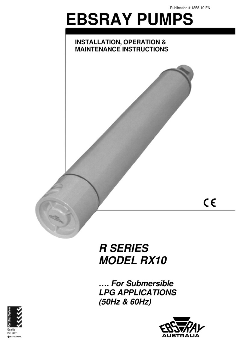
R SERIES
MODEL RX10
…. For Submersible
LPG APPLICATIONS
(50Hz & 60Hz)

2
CONTENTS
SECTION 1 - GENERAL ................................................................................................................................................4
1.1 INTRODUCTION.....................................................................................................................................4
1.2 TRANSPORTATION AND PACKING ....................................................................................................4
1.3 RECEIVING INSPECTION.....................................................................................................................4
1.4 HANDLING..............................................................................................................................................4
1.5 WARRANTY............................................................................................................................................4
SECTION 2 - SYSTEM DESCRIPTION.........................................................................................................................5
2.1 EBSRAY RX10 SUBMERSIBLE LPG PUMPING SYSTEM..................................................................5
2.2 EBSRAY RX10 SUBMERSIBLE PUMPSET..........................................................................................5
2.3 "THREE-TIER" PROTECTION SYSTEM...............................................................................................5
2.4 PPVVALVE (POSITIVE PRESSURE VENTILATION VALVE)...........................................................6
2.5 BYPASS VALVE - EBSRAY MODEL RV18 NRV..................................................................................6
2.6 DIFFERENTIAL PRESSURE SWITCH..................................................................................................6
2.7 CONTROL CONSOLE............................................................................................................................6
2.8 EBSRAY LPG SYSTEM CONTROLLER...............................................................................................6
2.9 LIST OF SYSTEM COMPONENTS .......................................................................................................6
a) COMPONENTS SUPPLIED BY EBSRAY ........................................................................................6
b) COMPONENTS SUPPLIED BY OTHERS.........................................................................................7
SECTION 3 - INSTALLATION .......................................................................................................................................8
3.1 LOCATION..............................................................................................................................................8
3.2 PUMPSET INSTALLATION....................................................................................................................8
3.3 PORT ALIGNMENT................................................................................................................................8
3.4 DISCHARGE RISER...............................................................................................................................8
3.5 ELECTRICAL CONDUIT ........................................................................................................................9
3.6 PUMP AND SYSTEM PIPING CONNECTIONS ...................................................................................9
3.7 RECOMMENDED ORDER OF ASSEMBLY..........................................................................................9
3.8 LPG/PRODUCT DISCHARGE PIPE FITTINGS..................................................................................11
3.9 DIFFERENTIAL PRESSURE SWITCH................................................................................................11
3.10 BYPASS VALVE...................................................................................................................................11
3.11 PPVVALVE ......................................................................................................................................12
3.12 LEAK CHECK .......................................................................................................................................12
3.13 ELECTRICAL CONNECTIONS - PUMPSET AND SYSTEM..............................................................12
3.14 JUNCTION BOX ...................................................................................................................................12
3.15 DIFFERENTIAL PRESSURE SWITCH (DPS).....................................................................................13
3.16 CONNECTING CABLE.........................................................................................................................13
3.17 CONTROL CONSOLE..........................................................................................................................13
SECTION 4 - OPERATION ..........................................................................................................................................14
4.1 DESCRIPTION......................................................................................................................................14
4.2 LUBRICATION......................................................................................................................................14
4.3 PRE-STARTUP CHECKLIST...............................................................................................................14
4.4 STARTUP PROCEDURE.....................................................................................................................14
SECTION 5 - CONTROL CONSOLE - DESCRIPTION, OPERATION & ADJUSTMENT.........................................16
5.1 OPERATIONAL FEATURES OF THE CONTROL CONSOLE - a) FASCIA......................................17
5.2 OPERATIONAL FEATURES OF THE CONTROL CONSOLE - b) INTERIOR .................................19
SECTION 6 - MAINTENANCE.....................................................................................................................................22
6.1 INSPECTION ........................................................................................................................................22
6.2 SERVICE...............................................................................................................................................22
6.3 SERVICE EXCHANGE.........................................................................................................................22
6.4 SPARE PARTS.....................................................................................................................................22
SECTION 7 - TROUBLE SHOOTING...................................................................................................................23 - 27
SECTION 8 - APPENDICES
APPENDIX A TYPICAL INSTALLATION P &ID
APPENDIX B RX10 OUTLINE DIMENSIONS AND SPECIFICATION
APPENDIX C TYPICAL WIRING SCHEMATIC AND CONNECTION DIAGRAM
APPENDIX D PRE-STARTUP COMMISSIONING CHECKLIST
APPENDIX E INSPECTION LOG
APPENDIX F COPIES OF CERTIFICATIONS & DECLARATIONS FOR RX10 PUMP/MOTOR

3
DANGE
R
WARNING
EBSRAY PUMPS Pty. Ltd.
628 PITTWATER ROAD PHONE: (+61 2) (9905 0234)
BROOKVALE NSW 2100 AUSTRALIA FAX: (+61 2) (9938 3825)
www.ebsraypumps.com.au
IMPORTANT NOTES
1. This Publication is TYPICAL ONLY and only relates to the specifications of the minimum equipment required to
ensure the optimum performance, maximum life and trouble-free operation of the Ebsray RX10 - 3.7 kW
Submersible Pumpset and the pumping system in general.
2. Products with the mandatory European CE mark affixed indicate conformity to the essential health and safety
requirements via their applicable EU Directives (eg. ATEX 94/09/EC, Machinery 98/37/EC etc).
As certain specific products/equipment outlined in this Publication are CE marked (meaning the equipment has
been assessed and supplied in conformity to those Directives), STRICT ADHERENCE with ALL the
Instructions and Recommendations forms an essential part in maintaining the product/equipment’s conformity.
Failure to comply with the Instructions and Recommendations contained in this Publication may void
CE conformity.
3. This Publication does NOT depict:
a) Ancillary required equipment related to the fabrication, installation and operation of the pumpset e.g.
miscellaneous flanges, fittings etc.
b) Required equipment unrelated to the pumpset e.g. tank fill lines, vapour return lines, emergency shutdown
systems etc.
c) The materials and method of fabrication and/or installation of the tank and required sub-systems.
4. It is the responsibility of the designer, fabricator and the installer of each actual tank and required sub-systems to
ensure that:
a) The Ebsray specifications within this Publication and any other relevant Ebsray Documents are STRICTLY
adhered to.
b) Any variation (including use of equipment deemed "Equivalent") or addition to the Ebsray Specifications, as
related to the Pumpset and pumping system in general, meet Ebsray's Minimum requirements.
c) All design, fabrication and installation of the tank and sub-systems is STRICTLY in accordance with all relevant
Federal, State and Local Codes, Regulations and Standards.
5. Ebsray reserves the right to:
a) Withdraw or alter any or all of the Ebsray Specifications within this publication and any other relevant Ebsray
Documents without notification.
b) Determine the validity of Any Warranty claims for Ebsray Equipment based on the Proper Application of Ebsray
Supplied Equipment by the way of Adherence to the Ebsray Specifications within this Publication and any other
relevant Ebsray Documents.
Terms used in this publication requiring special attention:
1.
Non-compliance with requirements under this heading could create circumstances which may lead to
serious personal injury or death or substantial property damage.
2.
Non-compliance with requirements under this heading could create circumstances which may lead to
personal injury and/or which may cause damage to the pumpset and or ancillary equipment.
3. CAUTION
Items under this heading draw attention to legal and/or statutory requirements which control the
installation and use of this type of equipment. Non-compliance with these requirements may create a
dangerous situation and/or result in damage to the pumpset and ancillary equipment.
4. NOTE
Items under this heading are to draw attention to assembly procedures, techniques and methods of
operation etc. which are important to ensure correct installation and operation of equipment and which, if
not followed, may result in damage, failure or poor performance of pumpset and ancillary equipment.
BCLand PPVare Registered Trademarks of Ebsray Pumps Pty. Ltd

4
WARNING
WARNING
This publication is intended to assist those involved
with the installation, operation and maintenance of
EBSRAY Model RX10 Regenerative Turbine
Submersible Pumpset and the pumping system.
Before starting any work,
this publication should be completely
read/reviewed by all persons involved with the
work. If any part of this publication is unclear,
obtain clarification before proceeding with any
work.
As LPG (propane and
butane) is regarded as a flammable liquid, extreme
caution must be taken to ensure total compliance
with all necessary statutory standards, directives,
codes and regulations is fully understood and
exercised in the installation, operation and
maintenance of EBSRAY RX10 pumpsets.
These instructions are intended to assist correct
pump installation, operation and maintenance
requirements. They are additional to, and do not
supersede or override any applicable statutory,
legal or regulatory requirements.
CAUTION Installation and servicing
of this equipment should be performed by qualified
competent personnel in accordance with relevant
directives, standards, codes, regulations and site
restrictions, in conjunction with these instructions.
When the equipment supplied utilises components
other than those manufactured by EBSRAY e.g.
electrical equipment, switches, fittings, valves, etc
reference should be made to the original
manufacturer's data before installation or servicing is
commenced. Failure to observe these details may void
the Warranty.
The pumpset must be
operated within the original selected design
parameters of flow, pressure, temperature, voltage
and current with LPG of internationally accepted
(ISO) quality and specification only. Should any
change be contemplated, please confer with
EBSRAY in order to verify the suitability of such a
change.
Standard domestic packing is suitable for shipment in
covered transports. Pump ports must be sealed to
exclude ingress of condensation, moisture or foreign
material. When received on site the pump must be
stored in a dry covered area. Motor leads must not be
damaged.
NOTE If Pumpset is not installed and
commissioned immediately, special preservative
techniques will be required. (refer to EBSRAY).
e.g. If the pumpset is installed, but not
commissioned, low pressure nitrogen can be used
to purge and seal the pump chamber to protect
pumpset from the effects of condensation.
Never allow water or
any corrosive product to enter the pump, motor or
electrical conduit. This may damage the pumpset
and will void the warranty.
SHORTAGES and/or DAMAGE: On receipt of
equipment, check all items against the dispatch
documents and inspect for damage. Any damage or
shortage incurred during transit should be noted on the
packing note and on both your own and the carrier's
copy of the consignment note. A claim should be made
immediately on the transport company. Also advise
EBSRAY or their appointed Representative.
Should a shortage be evident on receipt, notify
EBSRAY immediately giving full details and packing
note number.
Do not drop Pumpset! Care should be taken in
moving/handling pumpsets. A sling should be placed
under or around a pumpset in order to minimise stress
on the internal components.
The pumpset should be lifted in such a manner as to
ensure compliance with the relevant lifting codes.
Severe internal pumpset damage may result if
correct handling and due care is not taken.
No welding is to be
performed on any part of the system (discharge
piping, vapour returns, conduits etc.) with
pumpset/wires installed. Failure to observe this
warning could result in severe motor and/or wiring
damage and will void the warranty.
1. All EBSRAY manufactured pumps and equipment
are warranted as standard for one (1) year against
faulty workmanship and/or materials. Refer RX10
exceptions below.
2. A two (2) year or 7,500 hours (whichever occurs
first) New Pump Warranty applies on RX10
Pumpsets when installed and operated in
conjunction with the Ebsray Control Console and in
strict accordance with the system design and
recommendations as set out in the current
EBSRAY I.O.&.M Data supplied with each
pumpset.
3. RX10 Pumpset Warranty is void if the pumpset is
installed and operated either without the EBSRAY
Control Console or PLC installed and connected.
4. To validate Warranty conditions, a completed copy
of the RX10 Inspection Run Log (Appendix E)
MUST be completed in full and returned to
EBSRAY. Failure to do so may void the Warranty.
5. Refer to EBSRAY or Factory Appointed
Representative for further details on the RX10
Pumpset Warranty conditions.
6. Ancillary equipment supplied by EBSRAY but
manufactured by others will be in accordance with
those manufacturer's written warranty conditions.
SECTION 1 - GENERAL
1.1 INTRODUCTION
1.2 TRANSPORTATION AND PACKING
1.3 RECEIVING INSPECTION
1.4 HANDLING
1.5 WARRANTY
DANGE
R
DANGE
R
WARNING

5
The system is designed around the RX10 Submersible
Pumpset which is a single stage Regenerative Turbine
Pump, close coupled to a 3.7 kW Submersible Electric
Motor (See Certifications APPENDIX F).
The combination of robust, specially designed, 'product
lubricated' bearings using EBSRAY's unique BCL
(Bearing Cooling and Lubrication system) and the
EBSRAY "Three-Tier" Protection System ensures
reliable operation over the intended periods between
routine maintenance overhauls.
The EBSRAY RX10 is designed as a 'fully serviceable'
pumpset.
Figure 1
EBSRAY BCL(Bearing Cooling and Lubrication
system)
In order to understand the operational and protection
system requirements of the RX10 pumpset, some
knowledge of the BCLsystem is required.
One of the key elements for optimal performance and
longevity of any submersible motor/pump is to cool and
lubricate the sleeve bearings. In order to cool and
lubricate effectively, the LPG must remain in the liquid
state at all times.As heat is absorbed by the LPG
during its circulating/lubricating cycle, any excessive
drop in pressure or increase in temperature would
cause it to 'flash off' into vapour. This would in turn
cause either a loss of lubrication and cooling or inject
vapour into the liquid being pumped. Both these
situations would be detrimental to pump service life and
performance.
A - B (see figure 2)
At all times during operation, cool LPG at pump
discharge pressure must be delivered through the
thrust bearing assembly, through the lower motor
bearing, through the gap between the stator and rotor
and also through the upper motor bearing.
B - C (see figure 2)
Directly above the upper motor bearing is a
temperature monitoring switch. From this area, LPG is
returned and cooled via a spiral tube, (within the cooler
pump discharge liquid) and finally returning into the
intermediate pressure area of the impeller.
Adequate differential pressure is critical to
maintain this internal flow and to maintain the
liquid state of the LPG.
Figure 2
The EBSRAY "Three-Tier" Protection System forms an
integral part of the pumping system. (Refer Warranty) It
ensures proper pumpset performance as outlined
previously. The basic functions of this system are as
follows:
1. 'HBT' (High Bearing Temperature) Operation of the
system will be halted if fluid within the BCLSystem
exceeds a preset temperature.
2. 'DPS' (Differential Pressure Switch) Operation of the
system will be halted if Differential Pressure falls
below a preset level during operation or is not
developed above the minimum level within a preset
time after startup.
SECTION 2 – SYSTEM DESCRIPTION
2.1 EBSRAY RX10 SUBMERSIBLE
LPG PUMPING SYSTEM
2.2 EBSRAY RX10 SUBMERSIBLE
LPG PUMPSET
2.3 "THREE-TIER" PROTECTION SYSTEM

6
3. 'MOL' (Motor OverLoad) Operation of the system
will be halted if motor current exceeds a preset
maximum setting.
Following automatic pumpset shutdown from any of the
above three functions requires access to the Control
Console for reset. Reset is protected by a keylock. i.e.
the fault can be isolated for 'controlled' assessment and
fault rectification prior to reset and re-start.
The PPVValve's low opening/closing pressure allows
equalisation of liquid level in the pump housing when
the pump is not operating. In addition it prevents rapid
dropping of the liquid level in the pump housing during
start up, thus enabling maximum utilisation of the tank's
capacity. Correct installation (vertically mounted) is
essential for proper functioning of the PPVValve.
The Bypass Valve plays a pivotal role in the overall
LPG system. It controls the following functions:
1. Maintains pump system differential pressure
as required for optimum flow rate into
vehicles.
2. Enables the RX10 pumpset BCLSystem
pressure requirements to be met and
maintained.
3. Forms an integral part of the overall "Three
Tier" protection system function.
4. Softseat 'backcheck' function helps to
eliminate LPG drain-back when pump is idle.
To ensure adequate (lubrication/cooling) flow through
the Pump/Motor internals, overall pumping system
differential pressure is monitored and kept above a
predetermined minimum level.
The Differential Pressure Switch signals the Control
Console if the minimum system differential pressure:
a) Is not attained on startup after the preset time delay.
b) Falls below the predetermined pressure during
pumping/operation of the Pumpset.
The Control Console houses the control circuits which
provide the link between the power supply, the
Pumpset and the various sensing and monitoring
devices.
The Control Console also houses the "Three Tier"
protection system PLC indicators and the key protected
switches for control of Pumpset operation. In addition
to these Red fault indicators, the Control Console has a
Green indicator (C.C.) to indicate that the control circuit
is energised. An Hour Run meter is provided for
monitoring pumpset usage time. Access to the Control
Console internals is secured by a keyed locking door.
A complete LPG System controller C860101 is
available which combines all the functions of the
standard Control Console with added functions such as
Emergency Stop air switching, Voltage free contact for
dispenser control etc. (Refer EBSRAY for details)
a) COMPONENTS SUPPLIED BY EBSRAY (refer P & ID Appendix A for corresponding Item #)
ITEM # DESCRIPTION QTY
1. EBSRAY MODEL RX10 - 3.7 kW SUBMERSIBLE PUMPSET..........................................................1
2. EBSRAY 'THREE-TIER' PROTECTION PLC MOTOR CONTROL CONSOLE - IP55 # C860001...1
3. DIFFERENTIAL PRESSURE SWITCH (DPS) - ¼" (F)NPT PRESSURE PORTS
½" (M)NPT ELECTRICAL CONDUIT # C860202..............................................................................1
FOLLOWING ITEMS 4 & 5 ARE ALTERNATIVES.
ONLY ONE (ITEM 4 OR ITEM 5) IS REQUIRED FOR EACH INSTALLATION.
4. ELECTRICAL FITTING KIT # K860400 CONSISTING OF:
4A JUNCTION BOX - Ex d WITH 1 x ½" NPT and 3 x M25 CONDUIT ENTRIES,
8 x 2.5 mm TERMINALS and 2.5 mm GROUND TERMINAL # C860400..................................1
4B ¾" (F)NPT x.25(F)M CONDUIT SEAL - Ex d WITH COMPOUND # C860421...........................1
4C 25(M)M HEX NIPPLE - Ex d # C860460......................................................................................1
4D 25(M)M PLUG - Ex d # C860465 .................................................................................................1
4E ARMOURED CABLE BARRIER GLAND Ex d U # C860470......................................................1
5. ELECTRICAL FITTING KIT # K860403 CONSISTING OF:
5A JUNCTION BOX - Ex d WITH 8 x M25 CONDUIT ENTRIES,
12 x 2.5 mm TERMINALS AND 2.5 mm GROUND TERMINAL # C860401...............................1
5B ¾" (F)NPT x 25(F)M CONDUIT SEAL - Ex d WITH COMPOUND # C860421...........................1
5C ½" (F)NPT x 25(M)M ADAPTOR - Exd #C860451........................................................................1
5D 25(M)M HEX NIPPLE - Ex d # C860460......................................................................................1
5E 25(M)M PLUG - Ex d # C860465 .................................................................................................5
5F ARMOURED CABLE BARRIER GLAND Ex d U # C860470......................................................1
2.4 PPVVALVE
(POSITIVE PRESSURE VENTILATION VALVE)
2.5 BYPASS VALVE - EBSRAY MODEL RV18-NRV
2.6 DIFFERENTIAL PRESSURE SWITCH
2.7 CONTROL CONSOLE (EBSRAY # C860001)
2.8 EBSRAY LPG SYSTEM CONTROLLER
(EBSRAY # C860101)
2.9 LIST OF SYSYTEM COMPONENTS

7
FOLLOWING ITEMS 6 & 7 ARE ALTERNATIVES.
ONLY ONE (ITEM 6 OR ITEM 7) IS REQUIRED FOR EACH INSTALLATION.
6. ANGLED TUBE FITTING KIT # K850500 CONSISTING OF:
6A ¾" (M)NPT x ¾" TUBE CONNECTOR - SS # C850500..............................................................1
6B ¾" (M)NPT x ¾" MALE ELBOW - SS # C850520........................................................................1
6C 1" (M)NPT x ¾" TUBE CONNECTOR - SS BORED THROUGH # C850540.............................1
7. STRAIGHT TUBE FITTING KIT # K850501 CONSISTING OF:
7A ¾" (M)NPT x ¾" TUBE CONNECTOR - SS # C850500..............................................................2
7B 1" (M)NPT x ¾" TUBE CONNECTOR - SS BORED THROUGH # C850540.............................1
8. EBSRAY PPVVALVE INTERNAL MOUNTING KIT # K850001 CONSISTING OF:
(REFER TO ITEMS 30 - 33 FOR EXTERNAL PPV VALVE MOUNTING)
8A EBSRAY PPVVALVE (POSITIVE PRESSURE VENTILATION VALVE)
½" (F)NPT x ½" (F)NPT # C850001.............................................................................................1
8B ½" (M)NPT x 3/8" TUBE CONNECTOR - BRASS # C850510......................................................1
8C x
3/8" OD x 1.2mm WALL U-TUBE - COPPER # C850600..........................................................1
9. EBSRAY 'RV18 NRV' (NON RETURN VALVE) BYPASS VALVE FLANGED
25mm NB ANSI 300LB, 500 - 900 kPa (5 – 9 Bar) DIFFERENTIAL PRESSURE RANGE ..............1
11. 63mm, 0-2500 kPa (0 –25 Bar) PRESSURE GAUGE # C850400.....................................................2
b) COMPONENTS SUPPLIED BY OTHERS (Refer to P & I D Appendix A for corresponding Item #)
ITEM # DESCRIPTION QTY
12. 2" (M)NPT EXCESS FLOW VALVE REGO A3500L4 (OR EQUAL)..................................................1
13. 50 NB Sch' 80 PIPE (DISCHARGE RISER) THREADED 2" (M)NPT ON PUMP END
[LENGTH AS REQUIRED]..................................................................................................................1
14. 150 NB Sch'40 OR Sch'80 PIPE (PUMP HOUSING) [PART OF PRESSURE VESSEL].........1
15. 8 NB BALL VALVE ..............................................................................................................................1
16. VAPOUR BALANCE CLOSING MECHANISM WITH GLAND...........................................................1
17. PUMP INLET CLOSING MECHANISM WITH GLAND ......................................................................1
18. 8 NB VALVE ........................................................................................................................................4
19. 32 NB (MIN) Sch'40 PIPE (PUMP DISCHARGE) ..............................................................................1
20. ¼" OD x 0.9 WALL SS TUBING..........................................................................................................1
21. ¼" (M)NPT x ¼" TUBE CONNECTOR - SS........................................................................................4
22. ¾" OD x 1.6 WALL SS TUBING (ELECTRICAL CONDUIT) [LENGTH AS REQUIRED]..................1
23. 25 FULL BORE (MIN) PNEUMATIC ACTUATED BALL VALVE .......................................................2
24. 25 NB(MIN) EXCESS FLOW VALVE..................................................................................................1
25. 50 FULL BORE BALL VALVE.............................................................................................................1
26. 32 NB (MIN) SOFT SEATED IN-FLANGE BACK CHECK VALVE ....................................................1
27. 8-CORE PLUS GROUND x 2.5mm2(MIN) ARMOURED PVC COATED CABLE.............................1
28. 8 NB HYDROSTATIC RELIEF VALVES.............................................................................................3
29. FLANGE INSULATION GASKET KIT (SIZE AS REQUIRED) ...........................................................3
PARTS REQUIRED FOR ALTERNATIVE EXTERNAL PLACEMENT OF PPV
VALVE (Item 8A)
30. 8 NB INSULATING UNION .................................................................................................................1
31. 20 NB EXCESS FLOW VALVE...........................................................................................................2
32. 8 NB BALL VALVE ..............................................................................................................................2
33. 3/8" OD (MIN) X 1.2 WALL SS TUBING .............................................................................................1

8
DANGE
R
SECTION 3 - INSTALLATION
CAUTION
Installation and removal of this equipment should
be performed by qualified competent personnel in
accordance with relevant directives, standards,
codes, regulations and site restrictions - in
conjunction with these instructions.
Never loosen or remove fittings, flanges, etc. while
under pressure (vapour pressure of LPG may be
very high), always isolate components or pipework
and depressurise prior to work.
The pumpset is designed for installation in a
housing/chamber which is installed in, and thus forms
part of the pressure vessel. This housing is constructed
from 150 NB (min) Sch'40 or Sch'80 pipe. The bore
and end (inside bottom) of this housing must be clear
of any intrusions. Allow a clearance of at least 50mm
from the underside of the housing to the inside wall of
the tank. The opening in the tank turret cover must be
concentric with the housing. The housing must be
perpendicular to the tank turret cover.
The inlet port of the housing must be at least 50mm
diameter. It is isolated from the tank with a remotely
operated 50mm (full bore) ball valve and an excess
flow valve designed for pump inlet (suction) duties. The
centre height of the inlet port must be 45mm (min)
above the bottom (inside) of the housing. (Refer P&ID
Appendix A)
Pump should hang vertically from the riser without
contacting the sides or bottom of the pump housing.
Two guide rings, one at each end of the pumpset,
assist in electrical isolation of the pumpset from the
housing walls should nominal contact occur. Ensure
that the pump housing is straight and free from
intrusions and/or debris. The discharge riser must be
concentric with, and perpendicular to, the pump
housing cover.
NOTE
Debris e.g. welding slag, pipe scale, grinding swarf
etc. left in the pump housing can be drawn into the
pump casing causing serious damage and voiding
the Warranty. Clean pump housing TOTALLY prior
to pumpset installation.
When installed, the riser flange must be totally
insulated from the turret cover by means of a cathodic
insulation gasket and insulated spacers at the
fastenings.
Accurate alignment of the pump inlet port with the
pump housing port is critical for efficient pump
operation. Vertical and angular alignment must be
within ±5mm for the pump to operate to maximum
performance without cavitation.
When measuring and marking for port alignment, be
sure to allow for thickness of cathodic gasket.
Clearance of 5mm (min) is required between bottom of
pumpset and bottom (inside) of pump housing. Should
underside of pump touch housing, electrical insulation
will be ineffective.
NOTE
External position of inlet valve remote handle does
not necessarily determine port alignment. Only rely
upon actual measurements taken from the inside of
the pump housing.
The suggested method for ensuring correct angular
port alignment is to mark the edge of the pump housing
cover (flange) in a position which represents the
centreline of the pumpset inlet port. Also mark the top
of the turret cover in a position which represents the
centreline of the housing port. Using a stringline to
ensure alignment, screw discharge riser into pumpset.
Refer Figure 3. and Appendix B.
Figure 3
To determine overall length of riser (Refer to figure 4):
1. Determine (measure) depth of pump housing inlet
port centreline from top of turret cover (X).
2. Add thickness of isolation gasket (Y).
3. Subtract 982 mm to allow for pumpset length (to
centre line of inlet port).
The result is the overall length of the riser (discharge
pipe) from the end of the thread to the underside of the
pump housing cover (flange) (A).
The top of the riser (above flange) must be fitted with a
coaxial splitting arrangement which provides a 1" (F)
NPT thread for the conduit exit, concentric and parallel
with the riser pipe plus a 32 mm NB (min) discharge
connection.
3.1 LOCATION
3.2 PUMPSET INSTALLATION
3.3 PORT ALIGNMENT
3.4 DISCHARGE RISER

9
To determine minimum overall length of conduit
(Refer to figure 4):
1. Determine height
of discharge riser
above underside
of flange (Z) (to
top of 1" (F) NPT
thread).
2. Add length of
discharge riser
pipe determined
previously (A).
3. Add 90 mm to
allow for minimum
conduit length
required for
fittings.
4. The result is the
minimum overall
conduit length
required (B).
Figure 4
CAUTION
Installation and removal of this equipment should
be performed by qualified competent personnel in
accordance with relevant directives, standards,
codes, regulations, and site restrictions in
conjunction with these instructions.
Refer to P&ID Appendix A for system arrangement and
relative positioning of components.
It is extremely important that no piping stresses be
transferred to the pump.
Two connections to pumpset are required for
installation:
1) The discharge pipe (riser)
2) The electrical conduit
The discharge port has a 2" NPT female thread and the
conduit port has a ¾" NPT female thread. Both NPT
threaded connections on pumpset require a thread
engagement as per NPT Standard. EBSRAY
recommend at least 8 full turns for correct installation
and sealing. (27 mm x 29 mm AF tube spanner is
required)
The Tube Connectors for electrical conduit supplied by
and/or recommended by EBSRAY must be fitted and
secured in accordance with the manufacturer's
(Swagelok or equal) recommendations. Ensure correct
positioning prior to tightening. Once tightened, the axial
position of fittings on the conduit cannot be altered and
any changes will require replacement of conduit and
fittings.
Prior to fitting any wiring into conduits, all burrs
and sharp edges must be removed from conduit
ends.
Figure 5
NOTE
Conduit length should be accurately determined
prior to any installation. Cutting conduit with wires
installed is not recommended.
No welding is to be performed on any part of the
system (discharge piping, vapour returns or
conduits) with pumpset/wires installed. Failure to
observe this warning could result in severe motor
and/or wiring damage and void the warranty.
1. Support the pumpset in the horizontal position.
2. Fit straight 3/4" NPT compression tube fitting to the
conduit port of the pumpset with appropriate thread
sealant or tape. This fitting must be gas-tight.
3. Fit conduit over motor leads taking great care not to
damage the leads.
4. Fit conduit to compression tube fitting and tighten
nut on fitting as shown in Figures 6 & 7 (2.5 mm
hex key used as a no-go gauge which is
approximately 1¾ turns after hand tight.) This
connection must be gas-tight.
5. Fit Cathodic Insulation gasket over discharge riser
and temporarily secure to pump housing cover with
adhesive tape.
NOTE
This must be done before fitting pumpset to riser
as the Cathodic Insulation gasket may not fit over
the pumpset.
3.5 ELECTRICAL CONDUIT
3.6 PUMP AND SYSTEM PIPING CONNECTIONS
3.7 RECOMMENDED ORDER OF ASSEMBLY
WARNING
WARNING
WARNING

10
Figure 6
Figure 7
6. To help prevent damaging wires during
installation, fit the wire protection tube provided in
the Electrical Fitting Kit over wires and half way
into conduit. (temporarily secure with adhesive
tape) See Figure 8
Figure 8
7. Carefully guide free ends of motor leads through
discharge riser and out through the 1" (F) NPT port.
8. While keeping the motor leads taut, guide the
discharge riser over the conduit taking great care
not to damage the motor leads.
9. Fit discharge riser assembly to the pumpset with
appropriate thread sealant or tape. With the
pumpset stationary, screw discharge riser into
pumpset ensuring 8 full threads minimum
engagement. The end of the thread of the discharge
riser must completely overlap the three setscrews in
the top of the pumpset. This fitting should be gas
tight.
10. Tighten (screw) discharge riser into pumpset until
both inlet centreline identification marks on the
pumpset are in line with the mark previously placed
on the edge of the pump housing cover. Check this
alignment with a stringline. Do not loosen (back off)
discharge riser to achieve angular alignment.
11. Check overall length of riser/pumpset from
cathodic insulation gasket to end of pumpset to
ensure 5mm (min) clearance to bottom (inside) of
pump housing.
12. Using Loctite 242 or equal, fit the three set screws
in the top of the pumpset. Tighten setscrews
against discharge riser.
NOTE
These screws must be tight
13. Lubricate the protruding conduit with light oil to
prevent galling when fitting the 1" NPT bored-
through compression tube fitting.
14. Fit the 1" NPT bored-through compression tube
fitting to the discharge riser assembly with
appropriate thread sealant or tape, ensuring 8 full
threads minimum engagement. This fitting must
be gas tight.
NOTE
Do not tighten nut at this stage. Once this nut is
tightened, the only way of removing the pump from
the discharge riser is by cutting through this fitting
and the conduit.
15. Carefully lift the pumpset/discharge riser assembly
into a vertical position.
NOTE
When raising or lowering the pumpset/discharge
riser assembly, take care not to damage the
pumpset, motor leads or conduit. Lift carefully with
slings, chains etc.

11
16. Carefully lower the pumpset/discharge riser
assembly into the pump housing making sure that the
pump does not bind or drag on the sides of the pump
housing.
NOTE
Before the pumpset/discharge riser assembly is
completely inside the pump housing, remove the
adhesive tape holding the cathodic insulation
gasket to the pump housing cover. Carefully fit the
cathodic insulation gasket to the turret cover.
17. Fit pump housing cover to turret cover with
appropriate cathodic insulators/washers for bolts
and nuts. Align marks on pump housing cover and
turret cover. The seal between the pump housing
cover and the turret cover must be gas tight.
18. Check that the pumpset/discharge riser is
electrically insulated from the tank. If not insulated,
rectify as required.
19. Determine basic location and orientation of
Junction Box, Differential Pressure Switch etc in
the pit. Based on this determination, assemble
Electrical Fitting Kit and Differential Pressure
Switch as follows:
NOTE
Do not use tape or sealant on NON-GAS electrical
connections.
a) Remove Junction Box cover.
b) Fit Differential Pressure Switch to Junction Box
(For Junction Boxes which are not fitted with a
1/2" NPT(F) thread, use adaptor supplied) Take
care when fitting to avoid damaging electrical
leads.
c) Fit 25mm hex nipple to Junction Box.
d) Fit 25(F)M side of wire seal to hex nipple.
e) Fit 3/4" NPT compression tube fitting to 3/4"(F)
NPT side of wiring seal.
f) Fit 25mm plug/s to unused Junction Box port/s.
g) Fit 25mm barrier gland to Junction Box.
20. Fit duplicate pumpset/motor identification tag over
motor leads and over conduit as shown in figure 6
21. Remove adhesive tape from wire protection tube
and slide tube off motor leads.
22. Slide wire protection tube half way into 3/4" NPT
compression fitting. See figure 6
23. While holding the wire protection tube in place,
carefully slide the motor leads through the wire
protection tube and into the Junction Box.
24. Test the resistance from each lead to the conduit to
ensure that they are electrically insulated. Rectify
any fault as required.
25. Mount Junction Box to insulated support bracket if
required.
NOTE
If Junction Box requires a support bracket, this
must be electrically insulated from the turret cover
and tank.
26. Trim excess wire from motor leads and Differential
Pressure Switch leads (leave adequate length for
connection without tension).
27. Individually cap the free ends of the leads with
insulating tape ensuring that the cores are covered.
28. Coil the leads in the Junction Box.
29. Fit cover and gasket to Junction Box.
1. A 25 mm (min) full bore pneumatically actuated ball
valve is required immediately downstream of
discharge riser.
2. After this ball valve, a 25 mm NB (min) branch is
required for the EBSRAY RV18 NRV Bypass
Valve. This Bypass Valve mounts between 25 mm
ANSI Class 300 flanges.
3. A port is required in this line to accept an isolation
valve. This valve is for isolation of the pressure
gauge plus the 1/4" tube fitting for the high
pressure side of the Differential Pressure Switch.
The line from the valve must be split with a 'Tee'
arrangement. One side of the 'Tee' feeds a
discharge pressure gauge (0-2500 kPa) (0 – 25
Bar) and the other side feeds the high pressure
side of the Differential Pressure Switch via a ¼"
OD SS tube.
1. Fit the high-side ¼" tube as mentioned in 3 above.
2. A low-side (vapour pressure) port must be
provided through the pump housing cover. This
port is required to accept a valve for isolation of the
pressure gauge plus the 1/4" tube fitting for the low
pressure side of the Differential Pressure Switch.
The line from the valve must be split with a 'Tee'
arrangement. One side of the 'Tee' feeds an inlet
pressure gauge (0-2500 kPa) (0 – 25 Bar) and the
other side feeds the low pressure side of the
Differential Pressure Switch via a ¼" OD SS tube.
NOTE
If positioning any components other than as
stated above, ensure that they are electrically
insulated from the turret cover, tank etc.
1. Fit Bypass Valve to flanges in bypass line. Ensure
correct orientation i.e. flow is 'IN' from pump
discharge line and 'OUT' returns to tank.
2. Flow from Bypass Valve returns to tank vapour
space via a 25 mm NB (min) line, a 25 mm (min)
full bore pneumatically actuated ball valve and a 25
mm (min) excess flow valve.
NOTE
If system is a twin pump turret cover using a
common Bypass Valve return line, a 32mm (min)
full bore ball valve and excess flow valve is
required.
3. The Bypass Valve return line must be electrically
insulated from the tank/turret cover. A hydrostatic
relief valve must be fitted in this line as the Bypass
Valve RV18 NRV is also a back-check valve.
3.8 LPG/PRODUCT DISCHARGE PIPE FITTINGS
3.9 DIFFERENTIAL PRESSURE SWITCH
3.10 BYPASS VALVE

12
a) Internal Mounting: The EBSRAY PPVValve
'Internal Mounting Kit' is intended for installation
inside the tank, but outside the pump
housing/chamber wall. Ensure that the inverted 'U'
tube is no more than 50mm from the underside of
the turret cover and remains in the vapour space of
the tank at all times. A secondary shut off valve
must be installed between pump housing/chamber
and the PPVValve and must be operable from
above the turret cover.
NOTE
PPV
Valve must be mounted in a vertical position
with the arrow pointing up and away from the
pump housing. i.e. flow path is only out from the
pump housing/chamber, into the tank vapour
space.
b) External Mounting: Alternate 'External Mounting' is
possible (e.g. retrofits to existing equalisation
pipes). However, it is still critical to ensure that
PPVValve is mounted vertically and that the
arrow points up and away from the side connected
to the pump housing/chamber. i.e. flow path is
only out from the pump housing/chamber, into the
tank vapour space.
1. Tighten nut on 1" NPT bored through compression
fitting as shown in figure 7
2. Remove cover and gasket from Junction Box.
3. Carefully raise Electrical Fitting Kit to expose the
motor leads and the top of the conduit. Take care
not to damage motor leads on the Differential
Pressure Switch pressure lines. Seal off motor
leads to conduit with adhesive tape. Refer to
figure 9.
Figure 9
4. Leak check all conduit and other pressure
connections.
5. Remove tape from conduit, refit compression tube
fitting to conduit. Tighten nut on fitting as shown in
figure 7
6. Refit cover and gasket to Junction Box.
3.13 ELECTRICAL CONNECTIONS - PUMPSET AND SYSTEM
Important Electrical Installation Notes
1. All construction and installation is only to be carried out by qualified personnel.
2. All construction is to be strictly in accordance with relevant directives, standards, codes, regulations and
site restrictions. (in Australia, AS3000 wiring rules apply, other countries, as applicable)
3. EBSRAY control console is only to be installed in a non-hazardous area requiring IP55 (or less) rated
enclosures.
4. Particular care must be taken to ensure all items requiring earthing are adequately linked and
equipotentially bonded. e.g. junction box to pumpset.
Typical electrical connections are as shown in the
accompanying diagrams Fig 10 and Appendix C. Items
provided by EBSRAY are suitable for use in the
specified intended areas. Ensure that any substitute
equipment supplied by others is certified and/or correct
for the intended usage and location. Following is a brief
description of the electrical wiring installation.
Installer must provide additional items as listed in
EBSRAY wiring diagram, NOTE 5 on Appendix C
NOTE
All gland, conduit, wiring terminations and
connections are to be strictly in accordance with
manufacturers instructions and relevant
Standards, Codes and Regulations.
3.14 JUNCTION BOX
The Junction Box houses all electrical terminations
between the Pumpset, the Differential Pressure Switch
and the Control Console.
The Pumpset (motor) has five (5) colourcoded leads:
a) Motor
Three (3) leads: Black, Red, Orange, are from the
motor windings and must be connected
respectively as a,b,c (clockwise) phase sequence
for correct direction of rotation - to terminals One
(1), Two (2) and Three (3) in the Junction Box.
b) Temperature Switch
Two (2) Blue leads are interchangeable and
connect to terminals Five (5) and Seven (7) in the
Junction Box.
3.11 PPVVALVE 3.12 LEAK CHECK
DANGE
R

13
The Differential Pressure Switch (DPS) has Four (4)
leads: Blue, Black, Red and Green. Connect Blue
(Common) and Black (N.O.) leads to Junction Box
terminals Six (6) and Four (4) respectively. Cap off Red
lead (N.C.) by connecting to terminal Eight (8) in the
Junction Box. Connect Green lead (Ground) to ground
terminal in Junction Box.
The connecting cable between the Junction Box and
the Control Console is normally an armoured, Eight (8)
core plus ground cable (Six core plus ground cable can
be accommodated with modifications. For information
contact EBSRAY) 2.5 mm2(min). Cores One (1)
through Seven (7) connect to respective Junction Box
terminals. (Any extra unused cores should be capped
off) The ground core must be connected to the Junction
Box ground terminal.
The Control Console is only to be installed in non-
hazardous areas requiring IP55 (or less) enclosures.
The Control Console houses all electrical terminations
between the main switch board and the Ex d Junction
Box. Refer to wiring diagram in conjunction with
following instructions.
1. Ensure that the Primary Selection Jumper which
sets Control Console voltage to site supply power
is correctly set. This is normally factory preset for
415 V 50 Hz site supply power and must be moved
to the appropriate position for other site supply
powers. Check setting before use (See Page 21
section 14)
2. Connect incoming isolated 3 phase power leads to
L1, L2, and L3. Connect Normally Open Voltage
Free contact leads to X and Y. Connect a suitable
Ground to Ground Lug.
3. Activate power to Control Console (Pumpset motor
wiring should NOT be connected at this stage).
Check incoming phase sequence, ensure that L1,
L2, L3 is abc (clockwise) sequence.
4. Isolate power from Control Console.
5. Fit 8 core plus ground (see CONNECTING CABLE
this page) 2.5mm2Armoured Cable to Barrier
Gland on Junction Box as per manufacturer's
instructions.
6. Connect leads from armoured cable to terminal
strip in Junction Box (see figure 10) then refit
Junction Box cover and gasket.
7. Remove Plug from wiring seal, dam and fill with
compound provided, (mix with water as per
instructions). Refit Plug.
8. The wiring from the Junction Box is connected to
the Control Console as follows: Cores One (1),
Two (2) and (3) are connected to terminals T1, T2
and T3 respectively on the motor overload relay.
Cores Four (4), Five (5), Six (6) and Seven (7)
connect to Terminals Four (4), Five (5), Six (6) and
Seven (7) respectively on the terminal strip in the
Control Console (Any extra unused cores should
be capped off). The ground core is connected to
the Control Console ground.
3.15 DIFFERENTIAL PRESSURE SWITCH (DPS)
3.16 CONNECTING CABLE
3.17 CONTROL CONSOLE

14
SECTION 4 - OPERATION
1 Pump
The EBSRAY Model RX10 pumpset is a compact
close-coupled Submersible Regenerative Turbine
pump-motor unit, designed for pumping LPG of
Internationally accepted (ISO) quality and specification.
The Pumpset meets the requirements of Australian,
European and other International Standards and
Codes for use in potentially explosive atmospheres.
2 Motor
The 3.7 kW Submersible Electric Motor is designed to
meet the requirements of Australian, European and
other International Standards and Codes. The motor is
Certified for the specified area and application (See
APPENDIX F). (Refer maximum starts per hour
WARNING this section)
No 'in service' lubrication (other than the designed
BCLSystem) is required on EBSRAY's Model RX10
Pumpset.
Severe internal damage to the pumpset will result if
unauthorised or uncontrolled resetting occurs after
any fault symptom is indicated on the control
console. Before resetting correct the fault. Refer to
trouble shooting section.
Warranty will be void if unauthorised resetting is
conducted without first correcting the fault.
Record pre-start inspection on checklist (appendix D)
1. Check that all electrical wiring is insulated from the
ground, conduits, tank etc.
2. Check for leak free installation at pump and pipe
and electrical conduit connections.
3. Direction of rotation - This MUST be tested
prior to pump operation by using a Phase
Sequence Indicator at the Control Console.
With pump wiring at the Junction Box in the order:
BLACK (1), RED (2), ORANGE (3), the power
supply phase sequence must be a, b, c. (or R,S,T.)
(CLOCKWISE)
Do not run pump in reverse. Severe internal
damage to the pump and motor may result.
4. Ensure voltage is correct and that all relevant
electrical components are adequate for the
application.
Do not run pump dry. Severe internal damage to
the pump and motor will result.
5. Valves should be in the following positions:
(see P&ID Appendix A for locations)
Pump Housing/Chamber Inlet Valve.........OPEN
PPVIsolation Valve.................................OPEN
Valves to High and Low sides of
Differential Pressure Switch ......................OPEN
Valves to Both Pressure Gauges..............OPEN
Discharge Line Valve/s..............................OPEN
Vapour/Bypass Return Line Valve/s..........OPEN
Do not start pump against closed discharge valve
or with chamber inlet valve throttled.
6. Ensure that Pump is LPG liquid filled by removing
all vapour in an approved manner from the pump
discharge riser.
7. Back off Bypass Valve Adjusting Screw fully i.e.
Minimum Differential Pressure.
8. Ensure timer in PLC is set to required minimum
delay time for the site (refer Control Console
operating instructions Section 5)
9. Ensure Keyswitch on Control Console is in "OFF"
position.
10. Ensure circuit breaker (Q1) in Control Console is in
"OFF" position.
11. Ensure MOL relay is set to FLA rating (refer
Appendix B or C) and is in automatic reset mode.
A Pump run log is provided in Appendix E. Fill in
the startup section of the log as indicated below.
For commissioning and testing it may be
advantageous for two persons, with some means
of communication, one stationed at the Control
Console and the other stationed at or near the
pump location.
1. Check readings on both pressure gauges. Note
any difference in static readings as this will have to
be taken into account when setting Bypass Valve.
Record vapour pressure in the commissioning
section of the Pump run log.
2. Connect amp meter to Control Console lead(s) T1,
T2 or T3.
3. Activate power to Control Console.
4.1 DESCRIPTION
4.2 LUBRICATION
4.3 PRE-STARTUP CHECKLIST
4.4 STARTUP PROCEDURE
WARNING
WARNING
WARNING
WARNING

15
WARNING
4. Switch "ON" Q1 circuit breaker in Control Console.
5. Turn 'RESET' key clockwise to verify Fault
Indicator Lamp functionality i.e. Lamp test
sequence. (One green and all three Red Fault
Indicators should light)
6. Turn key switch to 'TEST' at Control Console.
This will start Pumpset. (If any aspect of the
pumpset or pumping system does not function
properly, immediately turn the keyswitch to 'OFF'
and rectify the problem)
Motor MUST NOT exceed 20 starts per hour OR be
re-started in less than 2 minutes after last start (i.e.
2 minutes MINIMUM run-on time after last start).
Severe and permanent internal electrical damage to
the motor may result.
7. Check system functionality, pump should
immediately begin to build differential pressure
up to approximately 500 - 600 kPa. (5 – 6 Bar)
Record discharge pressure in the commissioning
section of the Pump run Log.
8. Check that current reading is below FLA rating
(refer Appendix B or C) on T1, T2, & T3.
Record T1, T2, & T3 current readings in the
commissioning section of the Pump run log.
9. Ensure that liquid is flowing through Bypass Valve.
This should be detectable audibly (by listening) or
by feeling the valve/pipework (by hand).
Screw in the Bypass Valve Adjusting Screw not
exceeding two turns per minute until a differential
pressure of 700 kPa (7 Bar) is achieved.
NOTE
During this procedure check current at Control
Console on T1, T2 & T3 (Must not exceed FLA
rating - refer Appendix B or C)
10. When 700 kPa (7 Bar) differential pressure is
reached, turn pump off and leave off for
approximately 1 minute.
11. Restart pump in 'TEST' mode. Note differential
pressure reading. This may be slightly different to
when first set (This is a normal characteristic of
Bypass Valve operation when first set in this
manner).
12. Reset differential pressure as required (do not
exceed 800 kPa (8 Bar) @ 50Hz or 700 kPa (7
Bar) @ 60Hz at this stage).
Record discharge pressure and T1, T2, & T3
current readings in the commissioning section of
the Pump run Log.
13. The Pumpset is now ready for automatic
(dispenser actuated) operation via terminals X and
Y.
Turn keyswitch on Control Console to "RUN"
mode. Pumpset will now run under the control of
the Dispenser/Communication System.
Running-in Period
Due to the precision manufacturing tolerances and
the nature of the sleeve bearing material, the pump
should be run-in under automatic (dispenser
actuated) operation ("run" mode) for approximately
20 hours. The differential pressure setting should
not exceed 800 kPa (8 bar) @ 50Hz or 700 kPa (7
bar) @ 60Hz during this period.
14. After the 20 hour run-in period, differential pressure
can be set to maximum (Do not exceed FLA rating
- refer Appendix B or C). This differential pressure
is dependent upon setting required by end user.
Record any changes to the discharge pressure in
the Pump run log.
Do not exceed full load Amps on any leg.
15. After any Bypass Valve adjustment, tighten
adjusting screw locknut and wire in place for
security.
16. The startup procedure is now complete for the
RX10 Pumpset and Protection System.
17. Inspect Pumpset/pumping system frequently during
the first few hours of operation then periodically
thereafter. Record observations from these
inspections in the Pump run log .
a) Inspect the pumping system checking for
LPG leaks, vibration, unusual noises, etc.
b) Check the tank vapour pressure and the
pumpset discharge pressure.
c) Check L1, L2 and L3 current.
d) Check Pump run hours.
e) Ambient temperature of LPG in tank.
NOTE
Dispensing/pumping may be interrupted by DPS
cutout during storage tank filling (tanker
unloading). Resetting must only occur after filling
operation is completed and the LPG in the tank has
stabilised to the new state/mix/temperature
conditions.
WARNING
WARNING

16
SECTION 5 - CONTROL CONSOLE - DESCRIPTION, OPERATION & ADJUSTMENT

17
The Control Console (Item # C860001) controls the
RX10 Pumpset and monitors the pumping system. If
the Control Console detects that various aspects of the
pumpset or the pumping system are operating out of
specification, the pumpset will shutdown. Furthermore,
following a shutdown, the pumpset will be locked out
such that it cannot be restarted without a keyed reset.
The reason for the shutdown is indicated by one of the
'fault' indicators on the Fascia of the Control Console.
These 'fault' indicators cannot be turned off without a
keyed reset such that the fault indication is preserved
for assessment prior to restart.
Paragraph numbers refer to Control Console Diagram Figure 11
1. Control Circuit (CC)
- Green Indicator Lamp
ON = Indicates that the control circuit is
energised i.e. L1 is active and the circuit
breaker, Q1, is in the 'ON' position.
OFF= Indicates that the control circuit is not
energised i.e. L1 is not active or the
circuit breaker, Q1, is in the 'OFF'
position.
'OFF' does NOT indicate the absence of all
power to the Control Console. A separate three
phase isolator must be provided by the installer
in order to completely isolate power to the
Control Console.
2. Differential Pressure Switch (DPS)
- Red Indicator Lamp
Operation of the pumpset will be halted if
Differential Pressure falls below a preset level
during operation or is not developed within an
adjustable preset time after startup.
FLASHING (ON 0.5 sec OFF 0.5 sec) =
DPS Bypass time has not elapsed and
Pumpset has yet to reach minimum
differential pressure.
Note: The flashing DPS indicator is a
normal function of each start of the
pumpset and allows a person at the
Control Console to determine if the
pumpset is operating and how long it
takes for the pumpset to develop
Minimum Differential Pressure following
a startup.
OFF = No fault condition Pumpset is able to run
or is running. Minimum Differential
Pressure has been reached before DPS
Bypass time has elapsed. i.e. normal
condition.
ON = Minimum Differential Pressure has NOT
been maintained after the DPS Bypass
time has elapsed. Once the reason for
the fault has been assessed and
rectified, the Control Console can be
reset (see Item 6 this section).
FLASHING (ON 5 sec OFF 1 sec) =
Minimum Differential Pressure has NOT
been reached before DPS Bypass time
has elapsed. Once the reason for the
fault has been assessed and rectified,
the Control Console can be reset (see
Item 6 this section).
3. Motor Overload Relay (MOL)
- Red Indicator Lamp
Operation of the Pumpset will be halted if the motor
current exceeds a maximum setting (see Item 10A
this section)
OFF = No fault condition, Pumpset is able to
run or is running. i.e. normal condition.
FLASHING (ON 0.5 sec OFF 0.5 sec) =
The Motor Overload Relay has detected
high motor current, has actuated and
has not yet automatically returned to its
normal (Normally Open) position.
NOTE
Until the Motor Overload Relay automatically
returns to its normal position, i.e. the Indicator
stops flashing, the Control Console CANNOT be
reset (see Item 6 this section).
ON = The Motor Overload Relay has detected
high motor current, has actuated and
has automatically returned to its normal
position. Once the reason for the fault
has been assessed and rectified, the
Control Console can be reset (see Item
6 this section).
FLASHING (ON 5 sec OFF 1 sec) =
The Motor Overload Relay has detected
locked rotor motor current, has actuated
and has automatically returned to its
normal position. This must not be reset
until the reason for the fault has been
assessed and rectified. The Control
Console then can be reset (see Item 6
this section).
5.1 OPERATIONAL FEATURES OF THE CONTROL CONSOLE - a) FASCIA
DANGE
R

18
4. High Bearing Temperature Switch (HBT)
- Red Indicator Lamp
Operation of the Pumpset will be halted if fluid
within the BCLTM System exceeds a preset
temperature.
OFF = No fault condition, Pumpset is able to
run or is running. i.e. normal condition.
FLASHING (ON 0.5 sec OFF 0.5 sec) =
The High Bearing Temperature Switch
has detected high BCLTM fluid
temperature, actuated and has not yet
automatically returned to its normal
(Normally Closed) position.
NOTE
Until the High Bearing Temperature Switch
automatically returns to its normal position, i.e.
the Indicator stops flashing, the Control
Console CANNOT be reset (see Item 6 this
section).
ON = The High Bearing Temperature Switch
has detected high BCLTM fluid
temperature while the pump was
running, has actuated and has
automatically returned to its normal
(Normally Closed) position. Once the
reason for the fault has been assessed
and rectified, the Control Console can
be reset (see Item 6 this section).
FLASHING (ON 1 sec OFF 5 sec) =
The High Bearing Temperature Switch
has detected high BCLTM fluid
temperature while the pump was not
running, has actuated and has
automatically returned to its normal
(Normally Closed) position. This
condition will not prevent pump from
running, however, when running, lamp
will be off and when stopped lamp will
revert to this flashing sequence.
FLASHING(ON 0.5 sec OFF 0.5 sec ON 0.5 sec
OFF 3 sec) =
As above except that the HBT switch is
still actuated and a run signal is
detected. In this case pump will run as
soon as the HBT switch resets itself.
5. Run-Off-Test Mode Selector Switch (Uses same
key as Reset Switch)
The keyed mode selector designates the
parameters that operate the pumpset.
RUN = The Pumpset will start/stop under the
control of the Dispenser/
Communications System via terminals X
and Y (see wiring diagram Appendix C).
This is the normal mode of operation.
OFF = The Pumpset is isolated i.e. the
pumpset will not run.
TEST = The Pumpset will start and continuously
run regardless of a signal from the
Dispenser/ Communications System via
terminals X and Y (see wiring diagram
Appendix C). This mode is ONLY to be
used to aid in startup/ commissioning
procedures and maintenance /
evaluation operations e.g. setting the
bypass pressure. This is NOT a normal
mode of operation. However, full `Three
Tier' protection functionality is still active
during this TEST mode of operation.
6. Reset Switch (Uses same key as Run-Off-Test
Mode Selector Switch)
Fully turning the keyed reset clockwise provides two
functions:
FUNCTION 1 An indicated fault is Cleared and
Resets when switch is released.
NOTE
In order to reset an indicated fault, Run-Off-Test
Mode Selector Switch should be in the 'OFF'
mode and the device detecting the fault must
have returned to its normal position i.e. the
indicator stops flashing.
FUNCTION 2 Provides a lamp test by illuminating
all four lamps on the door when
held.
NOTE
Failure of any lamp to illuminate during this test
indicates a faulty bulb - Isolate power from
Control Console and replace with correct bulb,
Re-test lamps.
7. Hour Run Meter
Indicates the actual number of hours the pumpset
has run. This meter is to be used to assist in
determining pumpset usage, maintenance and
inspection frequency.
8. Door Latch (Uses different key to Run-Off-Test
Mode Selector and Reset Switches)
This limits access to the Control Console's 'live'
wiring. This also allows the separation of
duties/authorisation of personnel responsible for
basic Pumpset maintenance and/or evaluation
operations and those responsible for more involved
startup and/or commissioning procedures.
NOTE
It is highly recommended that only suitably
trained and qualified personnel be given access
to the Door Latch Key.

19
9. Motor Contactor - Labelled KM1
Coil operated contactor sends three phase power
to pumpset when its coil is energised via a signal
from the PLC (TSX07) (Item 13 this section) and
the Motor Run Relay (KA1) (Item 12 this section).
Coil In = Coil Energised = Pumpset energised
10. Motor Overload Relay- Labelled F1
The Motor Overload Relay actuates if the
amperage on any one of the three legs exceeds
the value as set on the current cutout selector.
The MOL has two selectors and two test switches
as follows:
10.A. Current Cutout Selector - This MUST be
checked to ensure it is set to the FLA
rating of the motor at the correct supply
voltage and frequency (refer Appendix B
or C).
10.B. Manual-Automatic Reset Selector
determines the reset mode for the MOL -
a) Manual
requires the MOL to be manually returned to
normal position by depressing the 'Reset
Selector' switch (see below) This is not the
recommended mode.
b) Automatic
MOL automatically returns to normal position
as soon as fault is no longer present. This is
the recommended mode
10.C. Stop Switch while pressed, de-energises
the coil of contactor KM1.
10.D. Test Switch Actuates Motor Overload
Relay (F1).
When the Manual-Automatic Reset selector (10B)
is in the manual position, the MOL (F1) remains
actuated until the Stop Switch is pressed.
When the Manual-Automatic Reset selector is in
the automatic position, MOL (F1) is actuated only
while Test Switch is pressed.
11. Circuit Breaker - labelled Q1
The Circuit Breaker will actuate if the combined
current being drawn by the PLC (TSX07), the
Motor Run Relay (KA1), the coil of Motor
Contactor (KM1) and the indicator lamps exceeds
two (2) amps. By switching the Circuit Breaker
(Q1) to the 'OFF' position, it can also be used as
an aid for local isolation of power to the control
circuits.
This does not isolate all power in the control
console. A separate three phase isolator must be
provided by the installer in order to completely
isolate power to the control console.
12. Run Relay - labelled KA1
KA1 is actuated under the control of the
dispenser/communication system via terminals X
and Y (see wiring diagram Appendix C) and
directly energises the motor Run Contactor and
sends a signal to the PLC indicating a 'RUN'
condition.
12.A. Test Switch located on top of KA1 which,
while pressed, simulates a 'RUN' signal
from the dispenser/ communication system.
This can be used as an aid in
evaluation/inspection of the link between
the dispenser/ communications system and
the Control Console.
NOTE
This is not a normal mode of operation.
13. PLC (TSX07)
Controls the Control Console and has the
following main Functions/Features:
a) Six inputs - 24Vdc
b) Four relay outputs - 110 Volt 2A
c) Displays status of PLC at all times
d) Displays status of inputs/outputs when in
either 'RUN' (with active run signal from X
and Y terminals) or 'TEST' mode.
e) Displays DPS delay time when in either
'RUN' (without active run signal from X and Y
terminals) or in 'OFF' mode. INPUT Status
LED 5 flashes to indicate that PLC display is
in DPS timer mode.
f) One potentiometer used to set the DPS delay
time.
13.A. The four PLC Status LEDs have the
following functions:
RUN LED (GREEN)
"on steady" , The PLC is running and is
executing the program: i.e. normal condition.
"flashing" , The PLC has stopped executing.
ERR LED (RED)
"off" , No fault condition: PLC is OK
"on" or "flashing" , A fault has been detected
either internally or in the execution of the
program.
COM LED (RED)
"off" , No fault condition: PLC is OK
"on" Indicates Communication error. Should
not be applicable to this control system.
5.2 OPERATIONAL FEATURES OF THE CONTROL CONSOLE - b) INTERIOR
DANGE
R

20
I/O LED (RED)
"off" , No fault condition: PLC is OK
"on" fault detected with the PLC inputs or
outputs.
13.B. The four OUTPUT status LEDs (red)
when 'ON' indicate the following
conditions:
OUTPUT Status LED 0
MOL (Motor OverLoad relay) - This mimics
the operation of the MOL Fault Indicator
Lamp on the Fascia (see Item 3 this section)
OUTPUT Status LED 1
DPS (Differential Pressure Switch) - This
mimics the operation of the DPS Fault
Indicator Lamp on the Fascia (see Item 2 this
section)
OUTPUT Status LED 2
HBT (High Bearing Temperature switch) -
This mimics the operation of the HBT Fault
Indicator Lamp on the Fascia (see Item 4
this section)
OUTPUT Status LED 3
Motor Contactor (KM1) status indicator -
ON = Motor Contactor KM1 is energised
(i.e. Pumpset Running)
OFF = Motor Contactor KM1 is not
energised (i.e. Pumpset is not
Running)
13.C. The six INPUT status LEDs (Red) 'ON'
indicate that the input device is currently
in the closed position
INPUT Status LED 0
MOL (Motor Overload Relay) - [normally
open]
ON = MOL Switch is in closed position =
fault condition
OFF = MOL Switch is in normal open
position = no fault condition
INPUT Status LED 1
DPS (Differential Pressure Switch) -
[normally open]
ON = DPS Switch closed = minimum (or
above) differential pressure is
present
OFF = DPS Switch open = minimum
differential pressure is not present
INPUT Status LED 2
HBT (High Bearing Temperature switch) -
[normally closed]
ON = HBT Switch is in normal closed
position = no fault condition
OFF = HBT Switch is in open position =
fault condition
INPUT Status LED 3
Run Relay (KA1) - [normally open] in
conjunction with Run-Off-Test Mode Selector
Switch
ON = KA1 is closed, the Run-Off-Test
Mode Selector Switch is in RUN
mode and an active Run signal from
the dispenser/communications
system is present via terminals X
and Y.
OFF = KA1 is open or Run-Off-Test Mode
Selector Switch is in either in OFF or
TEST mode.
INPUT Status LED 4
Run-Off-Test Mode Selector Switch
ON = Run-Off-Test Mode Selector Switch
is in TEST mode.
OFF = Run-Off-Test Mode Selector Switch
is in either in OFF or RUN mode.
INPUT Status LED 5
Reset Selector - normally open
ON = Keyed Reset switch activated.
OFF = Keyed Reset switch NOT activated.
13.D. Bypass Timer (delay) Display and
Setting.
The PLC includes an adjustable timer (0 -
127 seconds) that enables the pumpset
to start and run for a limited period before
responding to differential pressure. This
allows Pump to build up differential
pressure on startup without indicating any
fault. This timer is factory set to 12
seconds. To adjust the timer to suit site
conditions, e.g. long discharge line to
dispensers, a potentiometer is provided.
(inside the small opening door on the
right hand side of the PLC) With the
adjustment tool provided, turn the
potentiometer clockwise to increase the
preset time and anticlockwise to decrease
preset time.
NOTE
Minimum time setting relative to site
conditions is recommended to best support
the Pumpset BCL
System functionality.
With Keyswitch in either RUN (without active run
signal from X and Y terminals) or in OFF mode,
the preset time is displayed on the first four input
LEDs and the output LEDs of the PLC as follows:
The value for each of the timer display LEDs is
shown in the diagram below (the number inside
the circle represents seconds), adding together
the values of all the I/O LEDs which are on (not
flashing) gives the preset time delay in seconds.
Other manuals for R SERIES
3
This manual suits for next models
1
Table of contents
Other Ebsray Water Pump manuals