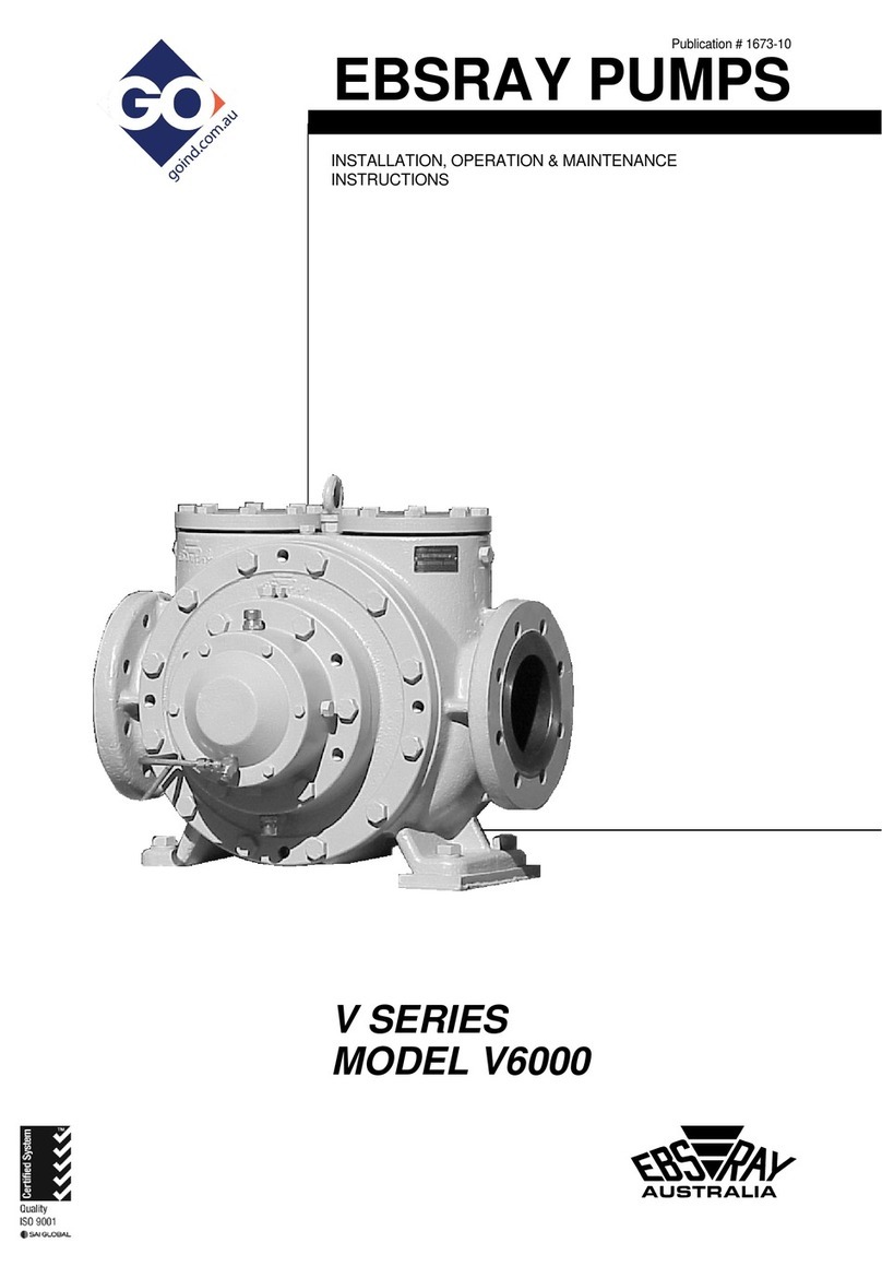
Ebsray V Series Guide

Publication # 2302-13
EBSRAY PUMPS
INSTALLATION, OPERATION &
MAINTENANCE INSTRUCTIONS
V SERIES
MODELS V2000, V3000 & V3010
ROTARY SLIDING VANE PUMPS
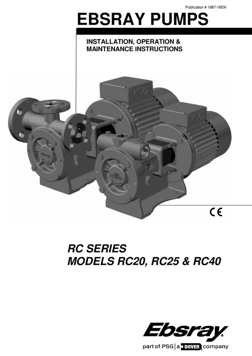
V3000
V3010
V2000

2
CONTENTS
SECTION 1 –GENERAL................................................................................................................................................................3
1.1 INTRODUCTION.....................................................................................................................................................3
1.2 TRANSPORTATION, PACKING & STORAGE........................................................................................................3
1.3 RECEIVING INSPECTION......................................................................................................................................3
1.4 HANDLING..............................................................................................................................................................3
1.5 WARRANTY............................................................................................................................................................3
SECTION 2 –INSTALLATION .......................................................................................................................................................4
2.1 LOCATION ..............................................................................................................................................................4
2.2 FOUNDATIONS.......................................................................................................................................................4
2.3 PUMP PIPING CONNECTIONS..............................................................................................................................4
2.4 STRAINER PROTECTION......................................................................................................................................4
2.5 COUPLING ALIGNMENT........................................................................................................................................4
SECTION 3 –OPERATION ............................................................................................................................................................5
3.1 DESCRIPTION........................................................................................................................................................5
3.2 LUBRICATION.........................................................................................................................................................5
3.3 PRE-STARTUP CHECKLIST ..................................................................................................................................5
3.4 operational checks...................................................................................................................................................5
3.5 PERIODIC INSPECTION ........................................................................................................................................5
SECTION 4 –MAINTENANCE.......................................................................................................................................................5
4.1 PREPARATION FOR DISASSEMBLY ....................................................................................................................5
4.2 DISASSEMBLY .......................................................................................................................................................5
4.2.1 Pressure Relief Valve ......................................................................................................................................5
4.2.2 Pump ...............................................................................................................................................................6
4.3 INSPECTION...........................................................................................................................................................6
4.4 SPARE PARTS........................................................................................................................................................6
4.5 REASSEMBLY - PRELIMINARY.............................................................................................................................6
4.6 REASSEMBLY ........................................................................................................................................................7
4.6.1 Pump ...............................................................................................................................................................7
4.6.2 Pressure Relief Valve.......................................................................................................................................7
SECTION 5 –PARTS DESIGNATION............................................................................................................................................8
SECTION 6 –TROUBLESHOOTING ...........................................................................................................................................10
APPENDIX A –DECLARATION OF CONFORMITY....................................................................................................................11
IMPORTANT NOTES
1. This Publication is TYPICAL ONLY and only relates to the specifications of the minimum equipment required to ensure the
optimum performance, maximum life and trouble-free operation of the Ebsray V2000, V3000 & V3010 Pumps.
2. Products with the mandatory European CE mark affixed indicate conformity to the essential health and safety requirements
via their applicable EU Directives (e.g. ATEX 94/09/EC, Machinery 98/37/EC etc).
As certain specific products/equipment outlined in this Publication are CE marked (meaning the equipment has been
assessed and supplied in conformity to those Directives), STRICT ADHERENCE with ALL the instructions and
recommendations forms an essential part in maintaining the product/equipment’s conformity.
Failure to comply with the instructions and recommendations contained in this Publication may void CE
conformity.
3. This Publication does NOT depict:
a) Ancillary required equipment related to the fabrication, installation and operation of the Pump e.g. miscellaneous flanges,
fittings etc.
b) Required equipment unrelated to the Pumpset e.g. tank fill lines, vapour return lines, emergency shutdown systems etc.
c) The materials and method of fabrication of any required sub-systems.
4. It is the responsibility of the designer, fabricator and the installer of each required sub-system to ensure that:
a) The Ebsray specifications within this Publication and any other relevant Ebsray documents are STRICTLY adhered to.
b) Any variation (including use of equipment deemed "Equivalent") or addition to the Ebsray Specifications, as related to the
Pumpset and Pumping System in general, meet Ebsray's minimum requirements.
c) All design, fabrication and installation of the tank and sub-systems is STRICTLY in accordance with all relevant National,
State and Local Directives, Standards, Codes and Regulations.
5. Ebsray reserves the right to:
a) Withdraw or alter any or all of the Ebsray specifications within this Publication and any other relevant Ebsray documents
without notification.
b) Determine the validity of any Warranty claims for Ebsray equipment based on the proper application of Ebsray supplied
equipment by the way of adherence to the Ebsray specifications within this Publication and any other relevant Ebsray
documents.
EBS-RAY PUMPS Pty. Limited
628 Pittwater Road
Brookvale NSW 2100 Australia
Phone: (+612 9905 0234)
Fax: (+612 9938 3825)
www.ebsraypumps.com.au
or Contact Ebsray Representative:

3
DANGER
Terms used in this publication requiring special attention
1. Non-compliance with requirements under this heading could create circumstances
which may lead to serious personal injury or death or substantial property damage.
2. Non-compliance with requirements under this heading could create circumstances
which may lead to personal injury and/or which may cause damage to the Pumpset
and/or ancillary equipment.
3. Items under this heading draw attention to legal and/or statutory requirements which
control the installation and use of this type of equipment. Non-compliance with these
requirements may create a dangerous situation and/or result in damage to the Pumpset
and ancillary equipment.
4. Items under this heading are to draw attention to assembly procedures, techniques and
methods of operation, etc. which are important to ensure correct installation and
operation of equipment and which, if not followed may result in damage, failure or poor
performance of Pumpset and ancillary equipment.
SECTION 1 –GENERAL
1.1 INTRODUCTION
This publication is intended to assist those involved with the
installation, operation and maintenance of Ebsray Model
V2000, V3000 & V3010 Rotary Sliding Vane Pumps.
Before starting any work, this
publication should be
completely read/reviewed by all
persons involved with the work. If any part of this
publication is unclear, obtain clarification before
proceeding with any work.
If designated forpumping LPG:
-As LPG (Propane and
Butane) is regarded as a flammable liquid, extreme
caution must be taken to ensure total compliance with
all relevant Directives, Standards, Codes and
Regulations is fully understood and exercised in the
installation, operation and maintenance of Ebsray
V2000, V3000 and V3010 pumps.
These instructions are intended to assist correct pump
installation, operation and maintenance requirements.
They are additional to, and do not supersede or
override any applicable statutory, legal or regulatory
requirements.
The design, materials and workmanship incorporated in the
manufacture of Ebsray pumps make them capable of
reliable operation over a long working life. Correct
installation and operation is essential. Service life is
enhanced by periodic inspection and careful maintenance.
Installation and servicing of
this equipment should be
performed by qualified competent personnel in
accordance with relevant Directives, Standards, Codes,
Regulations and site restrictions, in conjunction with
these instructions.
When the equipment supplied utilises components other
than those manufactured by Ebsray e.g. electrical
equipment, switches, fittings, valves, etc reference should
be made to the original manufacturer's data before
installation or servicing is commenced. Failure to observe
these details may void the Warranty.
The pump/pumpset must be
operated within the original
selected design parameters of pumped product (Use
only LPG of internationally accepted (ISO) quality and
specification), speed, flow, pressure, temperature,
voltage and current. Should any change be
contemplated, please confer with Ebsray in order to
verify the suitability of such a change
1.2 TRANSPORTATION, PACKING & STORAGE
Standard domestic packing is suitable for shipment in
covered transports. Pump ports must be sealed to exclude
ingress of condensation, moisture or foreign material. When
received on site the Pumpset must be stored in a dry covered
area.
NOTE: If Pump is not installed and commissioned
immediately, special preservative techniques will be
required. (Refer to Ebsray). e.g. If the Pump is
installed, but not commissioned, low pressure nitrogen
can be used to purge, seal and protect the Pump from
the effects of condensation and atmospheric corrosion.
NEVER allow water or any
corrosive product to enter the
pump (e.g. for hydrostatic testing of pipework). Severe
internal damage may result and will void the Warranty
1.3 RECEIVING INSPECTION
SHORTAGES and/or DAMAGE: On receipt of equipment,
check all items against the dispatch documents and inspect
for damage. Any damage or shortage incurred during transit
should be noted on the packing note and on both your own
and the carrier's copy of the consignment note. A claim
should be made immediately on the transport company. Also
advise Ebsray or their Appointed Representative.
Should a shortage be evident on receipt, notify Ebsray
immediately giving full details and packing note number.
1.4 HANDLING
Do not drop Pump! Care should be taken in
moving/handling Pump/Pumpsets in order to minimise stress
on the internal components.
The Pump/Pumpset should be lifted in such a manner as to
ensure compliance with the relevant lifting codes.
Severe internal Pump damage may result if correct
handling and due care is not taken.
1.5 WARRANTY
1. All Ebsray manufactured pumps and equipment are
warranted as standard for one (1) year against faulty
workmanship and/or materials. Refer to Ebsray PUMPS
'Standard Conditions of Sale and Warranty' publication
for details.
2. Ancillary equipment supplied by Ebsray but manufactured
by others will be in accordance with those manufacturer's
written warranty conditions
WARNING
CAUTION
DANGER
WARNING
ER
WARNING
ER
DANGER
CAUTION
DANGER
DANGER
NOTE:

4
SECTION 2 –INSTALLATION
Installation and removal of this
equipment should be
performed by suitably qualified competent personnel in
accordance with relevant Directives, Standards, Codes,
Regulations and site restrictions - in conjunction with
these instructions.
Never loosen or remove fittings,
flanges, etc. while under
pressure (vapour pressure of
LPG may be very high), always isolate components or
pipework and depressurise prior to work.
2.1 LOCATION
The pumping unit should be placed as close as practicable
to the source of supply keeping within the NPSHr of the
pump. Ensure floor area and headroom allotted are sufficient
for inspection and maintenance. Allow sufficient space and
ventilation for motor cooling requirements. Be sure to allow
for crane or hoist access if required.
2.2 FOUNDATIONS
Baseplate units should be accurately installed. When on a
concrete foundation, ensure that it has been poured on a
solid footing.
2.3 PUMP PIPING CONNECTIONS
NOTE: Never draw piping into place by use of force at
the port connections of the pump.
All piping should be supported independently and line up
accurately with the pump ports.
2.4 STRAINER PROTECTION
The pump suction should always be protected by an efficient
suction strainer of adequate size to accommodate the liquid
viscosity conditions without causing excessive suction
resistance.
2.5 COUPLING ALIGNMENT
To maximise the life of the pump appropriate alignment of the
coupled shafts is a fundamental requirement of any coupling
installation.
NOTE: Coupling types must be selected and installed in
compliance with the relevant Directives, Standards,
Codes, and Regulations dependant on application and
location. (e.g. ATEX compliant –if applicable)
Reference should be made to OEM coupling data for
specific requirements however angular misalignment and
parallel misalignment as shown in Figs 1 & 2 must be
corrected.
If pump was supplied by Ebsray as part of a pumpset unit,
pump and driver have been accurately aligned at factory.
When incorporating these pumps into other equipment,
manufacturers should ensure that coupling alignment is
properly addressed.
To ensure that alignment has been maintained during transit
and installation, alignment MUST BE CHECKED upon final
installation and prior to startup.
Ensure ‘distance between shaft ends’ (DBSE) is correct for
the type of coupling utilised.
ANGULAR MISALIGNMENT as shown in Fig.1 where
shafts are at an angle to one another should be corrected
before parallel misalignment.
Fig 1
PARALLEL MISALIGNMENT as shown in Fig.2 where
shafts are in line angularly and parallel to each other but
are offset can now be corrected.
Adjustment by use of shims under the driver (or pump) will
effectively correct error in the vertical plane.
Movement of one of the ends horizontally will correct error
in the horizontal plane
Fig 2
.
CAUTION
DANGER
DANGER

5
WARNING
ER
SECTION 3 –OPERATION
3.1 DESCRIPTION
The EBSRAY Models V2000, V3000 & V3010 are positive
displacement Sliding Vane Pumps, primarily intended for the
transfer of LPG and other low to medium viscosity liquids. All
models are of identical internal design and construction
however the V3000 is mounted via the top inlet port flange
and has bottom discharge. The V3000 also offers an
alternate 45 inlet port. The V2000 and V3010 are foot
mounted with 90 porting and top discharge. All Models are
available with single or double ended drive shafts. Model
V3010 is available with an aluminium body –application
dependant (not for LPG or Anhydrous Ammonia).
In all models, the Rotor/Shaft assembly rotates within a cam-
form Liner and between two replaceable Wearplates.
Mechanical Seals, located outside the wearplates, isolate the
Drive End and Inspection End Ball Bearings from the
pumpage. These grease packed heavy duty Double Row
Deep Groove Ball Bearings provide positive radial and axial
positioning of the pump rotor. A lip seal is fitted to the Drive
End Cover to minimise the ingress of dust/dirt along the
shaft.
The pump is protected from excessive pressure rise by an
internal pressure relief valve with tamperproof adjustment.
The V2000, V3000 and V3010 Pumps are designed to
provide trouble-free & safe operation and must be operated
in accordance with the following recommendations.
3.2 LUBRICATION
Periodic ball bearing lubrication is required via grease nipples
fitted to the bearing housings at approximately every 500
hours of operation. Ebsray recommends the use of a lithium
complex NLGI Grade 2 grease with an ISO VG220 viscosity
rating.
3.3 PRE-STARTUP CHECKLIST
Do not run Pump dry. Do not
start Pump against closed
Discharge Valve unless external bypass protection is
fitted. Severe internal damage to the Pump will result,
voiding Warranty.
►Lubricate as required.
►Check alignment of couplings.
►Ensure freedom of rotation of shaft.
►Check direction of rotation
►Open inlet and discharge valves
To prevent damage to pump or
system, disengage coupling
before checking direction of rotation.
3.4 OPERATIONAL CHECKS
Inspect pump frequently during the first few hours of
operation for such conditions as excessive heating of ball
bearings, vibration or unusual noises etc.
3.5 PERIODIC INSPECTION
Periodic Inspection of the Pump, Pump System and
Ancillary Equipment is required to maintain safety,
conformity, operational functionality and reliability. Ebsray
recommends a maximum interval of three months or 500
hours operation between routine periodic maintenance
inspections (More frequent inspections may be necessary
dependent upon usage, site conditions, operation etc).
If any abnormal condition is discovered, cease operation of
pump immediately and take action to rectify the problem.
For safe operation, the following items should be included in
the routine periodic inspection:
a. Inspect the Pump for leaks, vibration, abnormal noises,
signs of overheating, discolouration, etc.
b. Inspect Coupling Assembly for signs of wear,
overheating, discolouration, etc.
c. Check Pump differential pressure
SECTION 4 –MAINTENANCE
Prior to any system disassembly
or service, verify that all
requirements of statutory Directives, Standards, Codes
and Regulations, are met and that specific site
requirements etc are satisfied
Some minor maintenance tasks and inspections can be
performed with the pump ‘in line’ so long as complete
isolation, depressurising and purging procedures have been
completed. However for major maintenance it is
recommended that the pump be removed from the
installation
4.1 PREPARATION FOR DISASSEMBLY
1. Obtain the appropriate Work Permit if required.
2. Isolate power supply to motor –if fitted.
3. Isolate pump from liquids in suction and discharge lines,
depressurise and purge out any toxic, flammable,
corrosive or air hardening liquids (if present).
4. Disconnect porting connections.
5. Remove pump from installation.
4.2 DISASSEMBLY
Refer to the Parts Designation drawings in Section 5
4.2.1 Pressure Relief Valve
1. Remove flush plug from valve cover.
2. Using a 6mm allen wrench, turn the adjusting screw
clockwise to reduce spring tension.
3. Remove valve cover and O-Ring together with spring
cap, spring and valve.
4. Remove spring cap from valve cover and remove O-Ring
from spring cap.
WARNING
ER
CAUTION
DANGER

6
4.2.2 Pump
1. Remove dust caps from drive end and inspection end
bearing housings.
2. Remove lockwashers and locknuts from both inspection
end and drive end of shaft.
3. Remove both bearing housings. (To remove bearing
housing, screw two of the bearing housing setscrews into
the tapped holes provided in the bearing housing. Evenly
tighten the setscrews to withdraw the bearing housing.)
Take care not to damage the mechanical seal faces.
4. Press out the ball bearings from the bearing housings.
5. Remove the bearing dampening O-Rings from the shaft
then carefully remove the mechanical seal components
from both the bearing housings and from the rotor/shaft
assembly.
6. Remove body covers and wearplates (To remove body
cover, screw four of the bearing housing setscrews into
the tapped extraction holes provided in the body cover.
Evenly tighten the setscrews to withdraw the body cover.)
7. Withdraw the rotor/shaft/vane assembly from the body
taking care to support the vanes as the assembly is
withdrawn.
8. Remove vanes and pushrods from the rotor (note the
orientation of the vanes relative to the direction of
rotation)
9. Remove liner from body (note the orientation of the liner
relative to the inlet and discharge ports of the body.
10.Remove grease nipples and pressure release plugs from
the bearing housings.
11.Remove oil seal from drive end dust cap.
4.3 INSPECTION
NOTE: Optimum performance is achieved by
maintaining the pump within the following
guidelines.
Adequate performance may still be achieved
dependent on application parameters.
1. Inspect rotor/shaft assembly and liner. If damage or
excessive wear is evident, it is recommended to replace
both components. Scoring in the seal zones of the liner is
detrimental to optimum performance.
NB: The rotor is permanently attached to the shaft.
2. Inspect both mechanical seals. Replace mechanical seal
assembly if components are worn or damaged
3. Inspect vane pushrods for wear, damage and
straightness. Replace the pushrods if they show signs of
physical damage, wear or distortion e.g. mushroomed,
rounded or tapered ends, scoring on flanks, bending,
etc.
4. Inspect vanes for wear or damage. Replace if damaged
or excessive wear is evident. Check for scoring on vane
tips.
Recommended Minimum
Worn Vane Sizes
Vane
Length
Vane
Height
V2000
74.62mm
27.00mm
V3000
89.62mm
28.00mm
V3010
89.62mm
28.00mm
5. Inspect pressure relief valve assembly and components
for wear or damage. Replace or refurbish as required.
6. It is recommended that all O-Rings and lip seals be
replaced at every overhaul.
7. Inspect both ball bearings for wear. It is recommended
on major overhauls that ball bearings be replaced.
8. Ensure pressure relief ducts in bearing housings are not
obstructed.
4.4 SPARE PARTS
1. When ordering spare parts, to ensure a minimum of
delay and correct replacement to original specification,
ALWAYS quote the pump Serial Number located on the
nameplate of the pump.
2. Advise the name, Cat # and quantity required. Refer
Section 5 –Parts Designation.
3. Advise complete delivery instructions, transportation,
etc.
NOTE: Substitute or so-called ‘equivalent’ item/spare
parts are not recommended for use.
Compliance, safe operation and pump performance
may be severely compromised if incorrect or substitute
spare parts –including Fasteners, O-Rings, Ball
Bearings, etc –are used.
Only use genuine Ebsray spare parts.
4.5 REASSEMBLY - PRELIMINARY
1. Ensure all parts are clean and deburred before
assembly.
At all times when handling and
installing mechanical seals,
care must be taken to ensure lapped faces and seats
are not damaged. Particular attention must be given to
carbon seats to prevent marking or chipping.
2. Lubricate all O-Rings and lapped faces of mechanical
seals with a good quality, compatible, detergent-free
light oil before assembly.
3. Pack Ball Bearings with a good quality, suitable grease.
4. Ensure correct orientation of components relative to
pump rotation/handing .
CAUTION
DANGER
Ball Bearing Replacement interval should not exceed
V2000 10,000 operational hours
V3000 5,000 operational hours
V3010 5,000 operational hours

7
4.6 REASSEMBLY
(Refer Section 5 –Parts Designation)
4.6.1 Pump
1. Fit liner to body ensuring correct orientation. (Liner is
located using the key which is pinned to the body, the
word "OUT" is cast into the liner and this must be
towards the discharge port area..
2. Fit one wearplate to one end of the body ensuring body
key locates in slot in wearplate. Fit body cover with new
O-Ring to secure wearplate.
3. Assemble three lower vanes in the rotor and whilst
cradling these to prevent them dropping out, insert the
three pushrods into the rotor.
NB: Vanes must be correctly oriented i.e. the rounded ends
of the vanes contact the liner and the slots in the face of
the vanes must lead the direction of rotation.
4. Insert the rotor/shaft/vane/pushrod assembly into the
body and then insert the other three vanes ensuring
correct orientation.
5. Fit wearplate to other end of body, ensuring body key
locates in slot in wearplate.
6. Fit body cover with new O-Ring.
7. Fit rotating components of mechanical seal assemblies
to each end of shaft.
NB: Ensure mechanical seal components are clean prior to
assembly, lubricate before fitting and ensure that O-Rings
locate correctly on shaft and that slots in seal assembly
locate over drivepins in shaft.
8. Fit O-Rings to stationary seal faces, lubricate and fit
stationary seal faces to bearing housings taking care to
ensure that location pins locate in holes provided in
bearing housings. Place seal failure O-Rings in bearing
housings inside stationary seal faces.
9. Fit O-Rings to bearing housings.
10. Carefully fit bearing housings over shaft and fasten to
body covers.
NB: When fitting bearing housings, ensure that seal failure
O-Rings are not dislodged. Seal failure O-Rings must
remain captive between bearing housing and stationary
seal face.
11. Fit bearing dampening O-Ring to each end of shaft and
slide along shaft until seated in groove.
12. Fit ball bearings over shaft and into bearing housings.
13. Fit lockwashers and locknuts to shaft.
NB: Do not tighten locknuts at this stage.
Lockwashers must not be
reused as bending the tabs
more than once may cause fatigue which could result in
failure and/or major pump damage. Only reassemble
with new lockwashers of the correct thickness (Refer
parts list)
TO SET AXIAL CLEARANCES IN PUMP:
14. While rotating shaft by hand using a suitable handle,
tighten inspection end locknut until rotor/shaft assembly
locks. At this point, the end of the rotor should be hard
against the wearplate.
15. Back off the inspection end locknut 0.5 (one half) tab –
(see diagram) then, if necessary back it off slightly
further (only as far as required to align a locking tab).
Lock in this position with tab of lockwasher
Fig 3
16. While turning shaft, tighten drive end locknut until an
increase in drag is felt (pre-loading), indicating that ball
bearings are tightly clamped.
17. Back off drive end locknut just enough to allow free pump
rotation while maintaining some pre-loading on drive end
ball bearing. Then if necessary back it off slightly further
(only as far as required to align a locking tab) Lock in
this position with tab of lockwasher.
18. Fit dust covers to both ends of pump with new seal in
drive end dust cover.
19. Fit grease nipples and pressure release plugs to the
bearing housings.
4.6.2 Pressure Relief Valve
1. Screw adjusting screw fully into spring cap and fit O-
Rings to spring cap and valve cover.
2. Lubricate bore of valve cover and insert spring cap
partially into valve cover.
3. Fit valve, spring and valve cover assembly to body and
fasten into position.
4. Use a 6mm allen wrench to adjust pressure relief valve
setting.
NOTE: Clockwise movement of the adjusting screw
reduces spring tension thus reducing differential
bypass pressure. Anticlockwise movement of the
adjusting screw increases spring pressure thus
increasing differential bypass pressure.
Never set differential bypass pressure above 1050 kpa
(150psi)
5. After adjustment, replace flush plug in valve cover.
Pump Fastener Torque settings: V2000 V3000/V3010 V3010
Body Material DI DI AL
Body Cover to Body 77Nm 77Nm 77Nm
Valve Cover to Body 44Nm 44Nm 30Nm
Brg Housing to Body Cover 44Nm 44Nm 44Nm
Dust Cap to Brg Housing 2Nm 2Nm 2Nm
Adapter Flange to Body 44Nm 44Nm 30Nm
Suction Flange (CL 300) Dependent on Gasket
(DI=Ductile Iron, AL=Aluminium))
WARNING
ER

SECTION 5 –PARTS DESIGNATION
MODELS: V2000, V3000 and V3010 Rotary Sliding Vane pump.
Cat#
Description
Qty
Cat#
Description
Qty
100
Body
1
410
Valve Seat (for aluminium body only)
1
101
Liner
1
415
Spring - Bypass Valve
1
102
Rotor/Shaft assembly
1
416
Spring Cap
1
107
Wearplate
2
500
Mechanical Seal Assembly
2
111
Vane
6
512
Oil Seal
1
115
Vane Pushrod
3
515
O-Ring - Body Cover
2
116/117
Body Key Assembly
1
516
O-Ring - Valve Cover
1
200
Bearing Housing
2
517
O-Ring - Spring Cap
1
201
Body Cover
2
522
O-Ring - Bearing Housing
2
202
Dust Cap - Drive End
1
523
O-Ring - Seal Failure
2
203
Gasket –Dust Cap
2
617
Plug
2
204
Double Row Deep Groove Ball Bearing
2
617A
Plug
1
207
Locknut
2
618
Coupling Key
1
208
Lockwasher (1.8mm thickness)
2
620
Bolt - Body Cover
16
212
Setscrew –Dust Cap
8
621
Bolt - Bearing Housing
8
216
O-Ring - Bearing dampening
2
622
Bolt –Valve Cover
4
302 or
317
Dust Cap - Inspection End or
Shaft Cap –Inspection End
1
640
Dowel
2
400
Valve Cover
1
650
Grease Nipple
2
401
Adjusting Screw - Bypass Valve
1
651
Grease Pressure Relief
4
409
Valve
1
Adaptor Flange Options
770K
Adaptor Flange Kit (Straight)
1
790K
Adaptor Flange Kit (Elbow)
#761 O-Ring - Adaptor Flange
1
#761 O-Ring - Adaptor Flange
1
#765 Bolt - Adaptor Flange
4
#765 Bolt - Adaptor Flange
4
#770 Adaptor Flange - 2" NPT or
Adaptor Flange - 2 1/2" NPT
1
#790 Adaptor Flange - 2" NPT
Elbow
1
604K
Blanking Flange Kit
#761 O-Ring - Adaptor Flange
1
#765 Bolt - Adaptor Flange
4
#604 Blanking Flange
1
Adaptor Flange Options
Model
Inlet
Alt Inlet
Discharge
Note
V2000
2-1/2” NPT Adp Flg Kit or
2” NPT Adp Flg Kit
NA
2” NPTAdp Flg Kit or
2-1/2” NPT Adp Flg Kit
V2000 Only
V3000
3” CL 300
2-1/2” NPT Adp Flg Kit or
2” NPT Adp Flg Kit or
2” NPT Elbow Kit
2” NPT Elbow Kit or
2” NPT Adp Flg Kit or
2-1/2” NPT Adp Flg Kit
Interchangeable with
V3010
V3010
2-1/2” NPT Adp Flg Kit or
2” NPT Adp Flg Kit or
2” NPT Elbow Kit
NA
2” NPT Adp Flg Kit or
2-1/2” NPT Adp Flg Kit or
2” NPT Elbow Kit
Interchangeable with
V3000

9

10
SECTION 6 –TROUBLESHOOTING
Symptom
Possible
Problem
Possible Cause
Remedy
No Liquid
Delivery
Pump not operating
No power to drive shaft
Check driver
Coupling damaged or disengaged
Repair/replace coupling
Pump will not turn –
locked up
Foreign matter in pump
Clean out pump –check strainer in
suction line.
Vanes/Pushrods broken
Clean pump and replace
Vanes/Pushrods
Ball Bearings seized
Replace Ball Bearings.
With pump operating
Inlet/Discharge valves closed
Open valves
No liquid in supply tank
Fill supply tank
Incorrect direction of rotation
Ensure correct direction of rotation
Suction filter/strainer blocked or
leaking air
Clean filter/strainer and/or eliminate air
leaks
High static discharge pressure
Review system design
Inadequate NPSHa
Increase NPSHa
Pump vapour locked
Clear vapour to enable pump to prime
Reduced
Output
Pump speed too slow
Incorrect driver speed
Replace/adjust driver
Faulty driver
Replace/repair as required
High differential
pressure
Restriction in discharge piping or
pipe/hose too small.
Remove restriction and/or replace with
adequate size pipe/hose
Restriction in inlet line
Strainer blocked
Clean/clear strainer
Inlet pipe too small or too long
Modify piping
Foreign object in suction line
Remove restriction
Incorrectly set external
Bypass Valve or
internal Pressure
Relief Valve
Valve pressure setting too low
Adjust pressure setting but do NOT
exceed system design pressure or driver
capability
Vanes jamming
Foreign matter in pump or damaged
vanes
Clean out pump and/or replace vanes
Pump parts worn
End of service life or adverse
pumping conditions
Recondition pump
Excessive
Power
Consumpti
on
Obstruction is
discharge line
Foreign matter in discharge line
Clean or clear out discharge line
Collapsed or kinked discharge hose
Replace hose or remove kinks
Operating outside duty
point
Pressure, Viscosity, Temperature
and/or Speed not as specified
Correct as required
Rotating parts binding
Foreign matter jamming parts or
parts worn
Disassemble, inspect and rectify
Misalignment between
pump and driver
Pump and/or driver moved
Check and realign as required.
Ball Bearings worn
End of service life or adverse
pumping conditions
Replace Ball Bearings
Pump is
Noisy
Cavitation
Insufficient NPSH available
Increase NPSHa
Air leakage in suction line
Remove air leakage
Pump running dry
No liquid in supply tank
Fill supply tank
Closed inlet line valve
Open inlet line valve
Rotating parts binding
Foreign matter jamming parts or
parts worn
Disassemble, inspect and rectify
Ball bearings worn
End of service life or adverse
pumping conditions
Replace ball bearings
Pump speed too fast
Incorrect drive speed
Reduce drive speed

11
Publication No 2490-08
EC DECLARATION OF CONFORMITY
Item
Content based upon Annex X of ATEX Directive 94/9/EC
Manufacturer
Ebsray Pumps Pty Ltd
Address
628 Pittwater Road Brookvale NSW 2100 Australia
Manufacturer’s Declaration
We, Ebsray Pumps Pty Ltd declare that the following equipment :
Description of Equipment
Ebsray V Series Sliding Vane bareshaft Pump ;
Model / Type :
V15 (all Types) except Liquefied Gases
V20 (all Types)
V25 (all Types) except Liquefied Gases
V2000 (all Types)
V3000 (all Types)
V3010 (all Types)
V30 (all Types)
V40 (all Types)
V6000 (all Types)
The above Models are positive displacement sliding vane Pumps for liquid
transfer applications. These Models / Types must only be applied in systems
designed for that Model/Type’s intended use.
The above Models bear the following marking (where applicable) :
II 2 G c T4
Declaration of compliance
Is designed and manufactured in compliance with the following applicable
Directives :
Applicable Directives
evaluated by Manufacturer
- not checked by Notified
Body
First applicable Directive
Individual declaration of
compliance
ATEX Directive 94/9/EC - by application of the following Standards :
EN 1127-1 (2007)
EN 13463-1 (2001)
EN 13463-5 (2003)
Second applicable Directive
Pressure Equipment Directive (PED) 97/23/EC - but excluded under Article 3.10
Third applicable Directive
Machinery Directive (MD) 98/37/EC –by application of the following Standards :
EN ISO 12100-1 (2003)
EN ISO 12100-2 (2003)
EN 809 (1998)
Manufacturer’s own
warning
Subject to the use for which the product(s) were designed and/or installed in
accordance with the relevant Standards and Codes –all in conjunction with the
Manufacturer’s own Installation and Operating Instructions and
recommendations
Final declaration
We, the undersigned, hereby declare that the product(s) specified conform to the
listed Directive(s) and Standard(s)
Signatory of person legally
responsible
Ebsray Pumps Pty Ltd
W.A.Ebsary - Managing Director
Place / Date
Brookvale, Australia / 22 April 2008
Symptom
Possible
Problem
Possible Cause
Remedy
Leakage
from
Pump
Mechanical Seal
leakage
Seals incorrectly installed
Inspect seal assembly, replace if
necessary and install correctly
Excessive dry running of pump
Ensure liquid-state operation of pump
Seal faces cracked, scratched, pitted
or dirty
Inspect and replace seal assembly if
required
O-Rings nicked, cut or twisted
Replace as required
O-Rings not compatible with
pumpage
Replace with O-Rings of a compatible
material
Worn or damaged shaft in seal zone
Replace rotor on shaft assembly
Misalignment causing excessive
shaft distortion
Check and realign as required.
Excess system pressure
Check and adjust to requirements
Casing leakage
O-Rings failed
Replace as required
Fasteners not tight
Tighten to required torque setting
Thermal expansion of product when
locked between valves either side of
pump
Remove hydraulic lock potential
Excessive static pressure
Eliminate excessive static pressure
APPENDIX A –DECLARATION OF CONFORMITY

12
NOTES
Other manuals for V Series
2
This manual suits for next models
3
Table of contents
Other Ebsray Water Pump manuals
Popular Water Pump manuals by other brands

K2 Pumps
K2 Pumps WPS05004K owner's manual

Cheonsei
Cheonsei Kempion PKD Series instruction manual

Calpeda
Calpeda e-idos E-MPSM operating instructions

Far Tools
Far Tools WP 400D manual

HALE
HALE Silencer APS Series Installation, Operation and Service Maintenance Manual

Wayne
Wayne CDUCAP1000 Warranty & service parts sheet

SPIDO
SPIDO 002074-REV01 operating instructions

Stanley
Stanley SXUP1000XWE manual

Liberty Pumps
Liberty Pumps SPAC-237 installation manual

Grundfos
Grundfos DME 60 Installation and operating instructions

Waterous
Waterous TC20 Series OVERHAUL INSTRUCTIONS

Richter
Richter MNK-B Series Installation and operating manual