6
3.1.6 Bypass Valve
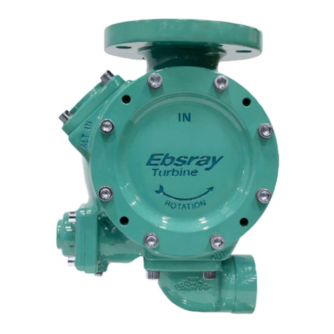
Bypass Valve (Ebsray Model RV18-VRS or CBS)
(Refer Appendix A - P & ID for details) is installed on
the pump discharge side and returns back-to-tank. It
may be mounted directly on the 'spare' discharge port or
in the discharge pipe (before any isolation valve). This
Bypass Valve is primarily for control of differential
pressure. (NOTE: Variation in tank vapour pressure has
a direct effect upon discharge pressure whilst constant
differential pressure is maintained).
If VRS option is used (Refer Appendix A - P & ID for
details), a critical function performed by this unique
Bypass Valve is its rapid vapour handling capability
during the pump start-up/priming cycle. (Also refer to
Ebsray RV18 Bypass Valve Brochure for details and
functionality.)
Ensure correct orientation i.e. flow is 'IN' from pump
discharge line and 'OUT' returns to tank.
NOTE: The Bypass Valve’s return-to-tank pipeline
MUST NOT have any restrictions which could
adversely affect or limit the vapour clearing
function during pump priming.
An Excess Flow Valve or other 'normally open' tank
valve is recommended/ preferred.
Flow of LPG during bypassing should return to Storage
Tank vapour space.
SECTION 4 – OPERATION
4.1 DESCRIPTION
1. Pump
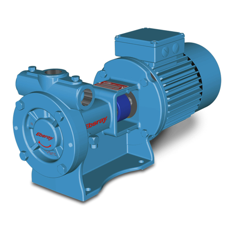
The Ebsray RC Series pumps are designed for ultra
quiet operation pumping LPG of Internationally
accepted (ISO) quality and specification.
The Pump meets the requirements of Australian,
European ATEX and other International Standards
and Codes for use in potentially explosive
atmospheres.
2. Motor
Certified explosion protected IEC frame 90 or 100 B5
Flange Mount 50Hz 2880 RPM or 60Hz 3500 RPM
electric motors fit directly onto RC Series pumps.
The RC20 uses 1.5 or 2.2kW and the RC25 uses 2.2
or 3.0kW Motors which can be either supplied by
EBSRAY or customer supplied. Motor must be wired
with a correctly sized IEC class 10A thermal overload
relay, and set to no more than the FLA of the motor.
Ensure motor conformity with all necessary Directives,
Standards, Codes, Regulations and site requirements.
3. Coupling
Non-Sparking design (e.g. “polygear” type) – sized to
suit duty. Supplied by Ebsray or customer supplied.
4.2 LUBRICATION
The Ball Bearings for the RC Series pumps are
grease lubricated and 'sealed-for-life' design.
No 'in service' lubrication is required on EBSRAY's
RC Series Pumps.
For motor, refer to specific motor manufacturer's
recommendations.
4.3 PRE-STARTUP CHECKLIST
Refer to pre-start inspection checklist (Appendix B)
Do not run Pumpset dry.
Do not start Pump against
e. Severe internal damage
to the Pumpset will result, voiding Warranty.
closed Discharge Valv
4.4 STARTUP PROCEDURE
Fill in the ‘Pump Run Log’ provided in Appendix C
.
2. pressure gauge. the
6 Start Pumpset.
1 Ensure all conditions described in Pre-Startup
Checklist have been met.
Check reading on discharge
Record product vapour pressure in
commissioning section of the Pump Run Log.
3. Back-off Bypass Valve Adjusting Screw (screw to
maximum 'out' position).
4. Verify all site conditions and statutory requirements
have been met.
5. Briefly activate power (i.e. 'jog' motor) to verify
correct pump rotation. (Cast arrow on cover)
If any aspect of the
pumpset or pumping
system does not function properly, immediately
turn the pump 'off' and rectify the problem before
re-starting.
7. After startup, pump should immediately begin to
build differential pressure. If pump does not
prime immediately, switch off to determine reason
and rectify before re-starting.
8. After startup, initially ensure that liquid is flowing
through Bypass Valve. This should be detectable
by listening or feeling the Bypass Valve.
Screw 'in' the Bypass Valve Adjusting Screw until
the required system differential pressure is
achieved.
Record discharge pressure in the commissioning
section of the Pump Run Log.
9. Check that motor current is below FLA rating.
Record motor current readings in the
commissioning section of the Pump Run Log.
NOTE: During this procedure, or at any time,
motor current must not exceed FLA rating of
motor.
10. Stop pump, restart and check for consistent results.
11. Record discharge pressure and current readings in
the commissioning section of the Pump Run Log.
12. The Pumpset is now ready for normal operation.
13. After final Bypass Valve adjustment, tighten
adjusting screw locknut and seal for security.
14. The startup procedure is now complete.
15. Inspect Pumpset/pumping system frequently during
the first few hours of operation then periodically
thereafter (see Section 4.5 for frequency).
Record observations from these inspections in the
Pump Run Log.


