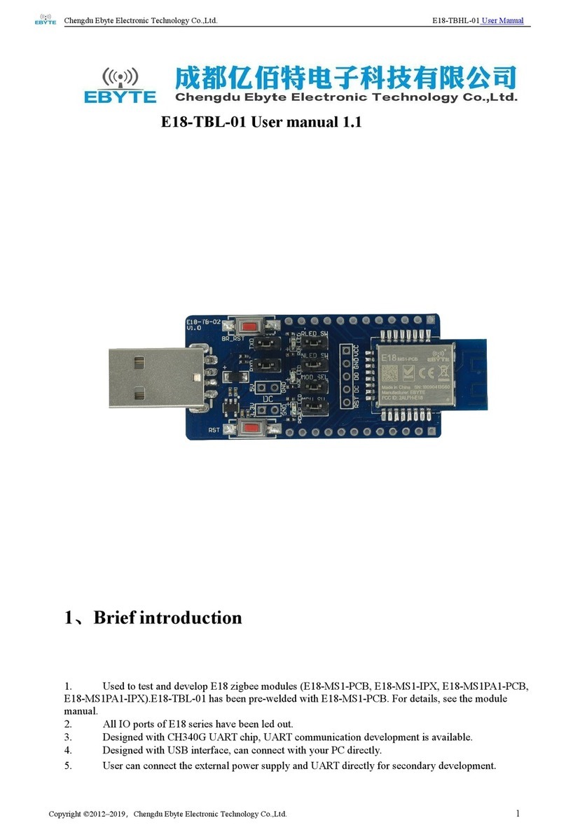
Ebyte ECAN-W01 User manual

Chengdu Ebyte Electronic Technology Co., Ltd ECAN-W01 User Manual
Copyright©2012–2022, Chengdu Ebyte Electronic Technology Co.,Ltd
CONTENT
1. Product Introduction ...............................................................................................................................................3
1.1. Product introduction ...............................................................................................................................3
1.2. Functional features .................................................................................................................................3
2. Quick Get Start .......................................................................................................................................................4
3. Technical Indicators ............................................................................................................................................... 6
3.1. General specifications ............................................................................................................................6
3.2. Mechanical dimension drawing and pin definition ............................................................................... 7
4. Product Function Introduction ............................................................................................................................... 9
4.1. WiFi function ......................................................................................................................................... 9
4.1.1. AP mode .........................................................................................................................................9
4.1.2. STA mode .......................................................................................................................................9
4.2. Basic function ........................................................................................................................................ 9
4.2.1. SOCKET function ..........................................................................................................................9
4.2.2. TCP Client Function ...................................................................................................................... 9
4.2.3. TCP Server Functions .................................................................................................................. 10
4.2.4. UDP Client Functions .................................................................................................................. 10
4.2.5. UDP Server Features ....................................................................................................................10
4.2.6. CAN function ...............................................................................................................................11
4.2.7. CAN protocol conversion format ................................................................................................ 14
4.3. Features ................................................................................................................................................ 15
4.3.1. CAN filtering ............................................................................................................................... 15
4.3.2. Custom baud rate ......................................................................................................................... 16
4.3.3. Modify baud rate online ...............................................................................................................17
4.3.4. Heartbeat function ........................................................................................................................18
4.3.5. Registration package function ..................................................................................................... 18
4.3.6. Timeout restart function ...............................................................................................................19
4.4. Support DHCP and domain name resolution .......................................................................................19
4.4.1. DHCP ........................................................................................................................................... 19
4.4.2. DNS (Domain Name Resolution) ................................................................................................19
4.5. Disconnection reconnection .................................................................................................................20
4.6. Network interface upgrade ...................................................................................................................20
4.7. Restore factory settings ........................................................................................................................22
5. Important statements ............................................................................................................................................ 22
6. Revision History ...................................................................................................................................................23
7. About us ............................................................................................................................................................... 23
Chengdu Ebyte Electronic Technology Co., Ltd ECAN-W01 User Manual
Copyright©2012–2022, Chengdu Ebyte Electronic Technology Co.,Ltd
1. Product Introduction
1.1. Product introduction
ECAN-W01 is a high-performance industrial WIFI and CAN
bus data conversion equipment developed by EBT. It integrates
two CAN bus interfaces, one EtherNet interface and one WiFi
interface internally, which can easily complete the
interworking of CAN bus network and WiFi network.
ECAN-W01 has a built-in 120 ohm resistor, which can be
enabled by dialing; Support the operation within the
temperature range of - 40 ℃~85 ℃. It has a 10M Ethernet
interface. Customers can use the network cable to connect the
PC end and enter the configuration software to configure the
device parameters; The device WiFi network has two modes: AP and STA, which can quickly establish
or access the WiFi network; High protection of CAN interface, increased isolation; 2-channel CAN
port communication supports fixed common CAN baud rate and user-defined CAN baud rate, with the
highest baud rate of 1Mbps; At the same time, the device has multiple working modes such as TCP
Server, TCP Client, UDP, etc.
1.2. Functional features
Integrated 2-way CAN bus interface, using plug-in terminal wiring mode;
Support CAN2.0A and CAN2.0B frame formats and conform to ISO/DIS 11898 specification;
CAN bus communication baud rate between 5Kbps and 1Mbps can be programmed arbitrarily;
Dual CAN transceiver supports dual server, and each channel supports up to 4 links;
Integrated 2.4G WiFi interface, conforming to IEEE802.11a/b/g standard;
Support WiFi AP/STA mode, and access up to 5 STA devices in AP mode;
The CAN bus interface adopts electrical isolation, and the isolation module insulation voltage:
DC 2500V;
Maximum transmission data flow: 8000 frames/second; Maximum received data flow: 14000
frames/second;
Support registration package and heartbeat package;
Support DHCP and DNS;
Support offline restart/timeout restart;
Support upper computer configuration;
Support online modification of baud rate;
Including 120 ohm resistance;
Built in watchdog;

Chengdu Ebyte Electronic Technology Co., Ltd ECAN-W01 User Manual
Copyright©2012–2022, Chengdu Ebyte Electronic Technology Co.,Ltd
Network interface upgrading function;
Working temperature range: - 40 ℃~+85 ℃.
2. Quick Get Start
You need quasi ECAN-W01 * 1, power adapter * 1, network cable * 1, 2.4GWiFi antenna * 1, CAN
analyzer * 1;
1、 The factory default of the device is AP mode, the SSID is ECAN-W01-XX, and the password is
12345678. After the device is powered on, search the device WiFi through the PC, as shown in
the following figure:
Click Connect to connect to the device's WiFi
2、 Open the network debugging assistant of the computer, set it as TCP Client, set the remote
host IP to 192.168.4.101, and set the remote host port number to 8881.
3、 Connect CAN1 of ECAN-W01 to CAN resolver. When ECAN-W01 is connected to CAN bus, just connect
CAN_ H connected to CAN_ H,CAN_ L connected to CAN_ L is enough. (Note that the default CAN
baud rate is 100K)
4、 The network assistant can be used to realize the communication between devices and peripherals.

Chengdu Ebyte Electronic Technology Co., Ltd ECAN-W01 User Manual
Copyright©2012–2022, Chengdu Ebyte Electronic Technology Co., Ltd
3. Technical Indicators
3.1. General specifications
Serial No
Project
Specifications
1
supply voltage
8V~28VDC, over 28V may burn out, 12V or 24V power supply
is recommended
2
Mesh port
specification
Standard RJ45, supporting 10Mbps
3
WiFi
specifications
IEEE802.11a/b/g standard
4
Network Protocol
IP、 TCP/UDP、WiFi
5
Simple transparent
transmission mode
TCP Server、TCP Client、UDP Server、UDP Client
6
TCP Server
Connection
A maximum of four TCP connections are supported in a
single channel
7
IP acquisition
method
Static IP, DHCP
8
Domain name
resolution
support
9
User Configuration
Upper computer configuration
10
working
temperature
-40~+85 ℃, industrial grade
11
Operating humidity
10%~90%, relative humidity, non condensing
12
Size
See dimension drawing
13
Average weight
120g
14
Storage
temperature
-40~+85 ℃, industrial grade

Chengdu Ebyte Electronic Technology Co., Ltd ECAN-W01 User Manual
Copyright©2012–2022, Chengdu Ebyte Electronic Technology Co.,Ltd
Serial No
Identifica
tion name
Function description
1
ANT
WiFi antenna SMA interface
2
ETHERNET
Ethernet interface, standard RJ45 interface, connected
to PC
3
V+
Power positive interface, 5.08 phoenix head, (default
8-28V), 12V/24V recommended
V-
Power supply cathode interface 5.08 Phoenix head
4
Reload
Reload button, press and hold for more than 5s to restore
the factory
5
CAN2_ H
CAN2 channel bus high, 5.08 phoenix head
CAN2_ G
CAN2 channel bus ground, 5.08 phoenix head
CAN2_ L
CAN2 channel bus low, 5.08 phoenix head
6
Dial RES1
CAN1 channel 120 ohm resistance dial switch
Dial RES2
CAN2 channel 120 ohm resistance dial switch
7
CAN1_ H
CAN1 channel bus high, 5.08 phoenix head
CAN1_ G
CAN1 channel bus ground, 5.08 Phoenix head
CAN1_ L
CAN1 channel bus low, 5.08 phoenix head
8
SYS
Power indicator (red), network access (red flashing)
9
CAN1/ERR
CAN1 data light (green), data error light (red)
10
CAN2/ERR
CAN2 data light (green), data error light (red)

Chengdu Ebyte Electronic Technology Co., Ltd ECAN-W01 User Manual
Copyright©2012–2022, Chengdu Ebyte Electronic Technology Co.,Ltd
4. Product Function Introduction
4.1. WiFi function
4.1.1. AP mode
Access Point is referred to as AP mode for short. It is similar to a router, allowing wireless
devices to connect and establishing TCP/IP based server, client, and UDP communications. In this
mode, four stations can be connected, and each TCP server supports up to four TCP sockets. By
default, the device is in AP mode. The SSID is ECAN-W01-XX-XX-XX-XX (followed by the device MAC
address). The default secret key is 12345678.
4.1.2. STA mode
Station mode is called STA for short. The device in this role does not provide connection,
but can only connect to Access Points or routers. The device in the Station role supports TCP
server, TCP client, and UDP; Under the TCP server, each channel supports a maximum of four sockets.
When the device switches from other working roles to STA mode, the device can enable DHCP to obtain
IP addresses, and automatically configure the gateway, subnet mask, and DNS domain name server.
It can also set a static IP address for networking.
4.2. Basic function
→ Ethernet part
4.2.1. SOCKET function
ECAN-W01 can establish two sockets, namely Socket A1 and Socket B1. Both of them support TCP
Client, TCP Server, UDP Client and UDP Server.
Two sockets run simultaneously. It can be connected to different networks at the same time
for data transmission.
When the device SOCKET is a TCP Server, each SOCKET can access up to four links at the same
time, and two SOCKET can have up to eight links.
4.2.2. TCP Client Function
(1) TCP Client provides client connection for TCP network service. Initiate a connection
request to the server and establish a connection to realize the interaction between CAN data and
server data. According to the relevant provisions of the TCP protocol, the TCP client has the
difference between connection and disconnection to ensure reliable data exchange. Usually used
for data interaction between devices and servers, it is the most commonly used networking

Chengdu Ebyte Electronic Technology Co., Ltd ECAN-W01 User Manual
Copyright©2012–2022, Chengdu Ebyte Electronic Technology Co.,Ltd
communication mode.
(2) When ECAN-W01 attempts to connect to the server in TCP Client mode and the local port
is 0, it initiates a connection with a random port each time.
(3) In the same LAN, if ECAN-W01 is set as a static IP, please keep the IP and gateway of
ECAN-W01 in the same network segment, and set the gateway IP correctly, otherwise normal
communication will not be possible.
4.2.3. TCP Server Functions
(1) TCP Server is the TCP server. In TCP Server mode, ECAN-W01 listens to the local port,
accepts and establishes a connection for data communication when a connection request is sent,
and sends the data to all client devices that establish a connection with ECAN-W01 at the same
time after receiving the data.
(2) It is usually used for communication with TCP clients in the LAN. It is suitable for
scenarios where there is no server in the LAN and multiple computers or mobile phones request
data from the server. Like TCP Client, it has the difference between connection and disconnection
to ensure reliable data exchange.
(3) When ECAN-W01 is used as a TCP server, up to 8 clients can be supported in a dual socket,
and up to 4 clients can be supported in a single socket. The local port number is a fixed value
and cannot be set to 0.
4.2.4. UDP Client Functions
(1) UDP Client is a connectionless transmission protocol that provides simple and unreliable
transaction oriented information transmission services. Without connection establishment and
disconnection, you only need to specify an IP and port to send data to the other party. It is
usually used in data transmission scenarios where there is no requirement for packet loss rate,
the data packet is small, the transmission frequency is fast, and the data is to be transmitted
to the specified IP.
(2) In UDP Client mode, ECAN-W01 will only communicate with the target port of the target
IP. If the data does not come from this channel, the data will not be received by ECAN-W01.
(3) In UDP Client mode, if the target address is set to 255.255.255.255, the effect of UDP
full network segment broadcast can be achieved, and broadcast data can also be received. ECAN-W01
module supports broadcast within the network segment, such as the broadcast mode of xxx. xxx.
xxx. 255.
4.2.5. UDP Server Features
(1) UDP Server does not verify the source IP address on the basis of ordinary UDP. After receiving
a UDP packet, it changes the target IP address to the data source IP address and port number.
When sending data, it sends the IP address and port number of the latest communication.

Chengdu Ebyte Electronic Technology Co., Ltd ECAN-W01 User Manual
Copyright©2012–2022, Chengdu Ebyte Electronic Technology Co.,Ltd
(2) This mode is usually used in data transmission scenarios where multiple network devices
need to communicate with modules and do not want to use TCP due to high speed and frequency.
Note: UDP Server cannot actively send data. Only after receiving the data can it send the
data to the IP and port that has recently conducted data interaction.
→ CAN part
4.2.6. CAN function
category
name
default
explain
CAN
configura
tion
CAN baud
rate
100K
There are 10 options from 5K to 1000K. You can
also fill in any baud rate value yourself.
CAN operating
mode
normal
Normal: CAN port can normally respond to
received CAN frame;
Number of
subcontractin
g frames
50
The value that can be filled in is 1~50. When
the CAN port continuously receives data (the
interval is less than the packet time
interval), and the number of received CAN
frames reaches the "number of packet frames",
the received data will be packaged into an
Ethernet packet and sent to the network port.
The number of frames in the packet refers to
the maximum number of frames in the packet. If
the number of frames in the packet is not
reached during the receiving process, but the
frame interval exceeds the packet time
interval, the received data will also be
packaged into an Ethernet packet for
transmission. If the number of sub packet
frames is set to 1, it means that there is no
sub packet, and each CAN frame is sent as an
Ethernet packet separately. At this time, the
real-time performance is the strongest, but

Chengdu Ebyte Electronic Technology Co., Ltd ECAN-W01 User Manual
Copyright©2012–2022, Chengdu Ebyte Electronic Technology Co.,Ltd
Subcontractin
g interval
(ms)
1
The value that can be filled in is 1~255. When
the CAN port does not receive new data frames
within the time defined by the "packet time
interval" (unit: ms) and the number of packet
frames has not been reached, all data frames
that have been received and have not been sent
before will be packaged into an Ethernet packet
and sent to the network port.
category
name
default
explain
CAN
configurat
ion
Standard
frame upper
limit
7FF(HEX)
The upper limit and lower limit of the
received standard frame ID set by the user
jointly determine the standard frame ID range
to be received.
Lower limit of
standard
frame
000(HEX)
Extended
frame upper
limit
1FFFFFFF
(HEX)
The upper limit and lower limit of the received
extended frame ID set by the user jointly
determine the range of extended frame IDs to
be received.
Lower limit of
extended
frame
000000000
(HEX)

Chengdu Ebyte Electronic Technology Co., Ltd ECAN-W01 User Manual
Copyright©2012–2022, Chengdu Ebyte Electronic Technology Co.,Ltd
CAN transmit
buffer
Number
(1024
frames)
Not
configurable
Because the speed of Ethernet is much higher
than that of CAN transmission, if the amount
of data received by Ethernet is too large, CAN
needs to buffer transmission, which can
ensure no frame loss, but such a large buffer
may lead to poor real-time performance, that
is, the data currently sent by Ethernet can
only be sent from the CAN interface after a
certain time. In this case, the customer needs
to control the sending speed of Ethernet to
match the sending speed of CAN port.

Chengdu Ebyte Electronic Technology Co., Ltd ECAN-W01 User Manual
Copyright©2012–2022, Chengdu Ebyte Electronic Technology Co.,Ltd
4.3. Features
4.3.1. CAN filtering
CAN filtering is divided into software filtering and hardware filtering.
4.3.1.1. Software filtering
The upper limit value and lower limit value of received extended frame ID set jointly determine the range of
extended frame ID to be received; A total of three sets of ID filtering can be set.
4.3.1.2. Hardware filtering
There are as many as 28 filter groups (14 for each channel) in the module. By setting filter
groups, each CAN node can receive messages that conform to the filter rules. Messages that do
not conform to the filter rules are discarded by hardware without software intervention. Each
filter bank consists of two 32-bit registers CAN_ FxR0 and CAN_ FxR1 composition. The bit width
of the filter group can be configured as one 32-bit filter or two 16 bit filters. Each filter
group can be configured as masked bit or identifier list mode, and each filter group can be enabled
or disabled.
In the masked bit mode, the two registers are respectively the identifier register and the
masked register, which need to be used together. Each bit of the identifier register indicates
that the expected value of the corresponding bit is explicit or implicit, and each bit of the
masked register indicates whether the expected value of the corresponding identifier register
bit needs to be consistent.
32-bit shielded bit mode
Identifier
register
CAN_
FxR1[31:24]
CAN_ FxR1[23:16]
CAN_
FxR1[15:8]
CAN_ FxR1[7:0]
Masked bit
register
CAN_
FxR2[31:24]
CAN_ FxR2[23:16]
CAN_
FxR2[15:8]
CAN_ FxR2[7:0]
mapping
STID[10:3]
STID[2:0]
EXID[17:13]
EXID[12:5]
EXID[4:0]
IDE
RTR
0
In identifier list mode, both registers are used as identifier registers, and each bit of the
received message identifier must be consistent with one of the registers to pass the filtering.
32 bit identifier list
Identifier
register
CAN_
FxR1[31:24]
CAN_ FxR1[23:16]
CAN_
FxR1[15:8]
CAN_ FxR1[7:0]
Masked bit
register
CAN_
FxR2[31:24]
CAN_ FxR2[23:16]
CAN_
FxR2[15:8]
CAN_ FxR2[7:0]
mapping
STID[10:3]
STID[2:0]
EXID[17:13]
EXID[12:5]
EXID[4:0]
IDE
RTR
0
In the 16 bit mode, the register group is divided into four registers. The mask bit mode of
each filter group in the mask bit mode can have two filters. Each filter contains a 16 bit identifier
register and a 16 bit mask register; In identifier list mode, all four registers are used as

Chengdu Ebyte Electronic Technology Co., Ltd ECAN-W01 User Manual
Copyright©2012–2022, Chengdu Ebyte Electronic Technology Co.,Ltd
identifier registers.
16 bit shielded bit mode
Identifier register n
CAN_ FxR1[15:8]
CAN_ FxR1[7:0]
Mask bit register n
CAN_ FxR1[31:24]
CAN_ FxR1[23:16]
Identifier register n+1
CAN_ FxR2[15:8]
CAN_ FxR2[7:0]
Mask bit register n+1
CAN_ FxR2[31:24]
CAN_ FxR2[23:16]
mapping
STID[10:3]
STID[2:0]
RTR
IDE
EXID[17:15]
16 bit identifier list mode
Identifier register n
CAN_ FxR1[15:8]
CAN_ FxR1[7:0]
Mask bit register n
CAN_ FxR1[31:24]
CAN_ FxR1[23:16]
Identifier register n+1
CAN_ FxR2[15:8]
CAN_ FxR2[7:0]
Mask bit register n+1
CAN_ FxR2[31:24]
CAN_ FxR2[23:16]
mapping
STID[10:3]
STID[2:0]
RTR
IDE
EXID[17:15]
When a message can be filtered by multiple filters, the filter number stored in the receiving
mailbox determines which filter number to store according to the filter priority rules. The filter
priority rules are as follows:
● All 32-bit filters have higher priority than 16 bit filters
● For filters of the same width, the filter priority of identifier list is higher than that
of shielded bit mode
● Filters with the same width and mode have higher priority if they are numbered smaller
4.3.2. Custom baud rate
The user can set the user-defined baud rate through the upper computer, select time period
1, time period 2, and pre division coefficient, and calculate the baud rate according to the
calculation table provided.

Chengdu Ebyte Electronic Technology Co., Ltd ECAN-W01 User Manual
Copyright©2012–2022, Chengdu Ebyte Electronic Technology Co.,Ltd
4.3.3. Modify baud rate online
The device supports online adjustment of the baud rate through the Ethernet port in the TCP Server
mode without entering the configuration software.
The command format is as follows
Instructions
CAN baud rate
3F 00 FF 00 00 00 00 FF 00 00 00 00
FF
1000K
3F 01 FF 00 00 00 00 FF 00 00 00 00
FF
800K
3F 02 FF 00 00 00 00 FF 00 00 00 00
FF
500K
3F 03 FF 00 00 00 00 FF 00 00 00 00
FF
250K
3F 04 FF 00 00 00 00 FF 00 00 00 00
FF
125K
3F 05 FF 00 00 00 00 FF 00 00 00 00
FF
100K
3F 06 FF 00 00 00 00 FF 00 00 00 00
FF
50K
3F 07 FF 00 00 00 00 FF 00 00 00 00
FF
20K

Chengdu Ebyte Electronic Technology Co., Ltd ECAN-W01 User Manual
Copyright©2012–2022, Chengdu Ebyte Electronic Technology Co.,Ltd
3F 08 FF 00 00 00 00 FF 00 00 00 00
FF
10K
3F 09 FF 00 00 00 00 FF 00 00 00 00
FF
5K
4.3.4. Heartbeat function
In the network transparent transmission mode, users can choose to let ECAN-W01 send heartbeat
packets. The heartbeat packet can be sent to the network server. The main purpose of sending to
the network side is to maintain the connection with the server. It only takes effect in TCP Client
and UDP Client modes. ECAN-W01 module supports customized heartbeat packet with a maximum length
of 128 bytes. Support custom heartbeat package.
4.3.5. Registration package function
In the network transparent transmission mode, the user can choose to let the DTU send the
registration package to the server. The registration package is used to enable the server to
identify the data source device, or as a password to obtain server function authorization. The
registration packet can be sent when the DTU establishes a connection with the server, or a packet
of registration packet data can be sent before each packet. The data of the registration package
can be MAC address or user-defined registration data, of which the longest setting content of
the user-defined registration package is 128 bytes. Support user-defined registration package;
Establishing a connection and sending a registration package is mainly used to connect the
server to be registered.
The registration charter system is only applicable to TCP Client and UDP Client, and is invalid
under TCP Server and UDP Server.

Chengdu Ebyte Electronic Technology Co., Ltd ECAN-W01 User Manual
Copyright©2012–2022, Chengdu Ebyte Electronic Technology Co.,Ltd
4.3.6. Timeout restart function
The timeout restart (no data restart) function is mainly used to ensure the long-term stable
operation of ECAN-W01. When the link has not received and sent data for a long time, ECAN-W01
will restart after exceeding the set time, so as to avoid the impact of abnormal conditions on
communication. The timeout restart time can be set through the upper computer. The normal working
time of this function is set as 60~65535S, and the default value is 300S. 0 is off.
4.4. Support DHCP and domain name resolution
4.4.1. DHCP
The device can automatically obtain the IP address through the router, and automatically
configure the gateway, subnet mask and DNS server. It does not support modifying the subnet mask
and DNS server.
4.4.2. DNS (Domain Name Resolution)
When the user enters the domain name, it will automatically query the DNS server, and the
DNS server retrieves the database to obtain the corresponding IP address. In the static IP mode,
the user can customize the server for domain name resolution, which is used to resolve private
domain name server data. In the dynamic IP mode, the device automatically follows the domain name
resolution server configured by the routing device. The user only needs to modify the DNS server
of the routing device, and does not need to configure this device.

Chengdu Ebyte Electronic Technology Co., Ltd ECAN-W01 User Manual
Copyright©2012–2022, Chengdu Ebyte Electronic Technology Co.,Ltd
4.5. Disconnection reconnection
Disconnection reconnection: the device requests connection periodically after disconnection
to ensure that the connection can be restored in case of accidental disconnection (note that the
device is not restarted);
4.6. Network interface upgrade
Firmware can be upgraded and maintained through the serial port upgrade tool provided by our company.
Step 1: Open the software, open the configuration host computer, and click the menu bar
Step 2: Select Device Upgrade Assistant and click Search Device
Table of contents
Other Ebyte Computer Hardware manuals

Ebyte
Ebyte E18-TBH-01 User manual

Ebyte
Ebyte E70-433NW30S User manual

Ebyte
Ebyte E43-900T13S3 User manual

Ebyte
Ebyte E180-ZG120A User manual

Ebyte
Ebyte E22-400T30DC User manual

Ebyte
Ebyte E72-2G4M20S1C-TB User manual

Ebyte
Ebyte E28-2G4M27SX User manual

Ebyte
Ebyte MBL Series User manual

Ebyte
Ebyte E15 Series User manual

Ebyte
Ebyte K62-DL20 User manual
Popular Computer Hardware manuals by other brands

Intelligent Motion Systems
Intelligent Motion Systems MForce PowerDrive Plus MForce Series Microstepping... operating instructions

IEI Technology
IEI Technology WSB-9154 user manual

ASROCK
ASROCK iBOX-155 Quick installation guide

FabiaTech
FabiaTech FB2642 user manual

Renesas
Renesas H8S/2138 Series user manual

Jetter
Jetter JXM-IO-EW30 user manual