Ebyte ECAN-101 User manual

ECAN-101 Intelligent Protocol Converter

contents
1. OVERVIEW .................................................................................................................................................3
1.1 Introduction ............................................................................................................................................................ 4
1.2 Features and functions ........................................................................................................................................... 4
1.3 Application Scenario .............................................................................................................................................. 4
2. PRODUCT SPECIFICATIONS AND CHARACTERISTICS ........................................................4
2.1 Basic parameters ...................................................................................................................................................... 5
2.2 Factory default parameters ......................................................................................................................................5
3. QUICK START........................................................................................................................................... 6
Software preparation: You can download "Serial Port Assistant (X-COM)" in the "Related Downloads" of the
official product website and configure the host computer ............................................................................................6
3.1 Connecting devices ................................................................................................................................................... 6
3.1.1 RS485 connection method ..................................................................................................................................... 8
3.1.2 CAN connection method ........................................................................................................................................8
3.2 Device transparent debugging ................................................................................................................................. 9
3.3 Upper computer configuration .............................................................................................................................. 10
4. INTRODUCTION TO HARDWARE PARAMETER DESIGN .................................................. 15
4.1 Design Introduction ................................................................................................................................................16
4.2 Dimensional drawing .............................................................................................................................................17
5. MODE DESCRIPTION ..........................................................................................................................17
5.1 Data conversion method ......................................................................................................................................... 17
5.1.1 Transparent conversion mode .............................................................................................................................17
5.1.2 Transparent tape identification mode .................................................................................................................20

Chengdu Ebyte Electronic Technology Co., Ltd. ECAN-101 User Manual
Copyright ©2012–2023,Chengdu Ebyte Electronic Technology Co., Ltd.
5.1.3 Protocol mode ...................................................................................................................................................... 23
5.1.4 Modbus mode .......................................................................................................................................................25
5.1.5 Custom Protocol Mode ........................................................................................................................................ 28
6. AT INSTRUCTION .................................................................................................................................30
6.1 Enter AT command ................................................................................................................................................ 31
6.2 Exit AT command ...................................................................................................................................................31
6.3 Query version ......................................................................................................................................................... 31
6.4 Restore default parameters .................................................................................................................................... 32
6.5 Echo Settings ...........................................................................................................................................................32
6.6 Serial port parameters ........................................................................................................................................... 32
6.7 Setting/querying CAN information ........................................................................................................................33
6.8 Set/Query Module Conversion Method ................................................................................................................. 33
6.9 Set/query the filtering method of the CAN bus ..................................................................................................... 34
6.10 Set/query frame header and footer data .............................................................................................................. 34
6.11 Set/Query Identity Parameters ............................................................................................................................ 34
6.12 Set/Query Identity Parameters ............................................................................................................................ 35
6.13 Set/query transmission direction ..........................................................................................................................36
6.14 Set/Query Filter Parameters ................................................................................................................................ 36
6.15 Delete filter parameters that have already been set ............................................................................................ 36
REVISION HISTORY ................................................................................................................................ 38
ABOUT US ..................................................................................................................................................... 38

Chengdu Ebyte Electronic Technology Co., Ltd. ECAN-101 User Manual
Copyright ©2012–2023,Chengdu Ebyte Electronic Technology Co., Ltd.
1. Overview
1.1 Introduction
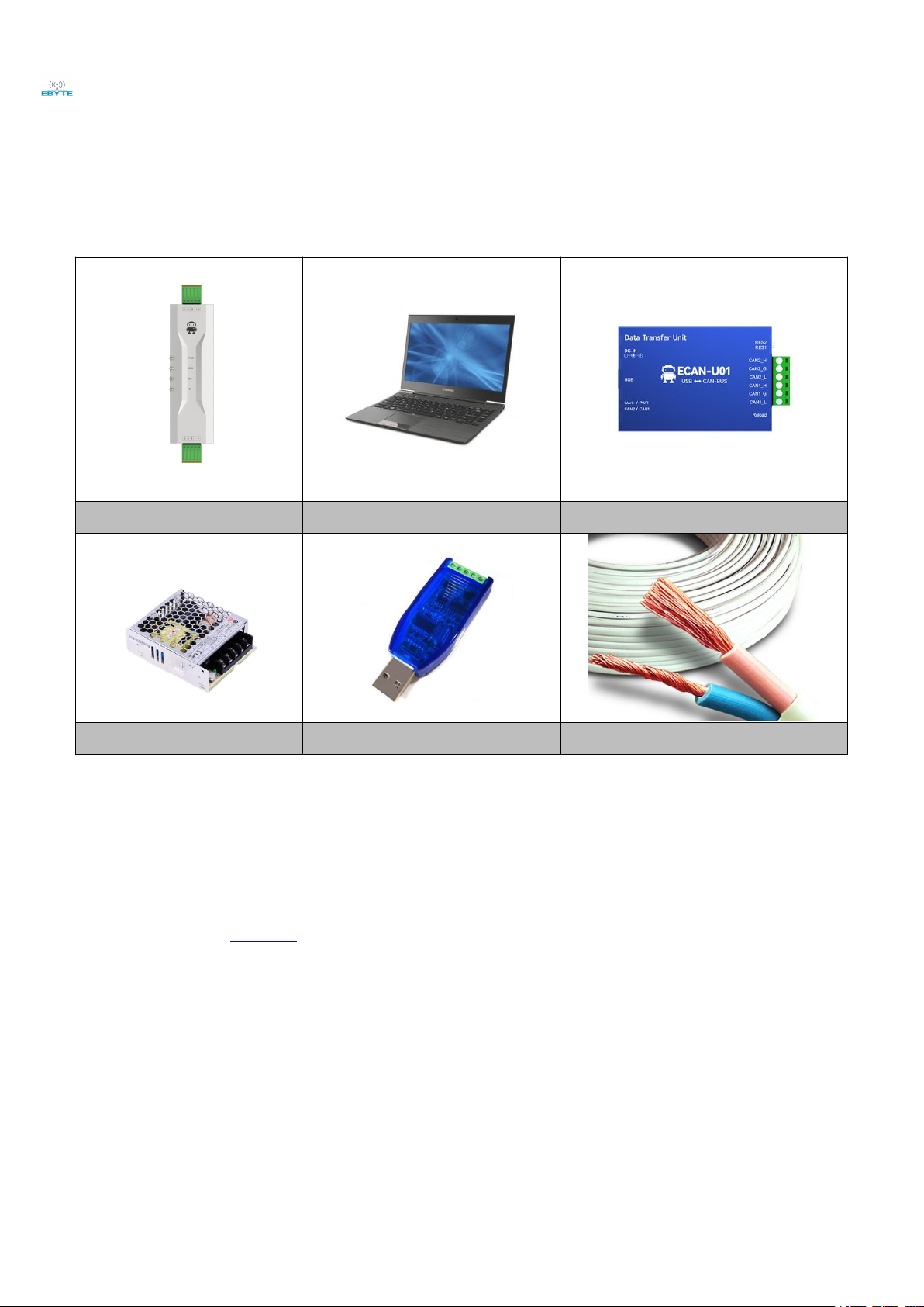
ECAN-101 is a small intelligent protocol conversion product independently developed by Chengdu Ebyte Electronic Technology Co., Ltd. The
product uses a wide voltage power supply of 8V ~ 28V and integrates 1 CAN-BUS interface and 1 RS485 interface, which can realize bidirectional
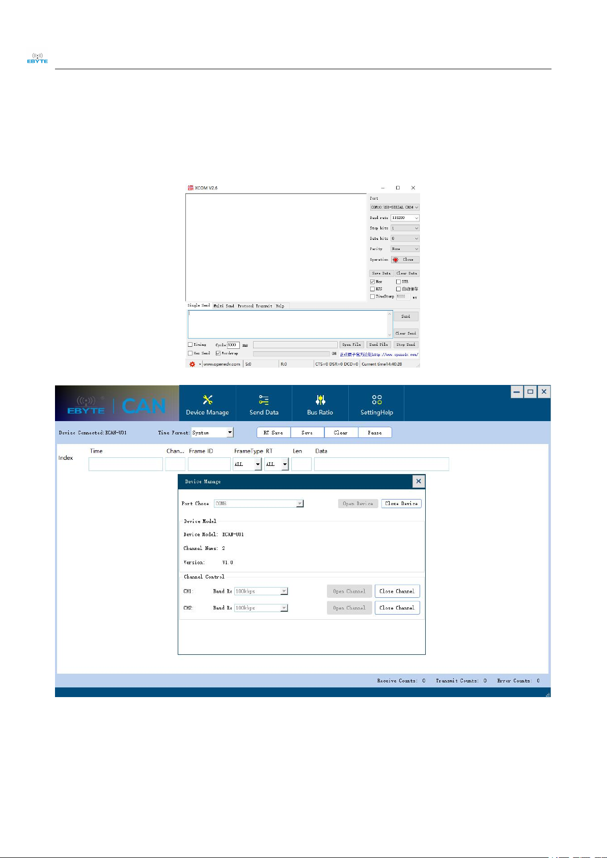
conversion between CAN and RS485 different protocol data. This product supports serial port AT command configuration and host computer
configuration of device parameters and working modes. It supports five data conversion modes: transparent conversion, transparent conversion with
logo, protocol conversion, Modbus RTU conversion, and customization (user). In MODBUS mode, It can play the role of a single CAN interface
replacing multiple 485 lines. At the same time, the ECAN-101 intelligent protocol converter has the characteristics of compact size and easy installation.
It has extremely high cost performance in CAN-BUS product development and data analysis applications. It is a reliable assistant for engineering
applications, project debugging and product development.
1.2 Features and functions
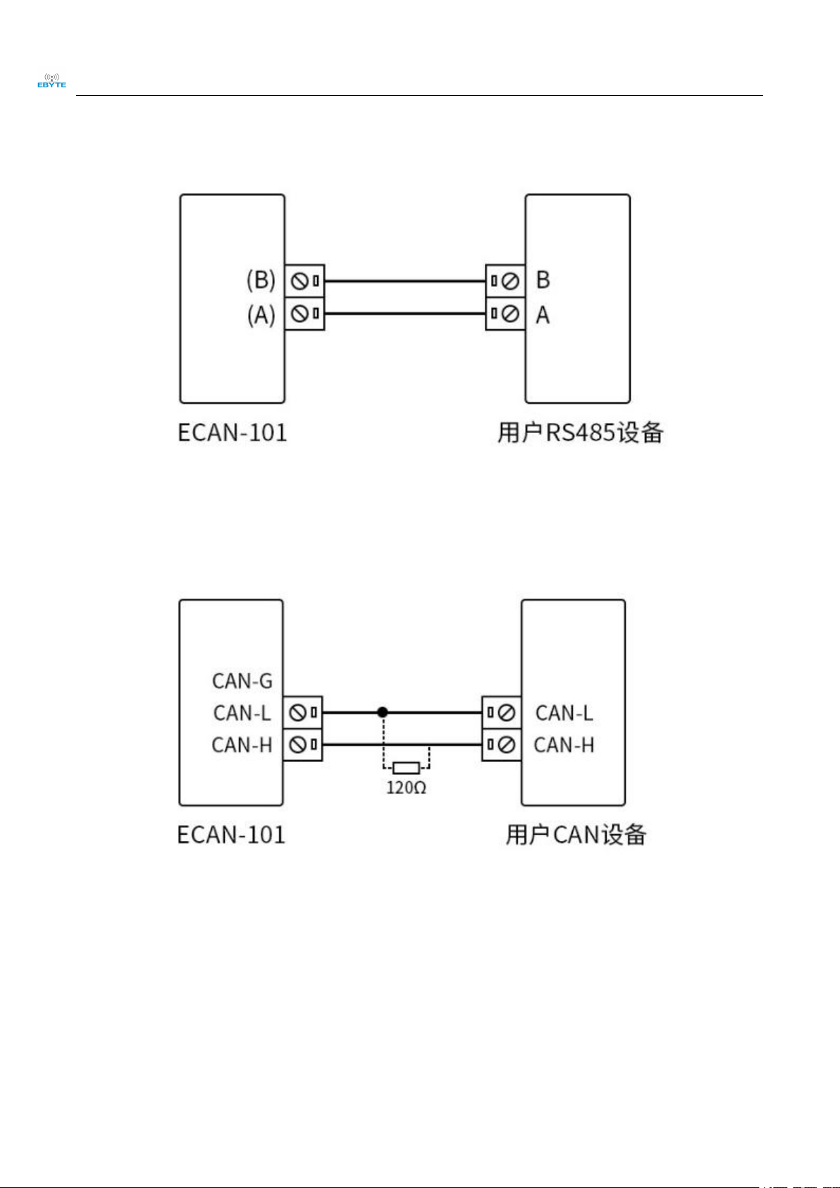
Bidirectional conversion between CAN and RS485 protocol data;
Support transparent conversion, transparent tape identification conversion, protocol conversion, Modbus RTU conversion, and custom
protocol conversion;
Support RS485 interface parameter configuration;
Support the configuration of AT command parameters;
Support the configuration of upper computer parameters;
Support AT commands, upper computer, and button recovery to factory settings;
Equipped with various status indicators such as power indicator light and status indicator light;
Multi master and multi slave function, replacing multi-channel 485 with a single CAN interface;
Equipped with a 120 ohm terminal resistor;
1.3 Application Scenario
Industrial control and other CAN-BUS networks
Networking of Automobile and Railway Equipment
Security and fire protection network
Underground remote communication
Public Address System
Parking lot equipment control
Smart home and smart building

Chengdu Ebyte Electronic Technology Co., Ltd. ECAN-101 User Manual
Copyright ©2012–2023,Chengdu Ebyte Electronic Technology Co., Ltd.
2. Product specifications and characteristics
2.1 Basic parameters
main parameter
specifications
supply voltage
DC 8V~28V, recommended for 12V or 24V power supply
Working current
9.5mA@12V (standby)
Interface type
Serial interface: RS485:2.5 spring terminal, crimping method
CAN interface: 2.5 spring terminals, crimping method
Interface characteristics
Serial interface: standard RS485 level interface, baud rate range: 600bps~460800bps
CAN interface: follows ISO 11898 standard, supports CAN2.0A/B, CAN baud rate range:
6Kbps~1000Kbps
CAN terminal resistance
Integrated, 2.5 spring terminals, crimping method, short circuiting R120+and R120- for use
Communication indicator light
On board power supply (PWR), error reporting (ERR), receiving (RX), sending (TX)
indicator lights
working temperature
-40 ℃~85 ℃, industrial grade
Working humidity
15% to 90% RH, without condensation
2.2 Factory default parameters
RS485
Serial Port Baud Rate
115200 bps
Parity check
none
Data bits
8
Stop bit
1
Flow control
close
CAN
CAN Baud Rate
100K bps
CAN ID
0x0000000
Default working mode
Transparent conversion mode
Receive all data types

Chengdu Ebyte Electronic Technology Co., Ltd. ECAN-101 User Manual
Copyright ©2012–2023,Chengdu Ebyte Electronic Technology Co., Ltd.
3. Quick start
Hardware preparation: USB to RS485 converter * 1, power supply * 1 (recommended DC 12V power supply), computer * 1, USB to CAN device * 1
ECAN-U01(recommended)
ECAN-101
computer
ECAN-U01
DC 12V switching power supply
USB to RS485
Several cables
Software preparation: You can download "Serial Port Assistant (X-COM)" in the "Related Downloads" of the official product website and configure
the host computer
3.1 Connecting devices
Here, using this device as ECAN-U01an example to demonstrate how to get started quickly.

Chengdu Ebyte Electronic Technology Co., Ltd. ECAN-101 User Manual
Copyright ©2012–2023,Chengdu Ebyte Electronic Technology Co., Ltd.
First, use a USB to RS485 converter to connect the device and the computer. The RS485_A and RS485_B of the converter correspond
to the RS485_A and RS485_B of the connected device; the USB end of the converter is directly connected to the computer;
Secondly, use ECAN-U01 to connect the device and the computer; the CAN end of ECAN-U01 is connected to the CAN end of the
device, CAN-L is connected to CAN-L, and CAN-H is connected to CAN-H. The USB end of ECAN-U01 is directly connected to the
computer.
Note: When using the USB to RS485 converter for the first time, you need to install software and drivers. Please consult the relevant
manufacturer for detailed usage..

Chengdu Ebyte Electronic Technology Co., Ltd. ECAN-101 User Manual
Copyright ©2012–2023,Chengdu Ebyte Electronic Technology Co., Ltd.
3.1.1 RS485 connection method
3.1.2 CAN connection method
The linear topology is the most commonly used in CAN bus wiring specifications. The two main lines branch out to each
node. Configure appropriate terminal resistors at both ends of the backbone to achieve impedance matching (typically
120 ohms within 2km).
According to the ISO 11898 specification, in order to enhance the reliability of CAN-bus communication, terminal matching resistors
(120 Ω) are usually added to the two endpoints of the CAN-bus network. The size of the terminal matching resistance is determined by
the characteristic impedance of the transmission cable. For example, if the characteristic impedance of a twisted pair is 120 Ω, the two
endpoints on the bus should also integrate a 120 Ω terminal resistance

Chengdu Ebyte Electronic Technology Co., Ltd. ECAN-101 User Manual
Copyright ©2012–2023,Chengdu Ebyte Electronic Technology Co., Ltd.
3.2 Device transparent debugging
After connecting the wires as described above, power on all equipment.
Open the serial port debugging assistant on the computer, select the serial port number used for the device's serial port (after entering
the software, select the serial port number connected to ECAN-101, and click "Connect Device" to establish the connection). If the
user does not know the serial port number, they can view it by entering the device manager of the PC And set the serial port
parameters as the device default parameters (baud rate 115200, 8 data bits, no parity bit, 1 stop bit);
Open ECAN-U01 to debug the upper computer and set the CAN baud rate to 100K (ECAN-101 defaults to the factory CAN baud rate);
After the above steps, the transparent conversion debugging can begin:
Firstly, convert the CAN frame to a serial frame:
The CAN debugger (ECAN-U01) sends data: frame ID: 0x0123, data domain: 99 88 77 66 55 44 33 22. The device CAN receives the
data sent by the CAN debugger (ECAN-U01) below, and the serial assistant displays the CAN data forwarded by the RS485 interface
(hexadecimal display): 99 88 77 66 55 44 33 22.

Chengdu Ebyte Electronic Technology Co., Ltd. ECAN-101 User Manual
Copyright ©2012–2023,Chengdu Ebyte Electronic Technology Co., Ltd.
Convert serial frames to CAN frames:
Send data in hexadecimal from the serial debugging assistant: 11 22 33 44 55 66 77 88. The data converted from the device CAN end can be displayed
in the CAN debugger (ECAN-U01) below. The data is: 11 22 33 44 55 66 77 88, frame ID: 0x0000, standard frame.
From the above debugging operation, it can be seen that the device has achieved transparent conversion between serial frames and CAN frames.
3.3 Upper computer configuration
The device can be configured with device parameters through AT commands or upper computer. Here is a brief introduction to the
usage of upper computer configuration.
1. To change the device parameters, open ECAN-101 to configure the upper computer, select the default serial port parameters (baud
rate 115200, 8 data bits, no parity bit, 1 stop bit), and click to open the serial port.

Chengdu Ebyte Electronic Technology Co., Ltd. ECAN-101 User Manual
Copyright ©2012–2023,Chengdu Ebyte Electronic Technology Co., Ltd.
2. Click on "Connect Device" to enter configuration mode and read parameters
3. The device's "serial port parameter settings", "CAN bus settings", "conversion direction", "conversion mode", "device filtering
settings" and other parameters can be changed according to different application scenarios. After modifying the parameters, click

Chengdu Ebyte Electronic Technology Co., Ltd. ECAN-101 User Manual
Copyright ©2012–2023,Chengdu Ebyte Electronic Technology Co., Ltd.
"write configuration" and "restart the device" to take effect.
Serial port parameter settings: This section is for serial port parameter settings, which are divided into "Baud rate",
"Check bit", and "Stop bit". The baud rate range is: 6001200240048009601440019200384004300057600, 76800, 115200, 128000,
230400, 256000, 460800 units: bps; Inspection bits: odd parity (ODD), even parity (EVEN), and no parity (NONE); Stop bits: 1, 2.

Chengdu Ebyte Electronic Technology Co., Ltd. ECAN-101 User Manual
Copyright ©2012–2023,Chengdu Ebyte Electronic Technology Co., Ltd.
CAN bus settings: This section is the CAN section settings, divided into "CAN baud rate", "frame category", and "frame
ID". The CAN baud rate range is 6K, 10K, 20K, 50K, 100K, 120K, 125K, 150K, 200K, 250K, 400K, 500K, 600K, 750K, and 1000K.
The unit is bps. If the baud rate set is inconsistent with the bus baud rate of the access module, normal communication conversion will
not be possible. Frame category: NDTF (standard frame), EDTF (extended frame), Frame ID: 0-7FF (standard frame), 0-1FFFFFFF
(extended frame)

Chengdu Ebyte Electronic Technology Co., Ltd. ECAN-101 User Manual
Copyright ©2012–2023,Chengdu Ebyte Electronic Technology Co., Ltd.
Conversion modes: There are five types: TRANS (transparent), TPRTL (transparent band identification), PROTOL
(protocol mode), USER (custom protocol), MODBUS (MODBUS). The protocol rules for each mode are different, as described in
Chapter 5.
Device filtering settings: There are four filtering methods: 1. Receive all data 2. Only receive extended frames 3. Only

Chengdu Ebyte Electronic Technology Co., Ltd. ECAN-101 User Manual
Copyright ©2012–2023,Chengdu Ebyte Electronic Technology Co., Ltd.
receive standard frames 4. User defined.
The first three options only require configuration selection, while the last user defined filter can add 14 sets of custom ID
filters. Click "Add Information", add the desired filtering ID in the left information box, and then click "Write" to complete.

Chengdu Ebyte Electronic Technology Co., Ltd. ECAN-101 User Manual
Copyright ©2012–2023,Chengdu Ebyte Electronic Technology Co., Ltd.
4. Introduction to Hardware Parameter Design
4.1 Design Introduction
Pin number
Pin Name
Pin Usage
1
PWR
Power indicator light, always on when powered on (red)
2
ERR
Error indicator light, bus error always on (red), bus recovery off
3
RX
Data indicator light, flashing (green) when receiving data through the serial port
4
TX
Data indicator light, serial port sending data, flashing (green)
5
Restore
Restore button, press and hold for more than 5 seconds to restore factory settings
6
GND
Signal ground
7
485-A
RS485 bus data A
8
485-B
RS485 bus data B
9
V-
Negative pole of power supply, DC 8V~28V, recommended 12V or 24V power
supply
10
V+
Positive pole of power supply, DC 8V~28V, recommended 12V or 24V power
supply
11
CAN_ L
CAN communication interface
12
CAN_ H
CAN communication interface
13
CAN_ G
CAN grounding
14
R+
120 ohm matching resistor positive, short circuited R120- for use
15
R-
120 ohms matching resistance negative, short circuited to R120+for use

Chengdu Ebyte Electronic Technology Co., Ltd. ECAN-101 User Manual
Copyright ©2012–2023,Chengdu Ebyte Electronic Technology Co., Ltd.
4.2 Dimensional drawing
5. Mode Description
During "transparent conversion" and "format conversion", a byte of frame information is used to identify some
information of the CAN frame, such as type, format, length, etc. The frame information format is as follows.
Frame information description
Bit7
Bit6
Bit5
Bit4
Bit3
Bit2
Bit1
Bit0
FF
RTR
NO
NO
DLC3
DLC2
DLC1
DLC0
Table 1.1 Frame Information
FF: Identification of standard and extended frames, with 0 being the standard frame and 1 being the extended frame;
RTR: Identification of remote frames and data frames, with 0 being the data frame and 1 being the remote frame;
NO: Not used;
NO: Not used;
DLC3~DLC0: Identify the data length of the CAN message;
5.1 Data conversion method
The ECAN-101 device supports five data conversion methods: transparent conversion, transparent tape identification conversion, protocol
conversion, MODBUS conversion, and custom protocol conversion. Supports bidirectional conversion between CAN and RS485.
Data conversion method
change direction
Transparent conversion
CAN and RS485 bidirectional conversion
Transparent tape identification conversion
CAN and RS485 bidirectional conversion
protocol conversion
CAN and RS485 bidirectional conversion
MODBUS conversion
CAN and RS485 bidirectional conversion
Custom Protocol Conversion
CAN and RS485 bidirectional conversion
5.1.1 Transparent conversion mode
Transparent conversion: The converter converts bus data from one format to another format without attaching or modifying data. This not only
achieves the exchange of data formats without changing the data content, but also makes the converter "transparent" to the buses at both ends, hence it
is called transparent conversion.

Chengdu Ebyte Electronic Technology Co., Ltd. ECAN-101 User Manual
Copyright ©2012–2023,Chengdu Ebyte Electronic Technology Co., Ltd.
The ECAN-101 device can convert valid data received from the CAN bus intact to the RS485 serial bus output. Similarly, the device can also
convert the valid data received from the RS485 serial bus to the CAN bus output intact. Realize transparent conversion between RS485 and CAN.
1. Serial frame to CAN message
All data of the serial frame is sequentially filled into the data domain of the CAN message frame. Once the module detects data on the serial bus,
it immediately receives and converts it. The converted CAN message frame information (frame type part) and frame ID come from the user's prior
configuration, and the frame type and frame ID remain unchanged during the conversion process.
CAN message
Frame
information
User
Configuratio
n
Serial
frame
Frame ID
User
Configuratio
n
0
Data 1
User
Configuratio
n
1
Data 2
Data Domain
Data 1
2
Data 3
Data 2
3
Data 4
Data 3
4
Data 5
Data 4
5
Data 6
Data 5
6
Data 7
Data 6
7
Data 8
Data 7
Data 8
Convert serial frames into CAN messages (transparent)
Conversion example:
Convert serial frames into CAN messages (transparently).
Assuming that the configuration CAN frame information is' standard frame ', frame ID is' 0x0213', and serial frame data is from 0x01 to 0x0C,
the conversion format is as follows. The frame ID of the CAN message is 0x0213 (user configured), and the frame category is standard frame (user
configured). The data part in the serial frame will be converted into the CAN message without any modification.
Convert
serial frames into
CAN
messages
(transparent)
Serial
frame
CAN
message 1
CAN
message 2
0x01
Frame
information
0x08
0x04
0x02
Frame ID
0x02
0x02
0x03
0x13
0x13
0x04
Data
Domain
0x01
0x09
0x05
0x02
0x0A
0x06
0x03
0x0B
0x07
0x04
0x0C
0x08
0x05
0x09
0x06
0x0A
0x07
0x0B
0x08
0x0C

Chengdu Ebyte Electronic Technology Co., Ltd. ECAN-101 User Manual
Copyright ©2012–2023,Chengdu Ebyte Electronic Technology Co., Ltd.
2. CAN message to serial frame
During conversion, all data in the CAN message data domain is sequentially converted into serial frames. If "Enable Frame Information" is
checked during configuration, the module will directly fill the "Frame Information" byte of the CAN message into the serial frame. If 'Enable Frame ID'
is checked, all 'Frame ID' bytes of the CAN message will also be filled in to the serial frame.
Note: If you want to receive CAN frame information or frame ID on the serial interface, you need to enable the corresponding function. Only
then can the corresponding information be received.
CAN message
Serial frame
Frame
informat
ion
User
Configurati
on
Frame
informat
ion
User Configuration
Frame
ID
User
Configurati
on
Frame
ID
User Configuration
User
Configurati
on
User Configuration
Data
Domain
Data 1
0
Data 1
Data 2
1
Data 2
Data 3
2
Data 3
Data 4
3
Data 4
Data 5
4
Data 5
Data 6
5
Data 6
Data 7
6
Data 7
Data 8
7
Data 8
Converting CAN messages into serial frames (transparent mode)
Conversion example:
The CAN message "frame information" enabled and "frame ID" enabled in this example configuration. Frame ID 1: 0x123, Frame Category:
Standard Frame, Frame Type: Data Frame. Conversion direction: bidirectional. The data is 0x12, 0x34, 0x56, 0x78, 0xAB, 0xCD, 0xEF, 0xFF. The
data before and after conversion is as follows:
CAN message
Serial frame
Frame
informat
ion
0x08
0x08
Frame
ID
0x01
0x01
0x23
0x23
Data
Domain
0x12
0x12
0x34
0x34
0x56
0x56
0x78
0x78
0xAB
0xAB
0xCD
0xCD
0xEF
0xEF
0xFF
0xFF
Converting CAN messages into serial frames (transparent mode)

5.1.2 Transparent tape identification mode
Transparent band identification conversion is a special use of transparent conversion. In the serial frame, the ID information of the CAN message
can be sent with different IDs as needed. It is beneficial for users to establish their own network more conveniently through modules and use
customized application protocols. This method automatically converts the ID information in the serial frame into the frame ID of the CAN bus. As long
as the module is told in the configuration that the ID information is at the starting position and length of the serial frame, the module extracts this frame
ID during conversion and fills it in the frame ID field of the CAN message, which is used as the ID of the CAN message when forwarding the serial
frame. When converting CAN messages into serial frames, the ID of the CAN message is also converted to the corresponding position in the serial
frame.
Conversion method:
1. Serial frame to CAN message
The starting address and length of the "frame ID" of the CAN message carried in the serial frame can be set by configuration. The starting
address range is 0-7, and the length range is 1-2 (standard frame) or 1-4 (extended frame). During conversion, all CAN message "frame IDs" in the
serial frame are converted into the frame ID domain of the CAN message according to the previous configuration. (If the number of frame IDs carried
is less than the number of frame IDs in the CAN message, the high byte of the frame ID in the CAN message is filled with 0.) Other data is sequentially
converted. If a CAN message does not fully convert the serial frame data, the same ID is still used as the frame ID of the CAN message to continue
conversion until the serial frame conversion is completed.
Note: If the ID length is greater than 2, the frame category sent by the device will be set to extended frames. At this point, the frame ID and
frame category configured by the user are invalid, determined by the data inside the serial frame. The frame ID range of standard frames is: 0x000-
0x7FF, represented as frame ID1 and frame ID0 respectively, where frame ID1 is a high byte, and the frame ID range of extended frames is:
0x00000000-0x1FFFFFFFF, represented as frame ID3, frame ID2, frame ID1, and frame ID0 respectively, where frame ID3 is a high byte.
Serial frame
CAN message
CAN message x
0
Data 1 (ID1)
Frame
informatio
n
User
Configuration
User
Configurati
on
1
Data 2 (ID0)
Frame ID
Data 1 (ID1)
Data 1 (ID1)
2
Data 3
Data 2 (ID0)
Data 2 (ID0)
3
Data 4
Data Domain
Data 3
data
4
Data 5
Data 4
Data N-1
5
Data 6
Data 5
Data N
6
Data 7
Data 6
7
Data 8
Data 7
…
…
Data 8
N-2
Data N-1
Data 9
N-1
Data N
Data 10
Convert serial frames into CAN messages (transparent with identification)
Conversion example:
Serial frame to CAN message (transparent tape identification).
The CAN configuration parameters for this example configuration. Conversion mode: Transparent tape identification conversion,
starting address 2, length 3. Frame type: Extended frame, Frame ID: No configuration required, Conversion direction: Bidirectional. The
upper computer configuration interface is as follows:
Table of contents
Other Ebyte Media Converter manuals
Popular Media Converter manuals by other brands

Omnitron Systems Technology
Omnitron Systems Technology OmniConverter GPoE+/S user manual

Speaka Professional
Speaka Professional 989340 operating instructions

Teleste
Teleste EASI user manual

TechniSat
TechniSat TechniNet BS5 Light Mounting instruction

Sealey
Sealey AUTO SERVICE LINE TL95 instructions

Manhattan
Manhattan 151436 instructions

Lindy
Lindy 38149 user manual

US Digital
US Digital EC35 Assembly and Timing Instructions

Decimator
Decimator MD-HX operating manual

Audio Note
Audio Note DAC 0.1x Homeowner's information

StarTech.com
StarTech.com HDMI2HDMI instruction manual

StarDental
StarDental DentalEZ Titan Blis-sonic K 264564 instruction manual