Ebyte E810-DTU User manual

E810-DTU(CAN-RS485)
Intelligent Protocol Converter

Chengdu Ebyte Electronic Technology Co.,LTD E810-DTU(CAN-RS485) User Manual
Copyright ©2012–2019,Chengdu Ebyte Electronic Technology Co., Ltd. 2
Contents
1. OVERVIEW..................................................................................................................................... 4
1.1 Brief Introduction........................................................................................................................................................... 4
1.2 Feature............................................................................................................................................................................. 4
1.3 Application...................................................................................................................................................................... 4
2. TECHNICAL PARAMETERS AND SPECIFICATION............................................................ 5
2.1 Basic parameter.............................................................................................................................................................. 5
2.2 Factory default parameter............................................................................................................................................. 5
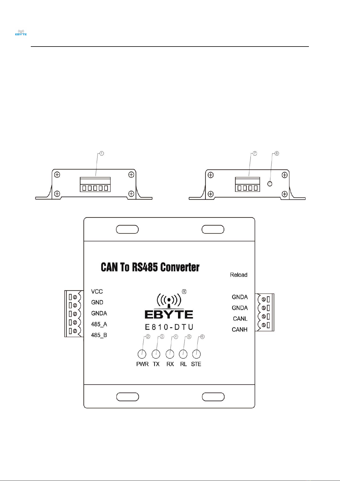
3 HARDWARE DESIGN INTRODUCTION................................................................................... 6
3.1 Design introduction.........................................................................................................................................................6
3.2 Dimension....................................................................................................................................................................... 8
3.3 Connection method......................................................................................................................................................... 9
3.3.1 RS485 connection method.........................................................................................................................................9
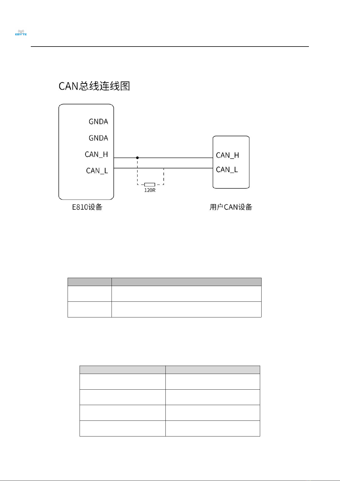
3.3.2 CAN connection method......................................................................................................................................... 10
4 MODE INTRODUCTION.............................................................................................................10
4.1 Operating mode.............................................................................................................................................................10
4.2 Data conversion method...............................................................................................................................................10
4.2.1Transparent conversion mode...................................................................................................................................11
4.2.2 Transparent band information conversion............................................................................................................... 14
4.2.3 Protocol mode..........................................................................................................................................................17
4.2.4 Modbus mode.......................................................................................................................................................... 19
5 OPERATION INSTRUCTIONS...................................................................................................22
5.1 Entering Command Configuration Instructions....................................................................................................... 22
5.2 Command overview...................................................................................................................................................... 22
5.3 Command error code....................................................................................................................................................22

Chengdu Ebyte Electronic Technology Co.,LTD E810-DTU(CAN-RS485) User Manual
Copyright ©2012–2019,Chengdu Ebyte Electronic Technology Co., Ltd. 3
5.4 Command list................................................................................................................................................................ 23
5.5 Command details.......................................................................................................................................................... 23
5.5.1 AT test command................................................................................................................................................... 23
5.5.2 AT+CANFLT Inquire/set CAN filter info............................................................................................................ 23
5.5.3 AT+CAN inquire/set transmitted CAN parameter info...........................................................................................24
5.5.4 AT+EXAT exit AT command..................................................................................................................................24
5.5.5 AT+E inquire/set command echo mode...................................................................................................................24
5.5.6 AT+MODBUSID inquire/set MODBUS ID........................................................................................................... 25
5.5.7 AT+MODE inquire/set operating mode................................................................................................................ 25
5.5.8 AT+MID inquire device name................................................................................................................................ 25
5.5.9 AT+RESTORE restore factory default setting....................................................................................................... 26
5.5.10 AT+REBT reset device.......................................................................................................................................... 26
5.5.11 AT+UARTPKT inquire/set UART sub=packing info........................................................................................... 26
5.5.12 AT+UART inquire/set UART parameter...............................................................................................................26
5.5.13 AT+VER inquire module version info..................................................................................................................27
6 FAQ..................................................................................................................................................27
6.1 Module is easy to damage.............................................................................................................................................27
6.2 Unable to successfully set the command..................................................................................................................... 27
6.3 Unable to use after parameter is changed.................................................................................................................. 27
REVISION HISTORY...................................................................................................................... 28
ABOUT US......................................................................................................................................... 28

Chengdu Ebyte Electronic Technology Co.,LTD E810-DTU(CAN-RS485) User Manual
Copyright ©2012–2019,Chengdu Ebyte Electronic Technology Co., Ltd. 4
1. Overview
1.1 Brief Introduction
E810-DTU (CAN-RS485) is a small intelligent protocol converter developed by
Chengdu Ebyte Electronic Technology Co., Ltd. It is with 8V ~ 28V of power supply,
integrating 1 channel CAN-BUS interface and 1 channel RS485 interface to realize
bidirectional conversion between different protocol data from RS485 and CAN. It supports
serial command configuration device parameters and working mode, and there are four data
conversion modes available: transparent conversion, transparent band information conversion,
protocol conversion, and Modbus RTU conversion. At the same time, E810-DTU (CAN-
RS485) intelligent protocol converter has the characteristics of small size and convenient
installation. It has high cost performance in CAN-BUS product development and data
analysis applications. It is reliable assistant for engineering application, project debugging and product development.
1.2 Feature
Bidirectional conversion of data between RS485 and CAN is available.
Transparent conversion, transparent band information conversion and protocol conversion are available.
Modbus RTU protocol conversion is available.
Support two CAN identifier transmission methods, which can be specified by fixed configuration or serial frame data.
Parameter setting via RS485 is available.
Parameter setting via RS485 is between 1200~115200.
Parameter setting via software is available.
Factory setting reset via software and hardware is available.
With power indicator, status indicator, etc.
1.3 Application
Industrial control and other CAN-BUS networks
Automobile and railway equipment networking
Security and fire protection network
Underground remote communication
Public address system
Parking equipment control
Smart home, smart building

Chengdu Ebyte Electronic Technology Co.,LTD E810-DTU(CAN-RS485) User Manual
Copyright ©2012–2019,Chengdu Ebyte Electronic Technology Co., Ltd. 5
2. Technical Parameters and Specification
2.1 Basic parameter
Main parameter
Value
Power supply
8V ~28V ,12V or 24V is recommended (Voltage over 28V will cause
permanent damage)
Operating current
38.2762mA@12V(RS485)
Operating temperature
-40℃~85℃
Interface
RS485:1*5*3.81,screwing;CAN:1*4*3.81,screwing
Communication level
3.3V,or 5V,level switch is required
Operating humidity
10%~90%,relative humidity, no condensation
2.2 Factory default parameter
RS485
Serial baud rate
115200 bps
Parity
None
Data bit
8
Stop bit
1
Flow control
Off
CAN
CAN baud rate
100K bps
CAN ID
0x00000000
Flow control
Off
Default operating mode
Transparent transmission mode
Receive all kinds of data
Default device address
Modbus device address
Default device address is 1
Frame sub-packing parameter
Time
10ms
Byte
1000byte

Chengdu Ebyte Electronic Technology Co.,LTD E810-DTU(CAN-RS485) User Manual
Copyright ©2012–2019,Chengdu Ebyte Electronic Technology Co., Ltd. 6
3 Hardware design introduction
3.1 Design introduction

Chengdu Ebyte Electronic Technology Co.,LTD E810-DTU(CAN-RS485) User Manual
Copyright ©2012–2019,Chengdu Ebyte Electronic Technology Co., Ltd. 7
NO.
Item
Application
1
VCC
Power supply, default : 8-28V, 12V or 24V is recommended
(standard 5V can be customized )
2
GND
Ground
3
GNDA
RS485 common port,connecting to GND of other RS485 device
4
485_A
RS485, Data A
5
485_B
RS485, Data B
6
PWR
Power indicator
7
TX
Serial port TX indicator
8
RX
Serial port RX indicator
9
RL
Restore factory settings indicator, press DTU for 5-10S to restore factory
settings
10
STE
Status indicator
11
GNDA
Signal reference ground
12
GNDA
Signal reference ground
13
CAN-H can H
CAN communication interface
14
CAN-L can L
CAN communication interface

Chengdu Ebyte Electronic Technology Co.,LTD E810-DTU(CAN-RS485) User Manual
Copyright ©2012–2019,Chengdu Ebyte Electronic Technology Co., Ltd. 8
3.2 Dimension

Chengdu Ebyte Electronic Technology Co.,LTD E810-DTU(CAN-RS485) User Manual
Copyright ©2012–2019,Chengdu Ebyte Electronic Technology Co., Ltd. 9
3.3 Connection method
3.3.1 RS485 connection method

Chengdu Ebyte Electronic Technology Co.,LTD E810-DTU(CAN-RS485) User Manual
Copyright ©2012–2019,Chengdu Ebyte Electronic Technology Co., Ltd. 10
3.3.2 CAN connection method
4 Mode introduction
4.1 Operating mode
There are two modes for E810-DTU(CAN-RS485),normal and parameter setting mode.
Mode
Function
Normal mode
The general mode of the device is normal mode, and it works
normally when it is powered on.
Setting mode
The device can be configured in the mode. For details on how to
enter the configuration mode, see Chapter 5.
4.2 Data conversion mode
There are four data conversion modes for E810-DTU(CAN-RS485) :Transparent conversion, transparent band information
conversion, protocol conversion and MODBUS conversion. Bidirectional conversion between CAN and RS485 is available.
Data conversion mode
Conversion direction
Transparent conversion
Bidirectional conversion between CAN
and RS485
Transparent band information
conversion
Bidirectional conversion between CAN
and RS485
Protocol conversion
Bidirectional conversion between CAN
and RS485
MODBUS conversion
Bidirectional conversion between CAN
and RS485

Chengdu Ebyte Electronic Technology Co.,LTD E810-DTU(CAN-RS485) User Manual
Copyright ©2012–2019,Chengdu Ebyte Electronic Technology Co., Ltd. 11
4.2.1Transparent conversion mode
Transparent conversion: The converter converts the bus data of one format to the data format of another bus as it is,
without adding data or modifying it. The data format is exchanged without changing the data content. For the bus at both
ends, the converter is like "transparent".
The E810-DTU(CAN-RS485) can convert the valid data received by the CAN bus to RS485, and the UART outputs
the same data. Similarly, the module can also convert the data received by the RS485 to the CAN bus, and realize
transparent conversion between RS485 and CAN.
1. Frames in UART converts to CAN message
All data in the UART frames is sequentially filled into the data field of the CAN message frame. The converter
receives and converts as soon as it detects that there is data on the serial bus.The frame type and frame ID of the
converted CAN message come from the user's prior configuration, and the frame type and frame ID remain unchanged
during the conversion process. The corresponding format of data conversion is shown in Figure 4.1
If the received serial frame length is less than or equal to 8 bytes, the characters 1 to n (n is the serial frame length)
are sequentially filled into the 1 to n byte position of the data field of the CAN message (as shown in Figure 4.1, n is 7).
If the frame length is greater than 8, starting from the first character of the serial frame, for the first time the
processor takes 8 characters to fill the data field of the CAN message in turn; after the data is sent to the CAN bus, the
conversion is performed. The remaining serial frame data is filled into the data field of the CAN message until its data is
completely converted.
Figure 4.1 Frames in UART converts to CAN message(Transparent conversion)
For example:
Assume that the configured conversion into CAN message frame information is "standard frame" and the frame ID (ID1, ID2) is
set to 0060, then the conversion format is shown in Figure 4.2.

Chengdu Ebyte Electronic Technology Co.,LTD E810-DTU(CAN-RS485) User Manual
Copyright ©2012–2019,Chengdu Ebyte Electronic Technology Co., Ltd. 12
Figure 4.2 Frames in UART converts to CAN message(Transparent conversion)
2. CAN message converts to frames in UART
All data in the data field of the CAN message frame is sequentially filled into the serial frame data; the converter
receives and converts immediately after detecting the data on the CAN bus.
Figure 4.3 CAN message converts to frames in UART (Transparent conversion)

Chengdu Ebyte Electronic Technology Co.,LTD E810-DTU(CAN-RS485) User Manual
Copyright ©2012–2019,Chengdu Ebyte Electronic Technology Co., Ltd. 13
For example:
Assume that the CAN message frame information is "standard frame" and the frame ID (ID1, ID2) is set to 0060, then the
conversion format is shown in Figure 4.4.
Figure 4.4 CAN message converts to frames in UART (Transparent conversion)

4.2.2 Transparent band information conversion
Transparent band information conversion is a special use of transparent conversion without any protocol attached.
This conversion method is based on the common characteristics of the usual serial frame and CAN message, so that the
two different bus types can easily form a same communication network.
In this mode, the CAN bus receiver can add the received frame information of the CAN message and the frame ID
to the converted serial frame. In this way, the receiver can clearly see the sender's CAN message to ensure more flexible
use.
Conversion method:
1. Frames in UART converts to CAN message
With the transparent conversion, all the data of the serial frame is sequentially filled into the data field of the CAN
message frame. The converter receives and converts as soon as it detects that there is data on the serial bus.
The frame type and frame ID of the converted CAN message come from the user's prior configuration, and the
frame type and frame ID remain unchanged during the conversion process. The corresponding format of data conversion
is shown in Figure 4.5.
If the received serial frame length is less than or equal to 8 bytes, the characters 1 to n (n is the serial frame length)
are sequentially padded to the 1 to n byte position of the data field of the CAN message (as shown in the figure 4.5, n is
8).
If the number of bytes of the serial frame is greater than 8, starting from the first character of the serial frame, for
the first time the processor takes 8 characters to fill the data field of the CAN message in turn; The data is sent to the
CAN bus before the conversion is performed. The remaining serial frame data is filled into the data field of the CAN
message until its data is completely converted.
Figure 4.5 Frames in UART converts to CAN message(Transparent band information conversion)
For example:
Assume that the frame information converted into CAN message is "standard frame" and the frame ID (ID1,
ID2) is set to 0060, then the conversion format is as shown in the figure below.

Chengdu Ebyte Electronic Technology Co.,LTD E810-DTU(CAN-RS485) User Manual
Copyright ©2012–2019,Chengdu Ebyte Electronic Technology Co., Ltd. 15
。
Figure 4.6 Frames in UART converts to CAN message(Transparent band information conversion)
2. CAN message converts to frames in UART
Once data is detected on the CAN bus via the converter, it is immediately received and converted. When the
converter receives a frame of CAN message, the frame is immediately converted . Whenever the conversion, the CAN
frame information and the frame ID are added to the serial frame. The conversion is the same as the CAN message to
serial frame of the following protocol mode. For details, please refer to the protocol mode), as shown in the figure 4.7.
Please note: whether the serial frame or CAN message is applied at the time of its frame format (standard frame or
extended frame) should meet the previously configured frame format requirements, otherwise communication may fail.

Chengdu Ebyte Electronic Technology Co.,LTD E810-DTU(CAN-RS485) User Manual
Copyright ©2012–2019,Chengdu Ebyte Electronic Technology Co., Ltd. 16
Figure 4.7 CAN message converts to frames in UART(Transparent band information conversion)
CAN transmit:
Frame format:extension frames
Frame type:data frames
ID :0x12345678
Data :AAh BBh CCh DDh EEh
Frames in UART receive:85 12 34 56 78 AA BB CC DD EE 00 00 00
0x85 indicates that the frame format is an extended frame, the frame type is a data frame, and the data length is 5
The last four digits indicate that the CAN ID is 12345678.
The last 8 bits are the data area, the effective length is 5, and the remaining bits are filled with 0.
Figure 4.8 CAN message converts to frames in UART(Transparent band information conversion)

Chengdu Ebyte Electronic Technology Co.,LTD E810-DTU(CAN-RS485) User Manual
Copyright ©2012–2019,Chengdu Ebyte Electronic Technology Co., Ltd. 17
4.2.3 Protocol mode
The data conversion format of E810-DTU(CAN-RS485) module is as follows. Each CAN frame contains 13 bytes,
and the 13-byte contents include CAN frame information + frame ID + frame data.
Frame information: 1 byte in length, used to identify some information of the CAN frame, such as type, length, etc.
FF
RTR
N/C
N/C
D3
D2
D1
D0
BIT7 BIT0
FF:The identification bits of the standard frame and the extended frame, where 1 is an extended frame and 0 is a standard frame.
RTR:The identification bits of the remote frame and data frame, 1 is the remote frame and 0 is the data frame.
N/C:value is 0,cannot write 1.
D3~D0:The data length bit identifies the data length of the CAN frame.
Frame ID:The length is 4 bytes, the standard frame valid bit is 11 bits, and the extended frame valid bit is 29 bits.
High byte Low byte High byte Low byte
The above is the extended frame ID number. The above is the standard frame ID number.
0x12345678 is the format 0x123 is the format
Frame data:The length is 8 bytes, and the effective length is determined by the value of D3~D0 of the frame information.
DATA1
DATA8
11h
22h
33h
44h
55h
66h
77h
88h
The above is the 8 bytes valid data format.
DATA1
DATA8
11h
22h
33h
44h
55h
00h
00h
00h
The above is the 5 bytes valid data format.
For example:
Below is the extended frame,frame ID is 0x11223344,8 bytes valid data format.
(11h,22h,33h,44h,55h,66h,77h,88h).
12h
34h
56h
78h
00h
00h
01h
23h
CAN frame
CAN frame
CAN frame
CAN frame
CAN frame

Chengdu Ebyte Electronic Technology Co.,LTD E810-DTU(CAN-RS485) User Manual
Copyright ©2012–2019,Chengdu Ebyte Electronic Technology Co., Ltd. 18
88h
11h
22h
33h
44h
11h
22h
33h
44h
55h
66h
77h
88h
Below is the standard frame,frame ID is 0x789,5 bytes valid data format(12h,34h,56h,78h,90h).
05h
00h
00h
07h
89h
12h
34h
56h
78h
90h
00h
00h
00h
Please note:every frame contains 13 bytes,add 0 if bytes are not enough, otherwise, communication may fail.
For example:
1. CAN message converts to frames in UART:
CAN transmits:
Frame format:extension frames
Frame type:data frames
ID :0x12345678
Data :AAh BBh CCh DDh EEh
Frames in UART receives:85 12 34 56 78 AA BB CC DD EE 00 00 00
0x85 indicates that the frame format is an extended frame, the frame type is a data frame, and the data length is 5
The last four digits indicate that the CAN ID is 12345678.
The last 8 bits are the data area, the effective length is 5, and the remaining bits are filled with 0, as shown below,
2. Frames in UART converts to CAN message:
Frames in UART transmit:05 00 00 06 78 12 34 56 78 90 00 00 00
0x05 indicates that the frame format is a standard frame, the frame type is a data frame, and the data length is 5.
00 00 06 78 indicates ID is 0678
12 34 56 78 90 00 00 00 is data field,valid length is 5,as shown below:

Chengdu Ebyte Electronic Technology Co.,LTD E810-DTU(CAN-RS485) User Manual
Copyright ©2012–2019,Chengdu Ebyte Electronic Technology Co., Ltd. 19
4.2.4 Modbus mode
Modbus conversion mode supports RTU conversion mode. The E810-DTU(CAN-RS485) module is used as a slave
device to receive and respond to commands sent by the host (via the UART).
The E810-DTU(CAN-RS485) conversion module supports two Modbus commands: read register (function code 03)
and write multiple registers (function code 16).
A buffer is internally built in the conversion module for buffering the received CAN frame data, and the buffer has a
total of 64 levels of buffer according to the addresses 0~63. The cache address starts from 0 to address 63, and can
continuously buffer 8 frames of CAN data (8 bytes per frame, a total of 64 bytes). When the first frame of CAN data is
received, the CAN frame data is stored in address 0, and the received CAN frame data is sequentially stored in increasing
order according to the address. If the 64-level cache is full, the newly received CAN frame data will be stored in address
0 and overwrite the original number, following FIFO.
Read register (function code 03):
Send command:
[Device Address] [Command No. 03 (0x03)] [Start Register Address is 8 Bits High] [8 Bits Low] [Read Register
Numbers is 8 Bits High] [8 Bits Low]
[High 8 bits of CRC check] [Lower 8 bits of CRC check]
The read format is only allowed to read 00 08 from address 00 00 (one byte of data is read at a time, that is, data of 00
00 – 00 07 address is read), after reading successfully, the 8 The byte data will be emptied, and the data after its address
will move forward by 8 data.
such as:
When the module in MODBUS mode, the CAN bus receives 4 frames of data:
First frame: 0x01 0x02 0x03 0x04 Total: 4 bytes of data
Second frame: 0x0A 0x0B 0x0C 0x0D 0x0E 0x0F Total: 6 bytes of data
Third frame: 0x11 0x22 0x33 0x44 0x55 0x66 0x77 0x88 Total:8 bytes of data
Fourth frame: 0XAA 0XBB 0XCC Total: 3 bytes of data
They are stored in the MODBUS cache address:

Chengdu Ebyte Electronic Technology Co.,LTD E810-DTU(CAN-RS485) User Manual
Copyright ©2012–2019,Chengdu Ebyte Electronic Technology Co., Ltd. 20
(The address without data is 0x00)
With the command: 01 03 00 00 00 08 (in the slave device with address 01, read 8 data starting from address 0000)
Write this command to the special tool (Modbus CRC 16 calculator) to calculate the CRC check. The value is added after
the instruction. This command is issued via the UART: 01 03 00 00 00 08 44 0C. When the slave receives the instruction,
it returns the buffer value inside the slave conversion module. (When no new CAN frame data is received, the cache
value read by the host is all 0)
Return instruction:
[Device Address] [Command No. 03] [Number of Bytes Returned] [Data 1] [Data 2]...[Data n] [High 8 bits of CRC
check] [Low 8 bits of CRC check]
Such as:
Once the slave receives instruction 01 03 00 00 00 08 44 0C,it returns:
01 03 10 00 01 00 02 00 03 00 04 00 00 00 00 00 00 00 00 1F 9F
After the reading is completed, the 8 bytes of data are emptied, and the data after the address is moved forward by 8
data. As shown below:
Other manuals for E810-DTU
4
Table of contents
Other Ebyte Media Converter manuals