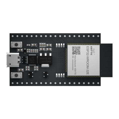
Ebyte ESP32-S3-WROOM Series User manual

1
ESP32-S3-WROOM Series
Development Board
User Manual

Chengdu Ebyte Electronic Technology Co., Ltd. ESP32-S3-WROOM Series Development Board User Manual
Copyright © 2012 , Chengdu Ebyte Electronic Technology Co., Ltd.
2
Contents
Disclaimer and Copyright Notice ..................................................................................................................................... 1
1. Module introduction ......................................................................................................................................................2
1.1 Feature introduction ............................................................................................................................................ 2
1.2 Parameter introduction ........................................................................................................................................2
2. Brief description of functions ....................................................................................................................................... 3
2.1 Component Introduction ..................................................................................................................................... 3
2.2 Pin definition .......................................................................................................................................................4
2.3 Function introduction ..........................................................................................................................................6
3 . Notes for developing applications ............................................................................................................................... 6
4 . Revision History .......................................................................................................................................................... 7

Chengdu Ebyte Electronic Technology Co., Ltd. ESP32-S3-WROOM Series Development Board User Manual
Copyright © 2012 , Chengdu Ebyte Electronic Technology Co., Ltd.
1
Disclaimer and Copyright Notice
Information in this document, including URL references, is subject to change without notice. The
documentation is provided "as is" without any warranty of any kind, including any warranties of
merchantability, fitness for a particular purpose, or non-infringement, and any warranties mentioned
elsewhere in any proposal, specification, or sample. This document disclaims any responsibility,
including liability for infringement of any patent rights arising out of the use of the information in this
document. No license, express or implied, to any intellectual property right is hereby granted by this
document, whether by estoppel or otherwise.
The test data obtained in this article are all obtained from Ebyte laboratory testing, and the actual
results may be slightly different.
All trade names, trademarks and registered trademarks mentioned herein are the property of their
respective owners and are hereby declared.
The final interpretation right belongs to Chengdu Ebyte Electronic Technology Co., Ltd.
Note :
Due to product version upgrades or other reasons, the contents of this manual may change. Ebyte Electronic Technology Co., Ltd.
reserves the right to modify the contents of this manual without any notice or prompt. This manual is only used as a guide. Chengdu
Ebyte Electronic Technology Co., Ltd. makes every effort to provide accurate information in this manual, but Chengdu Ebyte Electronic
Technology Co., Ltd. does not guarantee that the content of the manual is completely error-free. All statements in this manual ,
information and advice do not constitute any express or implied warranty.

Chengdu Ebyte Electronic Technology Co., Ltd. ESP32-S3-WROOM Series Development Board User Manual
Copyright © 2012 , Chengdu Ebyte Electronic Technology Co., Ltd.
2
1. Module introduction
1.1 Feature introduction
Figure 1 Actual picture of the module
ESP32-S3-WROOM-1-TB & ESP32-S3-WROOM-1U-TB are two entry-level development boards equipped
with Wi-Fi + Bluetooth® LE modules ESP32-S3-WROOM-1, ESP32-S3-WROOM-1U . This development board
has complete Wi-Fi and low-power Bluetooth functions , and most of the pins of the modules on the board have been
led to pin headers on both sides. Developers can easily connect various peripherals through jumpers according to
actual needs. equipment, and the development board can also be used on a breadboard.
1.2 Parameter introduction
serial
num
ber
parameter
name
parameter value
Comment
1
Support
module
ESP32-S3-WROOM-1
ESP32-S3-WROOM-1U
WiFi serial port module
2
Module size
62.74 * 25.4mm _
With USB connector
3
Production
Process
Lead-free process,
machine-mounted
Wireless products must be machine-mounted to ensure batch
consistency and reliability.
4
power supply
interface
USB
-
5
Communicatio
n Interface
TTL
-
6
Operating
temperature
-40 ~ +85℃
industrial grade
7
Working
humidity
10% ~ 90%
relative humidity, non-condensing
8
Storage
temperature
-40 ~ +125℃
industrial grade

Chengdu Ebyte Electronic Technology Co., Ltd. ESP32-S3-WROOM Series Development Board User Manual
Copyright © 2012 , Chengdu Ebyte Electronic Technology Co., Ltd.
3
2. Brief description of functions
2.1 Component Introduction
Figure 2 Main Component Diagram
serial
numb
er
main firmware
introduce
1
ESP32-S3-WROOM-1 &
ESP32-S3-WROOM-1 U
ESP32-S3-WROOM-1, ESP32-S3-WROOM-1U and
ESP32-S3-WROOM-2 are general-purpose Wi-Fi + Bluetooth
low-power MCU modules with rich peripheral interfaces and powerful
neural network operations capabilities and signal processing
capabilities, specifically built for the artificial intelligence and AIoT
markets. ESP32-S3-WROOM-1 and ESP32-S3-WROOM-2 use PCB
on-board antennas, and ESP32-S3-WROOM-1U uses a connector to
connect to an external antenna.
2
5 V to 3.3 V LDO
Power converter, input 5 V, output 3.3 V.
3
Pin
All available GPIO pins (except the SPI bus of the flash) have been led
out to the pin headers of the development board. Please see Pin Headers
for more information.
4
USB to UART interface
The Micro-USB interface can be used as the power supply interface of
the development board, can burn firmware to the chip, and can also be
used as a communication interface to communicate with the chip
through the onboard USB-to-UART bridge.
5
Boot key
Download button. Press and hold the Boot button and press the Reset
button to enter the "firmware download" mode and download the
firmware through the serial port.
6
ESP32-S3 USB interface
ESP32-S3 USB OTG interface supports full-speed USB 1.1 standard.
The ESP32-S3 USB interface can be used as the power supply interface
of the development board, can burn firmware to the chip, can
communicate with the chip through the USB protocol, and can also be
used for JTAG debugging.

Chengdu Ebyte Electronic Technology Co., Ltd. ESP32-S3-WROOM Series Development Board User Manual
Copyright © 2012 , Chengdu Ebyte Electronic Technology Co., Ltd.
4
Note: In the development board of the onboard ESP32-S3-WROOM-1/1U module series (using 8-line SPI flash/PSRAM), the pins
GPIO35, GPIO36 and GPIO37 have been used for the internal ESP32-S3 chip and SPI flash/PSRAM Communication between PSRAMs
is not available externally.
2.2 Pin definition
The picture below shows the front view of ESP32-S3-WROOM-1-TB&ESP32-S3-WROOM-1U-TB:
Figure 3 Current test interface diagram
7
Reset key
Reset button.
8
USB to UART bridge
Single-chip USB to UART bridge providing transfer rates up to 3
Mbps.
9
RGB LEDs
Addressable RGB LEDs driven by GPIO38.
10
3.3 V Power LED
After the development board is connected to the USB power supply, the
indicator light turns on.

Chengdu Ebyte Electronic Technology Co., Ltd. ESP32-S3-WROOM Series Development Board User Manual
Copyright © 2012 , Chengdu Ebyte Electronic Technology Co., Ltd.
5
pin number
Pin name
type
Pin usage
1
G
G
grounding
2
G
G
grounding
3
RST
I
EN
4
4
I/O/T
RTC_GPIO4, GPIO4, TOUCH4, ADC1_CH3
5
5
I/O/T
RTC_GPIO5, GPIO5, TOUCH5, ADC1_CH4
6
6
I/O/T
RTC_GPIO6, GPIO6, TOUCH6, ADC1_CH5
7
7
I/O/T
RTC_GPIO7, GPIO7, TOUCH7, ADC1_CH6
8
15
I/O/T
RTC_GPIO15, GPIO15, U0RTS, ADC2_CH4,
XTAL_32K_P
9
16
I/O/T
RTC_GPIO16, GPIO16, U0CTS, ADC2_CH5,
XTAL_32K_N
10
17
I/O/T
RTC_GPIO17, GPIO17, U1TXD, ADC2_CH6
11
18
I/O/T
RTC_GPIO18, GPIO18, U1RXD, ADC2_CH7,
CLK_OUT3
12
8
I/O/T
RTC_GPIO8, GPIO8, TOUCH8, ADC1_CH7,
SUBSPICS1
13
3
I/O/T
RTC_GPIO3, GPIO3, TOUCH3, ADC1_CH2
14
46
I/O/T
GPIO46
15
9
I/O/T
RTC_GPIO9, GPIO9, TOUCH9, ADC1_CH8,
FSPIHD, SUBSPIHD
16
10
I/O/T
RTC_GPIO10, GPIO10, TOUCH10, ADC1_CH9,
FSPICS0, FSPIIO4, SUBSPICS0
17
11
I/O/T
RTC_GPIO11, GPIO11, TOUCH11, ADC2_CH0,
FSPID, FSPIIO5, SUBSPID
18
12
I/O/T
RTC_GPIO12, GPIO12, TOUCH12, ADC2_CH1,
FSPICLK, FSPIIO6, SUBSPICLK
19
13
I/O/T
RTC_GPIO13, GPIO13, TOUCH13, ADC2_CH2,
FSPIQ, FSPIIO7, SUBSPIQ
20
14
I/O/T
RTC_GPIO14, GPIO14, TOUCH14, ADC2_CH3,
FSPIWP, FSPIDQS, SUBSPIWP
twenty one
19
I/O/T
RTC_GPIO19, GPIO19, U1RTS, ADC2_CH8,
CLK_OUT2, USB_D-
twenty two
20
I/O/T
RTC_GPIO20, GPIO20, U1CTS, ADC2_CH9,
CLK_OUT1, USB_D+
twenty three
G
G
grounding
twenty four
TX
I/O/T
U0TXD, GPIO43, CLK_OUT1
25
RX
I/O/T
U0RXD, GPIO44, CLK_OUT2
26
1
I/O/T
RTC_GPIO1, GPIO1, TOUCH1, ADC1_CH0
27
2
I/O/T
RTC_GPIO2, GPIO2, TOUCH2, ADC1_CH1
28
42
I/O/T
MTMS, GPIO42
29
41
I/O/T
MTDI, GPIO41, CLK_OUT1
30
40
I/O/T
MTDO, GPIO40, CLK_OUT2
31
39
I/O/T
MTCK, GPIO39, CLK_OUT3, SUBSPICS1
32
38
I/O/T
GPIO38, FSPIWP, SUBSPIWP, RGB LEDs

Chengdu Ebyte Electronic Technology Co., Ltd. ESP32-S3-WROOM Series Development Board User Manual
Copyright © 2012 , Chengdu Ebyte Electronic Technology Co., Ltd.
6
33
37
I/O/T
SPIDQS, GPIO37, FSPIQ, SUBSPIQ
34
36
I/O/T
SPIIO7, GPIO36, FSPICLK, SUBSPICLK
35
35
I/O/T
SPIIO6, GPIO35, FSPID, SUBSPID
36
0
I/O/T
RTC_GPIO0, GPIO0
37
45
I/O/T
GPIO45
38
48
I/O/T
GPIO48, SPICLK_N, SUBSPICLK_N_DIFF
39
47
I/O/T
GPIO47, SPICLK_P, SUBSPICLK_P_DIFF
40
twenty one
I/O/T
RTC_GPIO21, GPIO21
41
5V
P
5 V power supply
42
G
G
grounding
43
G
G
grounding
44
G
G
grounding
Note: 1. P: power supply; I: input; O: output; T: can be set to high impedance .
2.3 Function introduction
ESP32-S3-WROOM-1-TB&ESP32-S3-WROOM-1U-TB The main components and connections are shown in the figure
below:
3 . Notes for developing applications
Before powering on, please make sure that ESP32-S3-WROOM-1-TB &
ESP32-S3-WROOM-1U-TB are intact.
Preparation tools: ESP32-S3-MINI-1-TB or ESP32-S3-MINI-1U-TB, USB 2.0 data cable
(standard A type to Micro-B type , computer (Windows, Linux or macOS). ( Please make sure to
use Appropriate USB data cable, some data cables can only be used for charging and cannot be
used for data transfer and programming.)

Chengdu Ebyte Electronic Technology Co., Ltd. ESP32-S3-WROOM Series Development Board User Manual
Copyright © 2012 , Chengdu Ebyte Electronic Technology Co., Ltd.
7
4 . Revision History
Version
Revision date
Revision Notes
Maintenance man
1.0
2022-10-27
initial version
Hao
Contact Us:
Technical support: support@cdebyte.com
Documents and RF Setting download link: https://www.ru-ebyte.com
Thank you for using Ebyte products! Please contact us with any questions or suggestions: info@cdebyte.com
------------------------------------------------------------------------------------------------------------
Fax: 028-64146160 Web: https://www.ru-ebyte.com
Address: B5 Mould Industrial Park, 199# Xiqu Ave, High tech Zone, Chengdu, Sichuan, China
This manual suits for next models
1
Table of contents
Other Ebyte Motherboard manuals

Ebyte
Ebyte ESP32-S3-MINI Series User manual

Ebyte
Ebyte E32-400MBL-01 User manual

Ebyte
Ebyte E104-BT5010A-TB User manual

Ebyte
Ebyte E103-W04-TB User manual

Ebyte
Ebyte MBL Series User manual

Ebyte
Ebyte E73-TBA User manual

Ebyte
Ebyte E104-BT5010A-TB User manual

Ebyte
Ebyte E30-900MBL-01 User manual

Ebyte
Ebyte EoRa PI User manual

Ebyte
Ebyte MBL Series User manual