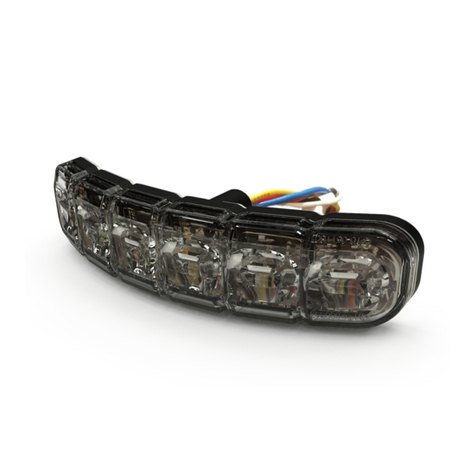
Ecco 37038AS Installation instructions

Installation & Operation
Instructions Narrowstik
WARNING!
Failure to install or use this product according to manufacturers recommendations may result in property
damage, serious bodily/personal injury, and/or death to you and those you are seeking to protect!
!
Do not install and/or operate this safety product unless you have read and understand the safety
information contained in this manual.
1. Proper installation combined with operator training in the use, care, and maintenance of emergency warning devices
are essential to ensure the safety of you and those you are trying to protect.
2. Exercise caution when working with live electrical connections.
3. This product must be properly grounded. Inadequate grounding and/or shorting of electrical connections can cause high
current arcing, which can cause personal injury and/or severe vehicle damage, including re.
4. Proper placement and installation are vital to the performance of this warning device. Install this product so that output
performance of the system is maximized and the controls are placed within convenient reach of the operator so that
s/he can operate the system without losing eye contact with the roadway.
5. It is the responsibility of the vehicle operator to ensure during use that all features of this product work correctly. In use,
the vehicle operator should ensure the projection of the warning signal is not blocked by vehicle components (i.e., open
trunks or compartment doors), people, vehicles, or other obstructions.
6. The use of this or any other warning device does not ensure all drivers can or will observe or react to a warning signal.
Never take the right-of-way for granted. It is your responsibility to be sure you can proceed safely before entering an
intersection, driving against trafc, responding at a high rate of speed, walking on or around trafc lanes.
7. This equipment is intended for use by authorized personnel only. The user is responsible for understanding and
obeying all laws regarding warning signal devices. Therefore, the user should check all applicable city, state, and federal laws and
regulations. The manufacturer assumes no liability for any loss resulting from the use of this warning device.
Page 1 of 6
IMPORTANT: Please be sure to check that the product is properly fused. Installing the 37038AS LED light without the appropriate fuse will void the warranty.
Product 37038AS
Extreme Voltage 11-30VDC
Nominal Voltage 12-24VDC
Peak Input Current 4 Amp
Output Power 24 W
Flash Paterns 32
Fuse (User supplied) 5A
Storage Temperature Range -40º ~ +90ºC
Weight 4.3 lb.
Specications:
Operating Environment:
Ambient Temperature: -10ºC to 50ºC
Relative Humidity: 10% to 85%, non-condensing

Page 2 of 6
Operation:
ON/OFF FLASH SWITCH: The 3 position rocker switch used to control the LED ash brightness/ off states.
CENTER LEFT/ SWITCH: The rocker switch to control LED from right to left.
CENTER RIGHT/ SWITCH: The rocker switch to control LED from left to right.
Note: Both CENTER switches in UP position puts unit in CENTER operation.
Mounting:
Mount the 37038AS LED light using the brackets supplied and user supplied mounting screws.
CAUTION: Check the chosen mounting location to ensure that the vehicle’s structure and material is adequate to support the
weight of your light.
ON/OFF PATTERN SELECT MODES:
DN= Turn the 2 position switch to off/Turn the 3 position switch to DOWN position.
UP= Turn the 2 position switch to on/Turn the 3 position switch to UP position.
X= Turn the 3 position switch to MIDDLE position.
※
The 3 position rocker switch in UP mode is in DIM state/ in DN mode is in BRIGHT state.
※ Touching the yellow wire to the black wire (ground) will change the ash patterns.
Switch
Position
Operation NOTE
ON/OFF
FLASH
CENTER
LEFT
CENTER
RIGHT
X
DN
DN
OFF
OFF
DN
DN
DN
FLASH (BRIGHT)
P1 P5 P9 P13 P17
P21 P25 P29
UP
DN
DN
FLASH (DIM)
DN
UP
DN
RIGHT SWEEP(BRIGHT)
P2 P6 P10
P14 P18 P22 P26
P30
UP
UP
DN
RIGHT SWEEP(DIM)
DN
DN
UP
LEFT SWEEP(BRIGHT)
P3 P7 P11 P15 P19 P23
P27
P31
UP
DN
UP
LEFT SWEEP(DIM)
DN
UP
UP
CENTER (BRIGHT)
P4 P8 P12 P16 P20
P24 P28 P32
UP
UP
UP
CENTER (DIM)
LAMP 8LAMP 1 LAMP 2 LAMP 3 LAMP 4 LAMP 5 LAMP 6 LAMP 7
Adjustment:
After the 37038AS light is securely installed, loosen the adjusting screws located on each end and tilt the light to the
desired angle. Then tighten the screws. Turn the LED light on and check the light from the front or rear of the vehicle,
through the window, to ensure that it is at the most desirable angle, and that the light is not impeded by any obstacles
and/or window tinting.

37038AS FLASH PATTERN CHART
LAMP 1 LAMP 2 LAMP 3 LAMP 4 LAMP 5 LAMP 6 LAMP 7 LAMP 8
P1: FLASH
L
AMP 1 LAMP 2 LAMP 3 LAMP 4 LAMP 5 LAMP 6 LAMP 7 LAMP 8
P2: RIGHT SWEEP
LAMP 1 LAMP 2 LAMP 3 LAMP 4 LAMP 5 LAMP 6 LAMP 7 LAMP 8
P3: LEFT SWEEP
LAMP 1 LAMP 2 LAMP 3 LAMP 4 LAMP 5 LAMP 6 LAMP 7 LAMP 8
P4: CENTER
L
AMP 1 LAMP 2 LAMP 3 LAMP 4 LAMP 5 LAMP 6 LAMP 7 LAMP 8
P5: FLASH
LAMP 1 LAMP 2 LAMP 3 LAMP 4 LAMP 5 LAMP 6 LAMP 7 LAMP 8
P6: RIGHT SWEEP
LAMP 1 LAMP 2 LAMP 3 LAMP 4 LAMP 5 LAMP 6 LAMP 7 LAMP 8
P8: CENTER
L
AMP 1 LAMP 2 LAMP 3 LAMP 4 LAMP 5 LAMP 6 LAMP 7 LAMP 8
P9: FLASH
LAMP 1 LAMP 2 LAMP 3 LAMP 4 LAMP 5 LAMP 6 LAMP 7 LAMP 8
P10: RIGHT SWEEP
LAMP 1 LAMP 2 LAMP 3 LAMP 4 LAMP 5 LAMP 6 LAMP 7 LAMP 8
P11: LEFT SWEEP
L
AMP 1 LAMP 2 LAMP 3 LAMP 4 LAMP 5 LAMP 6 LAMP 7 LAMP 8
P12: CENTER
LAMP 1 LAMP 2 LAMP 3 LAMP 4 LAMP 5 LAMP 6 LAMP 7 LAMP 8
P13: FLASH
LAMP 1 LAMP 2 LAMP 3 LAMP 4 LAMP 5 LAMP 6 LAMP 7 LAMP 8
P7: LEFT SWEEP
Page 3 of 6

Page 4 of 6
LAMP 1 LAMP 2 LAMP 3 LAMP 4 LAMP 5 LAMP 6 LAMP 7 LAMP 8
P14: RIGHT SWEEP
LAMP 1 LAMP 2 LAMP 3 LAMP 4 LAMP 5 LAMP 6 LAMP 7 LAMP 8
P15: LEFT SWEEP
LAMP 1 LAMP 2 LAMP 3 LAMP 4 LAMP 5 LAMP 6 LAMP 7 LAMP 8
P16: CENTER
LAMP 1 LAMP 2 LAMP 3 LAMP 4 LAMP 5 LAMP 6 LAMP 7 LAMP 8
P17: FLASH
LAMP 1 LAMP 2 LAMP 3 LAMP 4 LAMP 5 LAMP 6 LAMP 7 LAMP 8
P18: RIGHT SWEEP
LAMP 1 LAMP 2 LAMP 3 LAMP 4 LAMP 5 LAMP 6 LAMP 7 LAMP 8
P19: LEFT SWEEP
LAMP 1 LAMP 2 LAMP 3 LAMP 4 LAMP 5 LAMP 6 LAMP 7 LAMP 8
P20: CENTER
LAMP 1 LAMP 2 LAMP 3 LAMP 4 LAMP 5 LAMP 6 LAMP 7 LAMP 8
P21: FLASH
LAMP 1 LAMP 2 LAMP 3 LAMP 4 LAMP 5 LAMP 6 LAMP 7 LAMP 8
P22: RIGHT SWEEP
L
AMP 1 LAMP 2 LAMP 3 LAMP 4 LAMP 5 LAMP 6 LAMP 7 LAMP 8
P23: LEFT SWEEP
LAMP 1 LAMP 2 LAMP 3 LAMP 4 LAMP 5 LAMP 6 LAMP 7 LAMP 8
P24: CENTER
LAMP 1 LAMP 2 LAMP 3 LAMP 4 LAMP 5 LAMP 6 LAMP 7 LAMP 8
P25: FLASH
LAMP 1 LAMP 2 LAMP 3 LAMP 4 LAMP 5 LAMP 6 LAMP 7 LAMP 8
P26: RIGHT SWEEP

Page 5 of 6
L
AMP 1 LAMP 2 LAMP 3 LAMP 4 LAMP 5 LAMP 6 LAMP 7 LAMP 8
P27: LEFT SWEEP
L
AMP 1 LAMP 2 LAMP 3 LAMP 4 LAMP 5 LAMP 6 LAMP 7 LAMP 8
P28: CENTER
LAMP 1 LAMP 2 LAMP 3 LAMP 4 LAMP 5 LAMP 6 LAMP 7 LAMP 8
P29: FLASH
LAMP 1 LAMP 2 LAMP 3 LAMP 4 LAMP 5 LAMP 6 LAMP 7 LAMP 8
P30: RIGHT SWEEP
LAMP 1 LAMP 2 LAMP 3 LAMP 4 LAMP 5 LAMP 6 LAMP 7 LAMP 8
P31: LEFT SWEEP
LAMP 1 LAMP 2 LAMP 3 LAMP 4 LAMP 5 LAMP 6 LAMP 7 LAMP 8
P32: CENTER
Flash patterns P30 and P31 are SAE J595 compliant.

Troubleshooting:
The 37038AS has been factory tested and approved. If the light fails to work, check the following:
1. Press the Function Switch (User Supplied) to be sure the “Off” pattern is not selected.
2. Remove the fuse from the vehicle fuse box and check to see if it has blown.
Manufacturer Limited Warranty and Limitation of Liability:
Manufacturer warrants that on the date of purchase, this product will conform to Manufacturer’s specications for this product
(which are available from the Manufacturer upon request). This Limited Warranty extends for thirty-six (36) months from the
date of purchase.
DAMAGE TO PARTS OR PRODUCTS RESULTING FROM TAMPERING, ACCIDENT, ABUSE, MISUSE, NEGLIGENCE, UN-
APPROVED MODIFICATIONS, FIRE OR OTHER HAZARD; IMPROPER INSTALLATION OR OPERATION; OR NOT BEING
MAINTAINED IN ACCORDANCE WITH THE MAINTENANCE PROCEDURES SET FORTH IN MANUFACTURER’S INSTAL-
LATION AND OPERATING INSTRUCTIONS VOIDS THIS LIMITED WARRANTY.
Exclusion of Other Warranties:
MANUFACTURER MAKES NO OTHER WARRANTIES, EXPRESSED OR IMPLIED. THE IMPLIED WARRANTIES FOR
MERCHANTABILITY, QUALITY OR FITNESS FOR A PARTICULAR PURPOSE, OR ARISING FROM A COURSE OF DEAL-
ING, USAGE OR TRADE PRACTICE ARE HEREBY EXCLUDED AND SHALL NOT APPLY TO THE PRODUCT AND ARE
HEREBY DISCLAIMED, EXCEPT TO THE EXTENT PROHIBITED BY APPLICABLE LAW. ORAL STATEMENTS OR REP-
RESENTATIONS ABOUT THE PRODUCT DO NOT CONSTITUTE WARRANTIES.
Remedies and Limitation of Liability:
MANUFACTURER’S SOLE LIABILITY AND BUYER’S EXCLUSIVE REMEDY IN CONTRACT, TORT (INCLUDING NEG-
LIGENCE), OR UNDER ANY OTHER THEORY AGAINST MANUFACTURER REGARDING THE PRODUCT AND ITS
USE SHALL BE, AT MANUFACTURER’S DISCRETION, THE REPLACEMENT OR REPAIR OF THE PRODUCT, OR THE
REFUND OF THE PURCHASE PRICE PAID BY BUYER FOR NON-CONFORMING PRODUCT. IN NO EVENT SHALL
MANUFACTURER’S LIABILITY ARISING OUT OF THIS LIMITED WARRANTY OR ANY OTHER CLAIM RELATED TO THE
MANUFACTURER’S PRODUCTS EXCEED THE AMOUNT PAID FOR THE PRODUCT BY BUYER AT THE TIME OF THE
ORIGINAL PURCHASE. IN NO EVENT SHALL MANUFACTURER BE LIABLE FOR LOST PROFITS, THE COST OF SUB-
STITUTE EQUIPMENT OR LABOR, PROPERTY DAMAGE, OR OTHER SPECIAL, CONSEQUENTIAL, OR INCIDENTAL
DAMAGES BASED UPON ANY CLAIM FOR BREACH OF CONTRACT, IMPROPER INSTALLATION, NEGLIGENCE, OR
OTHER CLAIM, EVEN IF MANUFACTURER OR A MANUFACTURER’S REPRESENTATIVE HAS BEEN ADVISED OF THE
POSSIBILITY OF SUCH DAMAGES. MANUFACTURER SHALL HAVE NO FURTHER OBLIGATION OR LIABILITY WITH
RESPECT TO THE PRODUCT OR ITS SALE, OPERATION AND USE, AND MANUFACTURER NEITHER ASSUMES NOR
AUTHORIZES THE ASSUMPTION OF ANY OTHER OBLIGATION OR LIABILITY IN CONNECTION WITH SUCH PRODUCT.
This Limited Warranty denes specic legal rights. You may have other legal rights which vary from jurisdiction to jurisdiction.
Some jurisdictions do not allow the exclusion or limitation of incidental or consequential damages.
833 West Diamond St
Boise, Idaho 83705
Customer Service
USA 800-635-5900
UK +44 (0)113 237 5340
AUS +61 (0)3 63322444
www.eccogroup.com
920-0446-00 Rev. A Page 6 of 6
Table of contents
Other Ecco Light Fixture manuals
Popular Light Fixture manuals by other brands

Eternal Lighting
Eternal Lighting Mini60 Spot user guide

Denver
Denver LCO-551 user manual

EuroLite
EuroLite BSLC-10 user manual

Schrack Technik
Schrack Technik Arktur Square LED installation instructions

Philips
Philips 6913087PH Instruction leaflet

Cooper Lighting
Cooper Lighting Quiet Ceiling QCT-1775BK Specification sheet