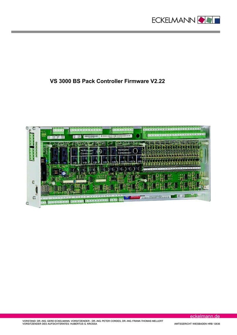
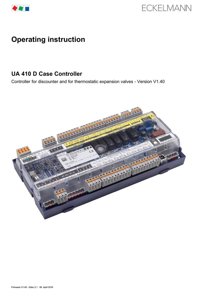
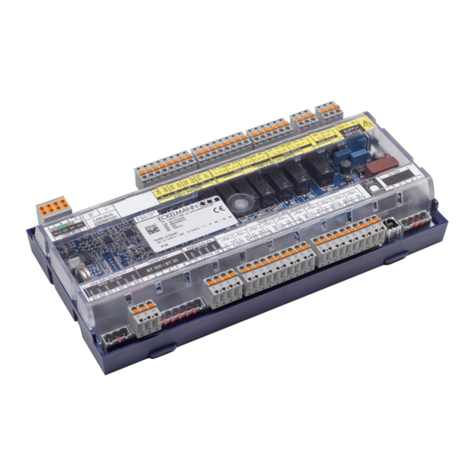
ECKELMANN UA 410 L Case Controller User manual

Firmware V1.50 - Doku 2.0 06. April 2016
Operating instruction
UA 410 L Case Controller
Temperature Data Logging Controller - Version V1.50

Firmware V1.50 - Doku 2.0 06. April 2016
Eckelmann Gruppe
Eckelmann AG
Business Unit Refrigeration and Building Management Systems
Berliner Straße 161
65205 Wiesbaden, Germany
Telephone +49 611 7103-0
Fax +49 611 7103-133
www.eckelmann.de
Board of Directors:
Dr.-Ing. Gerd Eckelmann (Vorsitzender), Dipl.-Ing. Peter Frankenbach, Dr.-Ing. Frank-Thomas Mellert,
Dr.-Ing. Marco Münchhof, Dr.-Ing. Frank Uhlemann
Chairman of the supervisory board:
Hubertus G. Krossa
Registration court / registration number
District court Wiesbaden, Germany
HRB 12636
Before commissioning and use, please check that this is the latest version of the document.
With the publication of a new version of the documentation, all previous versions lose their validity.
Errors and technical modifications are expressly reserved.
The current operating manual and information such as data sheets, more detailed documentation and FAQs are
available for you on-line in E°EDP (Eckelmann ° Electronic Documentation Platform) at
www.eckelmann.de/elds
You reach all relevant documents for this component directly using the QR code:
Information on safety and connection instructions
are described in detail in chapter 1 ”Industrial safety notes”.
All rights to any use whatever, utilisation, further development, forwarding and creation of copies remain with
the Eckelmann AG company.
In particular, neither the contract partners of Eckelmann AG nor other users have the right to distribute or mar
ket the IT programs/program parts or modified or edited versions without express written permission. To some
extent, names of products/goods or designations are protected for the respective manufacturer (registered
trademarks etc.); in any case, no guarantee is assumed for their free availability/permission to use them. The
information provided in the description is given independently of any existing patent protection or other third-
party rights.

i
Firmware V1.50 - Doku 2.0 06. April 2016
Conventions 1.....................................................................
Explanation of 'General Instructions' 1.................................................
Explanation of 'Safety Instructions and Hazard Warnings' 1..............................
Warning Signs and Symbols Employed 2..............................................
1 Safety instructions 3.....................................................
1.1 Disclaimer in the event of non-compliance 4.................................
1.2 Personnel requirements, requirements on staff 4.............................
1.3 Intended use 5...........................................................
1.4 BGV A3 - Five safety rules 5...............................................
1.5 Electrostatic sensitive devices (ESDs) 6.....................................
1.5.1 ESD - Rules for handling and working 6.....................................
1.6 Abbreviations used 6......................................................
2 System Design of UA 410 L 7.............................................
2.1 Application 7.............................................................
2.2 Hardware 8..............................................................
2.3 New features compared to previous versions 9...............................
3 Application of UA 410 L 11................................................
3.1 Versions 11...............................................................
3.2 Controller type 12..........................................................
3.2.1 Version update 12.........................................................
4 Function of UA 410 L 13...................................................
4.1 Selection of the temperature sensors 13......................................
4.2 Required and optional sensors 14...........................................
4.3 Controller function 14......................................................
4.3.1 Cooling (solenoid valve) 14.................................................
4.3.1.1 Temperature control (with recording) 15......................................
4.3.1.2 Emergency operation 15....................................................
4.3.1.3 Temperature recording 16..................................................
4.3.2 Defrosting 17..............................................................
4.3.3 Monitoring 18.............................................................
4.3.4 Archiving operating data 19.................................................
4.3.4.1 Temperature recording to EU Regulation 37/2005 19...........................
4.3.4.2 Temperature recording to EU Regulation DIN EN 12830 19.....................
4.3.5 Real time clock 21.........................................................

ii Firmware V1.50 - Doku 2.0 06. April 2016
4.4 Temperature display BT 30 22..............................................
4.4.1 Offset for temperature display 22............................................
4.4.2 Connecting BT 30 Temperature Display 22...................................
5 Installation and Startup of UA 410 L 25.....................................
5.1 Installation 25.............................................................
5.1.1 DIN rail mounting of the Temperature Data Logging Controller 25................
5.1.1.1 Mounting on the DIN rail 26.................................................
5.1.1.2 Disassembling from the DIN rail 27...........................................
5.1.2 Handling of the spring terminals 28..........................................
5.2 Basic configuration 29......................................................
5.3 Setting CAN bus address 30................................................
5.4 Setting the controller type 31................................................
5.5 Terminal assignment for 230 V AC power supply 32............................
5.5.1 Status LEDs 33............................................................
5.6 Basic configuration of the controller 34.......................................
5.6.1 Naming of the controller 37.................................................
5.7 Restart - restart of the controller 37..........................................
5.8 First start / reset controller to factory settings 37...............................
5.9 Maintenance and battery replacement 38.....................................
5.10 Firmware Update 40.......................................................
5.10.1 Firmware Update requirements 40...........................................
5.10.2 Uploading the firmware update 43...........................................
5.10.3 Rectification of driver problems 45...........................................
6 Pin and Terminal Assignments of UA 410 L 47..............................
6.1 Terminal diagram 47.......................................................
6.2 Terminal assignment of the 230 V AC power supply 48.........................
6.3 Terminal assignment of the 230 V AC relay outputs 49.........................
6.4 Mode of operation of the relay and transistor outputs 50........................
6.5 Terminal assignment of the 230 V AC digital inputs 50.........................
6.6 Terminal assignment of the 0..10 V analogue outputs 51.......................
6.7 Terminal assignment of the CAN bus 52......................................
6.8 Terminal assignment of the 24 V DC transistor outputs 53......................
6.9 Terminal assignment of the DISPLAY interface 54.............................
6.10 Terminal assignment of the 4..20 mA analogue inputs 54.......................
6.11 Terminal assignment of the analogue inputs of temperature sensors 55..........

iii
Firmware V1.50 - Doku 2.0 06. April 2016
6.12 Terminal assignment of the USB interface 56.................................
6.13 Terminal assignment of the CI 320/TTY interface 56...........................
7 Operation of UA 410 L 57..................................................
7.1 Operation possibilities 57...................................................
7.2 Local operation with a BT 300 x operator interface 58..........................
7.2.1 Lock-down of the setpoint change 58........................................
7.3 Remote control via a terminal 59.............................................
7.3.1 Menus and operating screens 60............................................
7.3.2 Calling the controller menu via remote control 62..............................
7.3.2.1 System Centre CI 4x00 63..................................................
7.3.2.2 Store computer CI 3x00 / operator terminal AL 300 63..........................
7.3.3 Deactivating the input lock-down 64..........................................
7.3.3.1 System centre CI 4x00 64..................................................
7.3.3.2 Store computer CI 3x00 / operator terminal AL 300 64..........................
7.3.4 Activating service mode 65.................................................
7.3.4.1 System centre CI 4x00 65..................................................
7.3.4.2 Store computer CI 3x00 65.................................................
8 Menu Structure of UA 410 L 67............................................
8.1 Controller type UA 410 L – Menu tree (Rx.1 to Rx.0) 67........................
8.2 Menu 0 Main menu 68.....................................................
8.3 Menu 1 Actual Value 68....................................................
8.4 Menu 2 Setpoints 69.......................................................
8.5 Menu 3 Clock 69..........................................................
8.6 Menu 4 Messages 70......................................................
8.7 Menu 5 Archive 71.........................................................
8.8 Menu 6 Configuration 72...................................................
9 Decommissioning and disposal 75.........................................
9.1 Decommissioning / Demounting 75..........................................
9.2 Disposal 75...............................................................

iv Firmware V1.50 - Doku 2.0 06. April 2016
10 Alarms and Messages of UA 410 L 77......................................
10.1 Alarm signaling and monitoring 78...........................................
10.1.1 High or low temperature alarm 78............................................
10.1.2 Disabling high or low temperature alarm 78...................................
10.1.3 No defrost alarm 78........................................................
10.1.4 Sensor break alarm 79.....................................................
10.1.5 Hardware fault alarm 79....................................................
10.1.6 Alarm routes 79...........................................................
10.2 Messages 79..............................................................
10.2.1 Transient alarms and messages 80..........................................
10.2.2 Message log 80...........................................................
11 Specifications of UA 410 L 81.............................................
11.1 Electrical data 81..........................................................
11.2 Mechanical data of the controller 84..........................................
11.3 Mechanical data of the temperature sensor L243 / 5K3A1 84...................
12 Order numbers and accessories of UA 410 L 85............................
12.1 Case Controller 85.........................................................
12.2 Accessories 85............................................................

1
Firmware V1.50 - Doku 2.0 06. April 2016
Conventions
Explanation of 'General Instructions'
A general instruction is composed of two elements:
1. A pictogram of a hand at the side of the page as well as
2. The actual text:
For example:
Further information on the device's degree of protection is contained in the chapter ”Technical Data”.
Explanation of 'Safety Instructions and Hazard Warnings'
Safety instructions or hazard warnings are composed of four elements:
1. The pictogram (warning sign / symbol) at the edge of the page.
2. A short, concise description of the danger.
3. A description of the possible consequences.
4. A catalogue with prevention measures.
For example:
Warning - hazardous electrical voltage!
Danger of electric shock! BEFORE and AFTER connection it
must checked that the 230 V AC relay outputs are off load!
On the following pages the warning signs and symbols employed for
the safety instructions and hazard warnings in this documentation are described in more detail.

2Firmware V1.50 - Doku 2.0 06. April 2016
Warning Signs and Symbols Employed
Explanation of the warning signs and symbols employed for the safety instructions and hazard warnings in this
documentation:
SAttention symbol - general hazard warning
1. Hazard warning
The attention symbol indicates all safety instructions in this operating and service manual, which, if not
observed, could result in danger to life and limb. Carefully comply with the work safety instructions and
proceed with special caution in these cases.
2. Attention
The attention symbol highlights guidelines and regulations, instructions and correct working procedures
that must be carefully observed in order to prevent damage to or destruction of E*LDS components or a
malfunctioning (for example to avoid damage to goods).
Failure to observe the attention symbol can result in personal injury (in extreme cases serious injuries or
death) and/or material damage!
SVoltage symbol - warns of hazardous electrical voltage
This work safety symbol warns of danger from a hazardous electrical voltage,
with potential consequences such as serious injury or death.
SESD symbol - warns of electrostatic sensitive components and assemblies
This symbol indicates electrostatic sensitive components and assemblies,
for details see chapter 1.5.
SNote symbol
The note symbol highlights practice tips and other useful information contained in this
operating and service manual.
SBattery disposal symbol
Never dispose of this product with other household waste. Please inform yourself of the local regula
tions for the separate disposal of electrical and electronic products. The correct disposal of your old
equipment will protect people and the environment from possible negative effects.
You will find further information in the chapter ”Decommissioning and Disposal”.

Safety instructions
3
Firmware V1.50 - Doku 2.0 06. April 2016
1 Safety instructions
The safety regulations, codes and notes contained in this section must definitely be observed and
complied with at all times. During repairs on the entire E*LDS system, the accident prevention regu
lations and general safety instructions must be observed. Important information (safety instructions
and hazard warnings) are indicated by corresponding symbols (see page 1 of the chapter ”Conven
tions”).
Follow these instructions in order to prevent accidents and danger to life and limb, as well as dam
age to the E*LDS system.
Warning - hazardous electrical voltage!
Danger of electric shock! Beware of external voltage at the digital inputs and outputs!
All device connections/plugs are only to be plugged in, unplugged and/or wired when off load.
SThis manual is an integral part of the equipment. It must be kept in the proximity of the equipment and must
be stored for future use, so that it can be referred to when necessary. To avoid operating errors, the operation
instructions must always be kept available for operating and maintenance staff, see Chapter 1.2.
SFor safety reasons, the equipment must not be used for any application other than described in the manual
i.e. only for the intended use, see Chapter 1.3.
SBefore using the equipment, always check that its limits are suitable for the intended application.
SThe equipment must be installed in an electrically shielded area within the refrigerated display case or con
trol cabinet.
SCheck that the electric power supply is correct for the equipment before connecting it to power.
SWhen using uncoded plug connectors, it is possible to connect them so that there is a danger to life and limb!
If this cannot be ruled out, coded plug connectors must be used.
SSpecified ambient conditions (e.g. humidity and temperature limits) must be observed and complied with in
order to avoid malfunctioning (see Section “Specifications”).
SCheck correct wiring of the connections before switching on power to the equipment.
SNever operate the equipment without its casing. Before opening the casing the equipment must be switched to
zero potential.
SNote and observe maximum load on relay contacts (see Section “Specifications”).
SContact the supplier in any malfunction.
SNote that all leads running to and from the controller- especially those of the CAN bus - must be shielded and
installed sufficiently clear of other leads carrying live power. Doing so will avoid faulty measurements and will
protect the equipment from external interference via the analog inputs.
Parallel connection of RC elements is recommended for applications in a critical environment.
1. According to experience, error message transmission is not yet fully functional during commis
sioning (no telephone line laid etc.) In such cases it is urgently recommended to monitor the con
troller via the CAN bus using a system centre, a store computer or an operator terminal, and enable
error message transmission e.g. using a GSM modem via a mobile telephone network. In stand
alone operation, or as an alternative to monitoring with the system centre / store computer / operator
terminal, an alarm contact on the controller must be used in order to realise error message transmis
sion via a telephone network.
2. In the interests of fire prevention, allowance should be made at the time of planning the system
for a suitable shutdown device designed to operate in the event of excessive temperature on the
defrost heater (high-temperature cutout).
For further information on the CAN bus, see the operation instructions
”Basic and General Safety and Connection Instructions”.

Safety instructions
4Firmware V1.50 - Doku 2.0 06. April 2016
Work on electrical equipment may only be undertaken by authorized and duly trained personnel
(as defined by DIN/VDE 0105 and IEC364) with full observance of the currently valid regulations
contained in the following:
- VDE Regulations
- Local safety codes
- Intended use see chapter 1.3
- BGV A3 - Five Safety Rules see chapter 1.4
- ESD precautions and rules see chapter 1.5.
- Operating instructions
1.1 Disclaimer in the event of non-compliance
These operating instructions contain information on the commissioning, function, operation and maintenance of
the controls and of the associated components.
Observance of these operating instructions is a prerequisite for safe and trouble-free operation.
1.2 Personnel requirements, requirements on staff
Special skills are required for project planning, programming, assembly, commissioning and maintenance work.
This work may be performed by qualified and specially trained staff.
The staff involved in installation, commissioning and maintenance must have received the special training
needed for them to work on the unit and on the automation system.
The project planning and programming staff must be familiar with the safety concepts involved in automation
technology.
Expertise is a requirement for any work on electrical systems. Work on electrical installations may only be per
formed by trained electrical specialists (or may only be performed when directed or supervised by them). The
applicable regulations (e.g. DIN EN 60204, EN 50178, BGV A3, and DIN VDE 0100/0113) must be followed.
The operating staff who deal with the unit/machine and the controls must be correspondingly trained and familiar
with the operating instructions.

Safety instructions
5
Firmware V1.50 - Doku 2.0 06. April 2016
1.3 Intended use
This control system may only be used for the purpose for which it is intended:
The UA 410 L control system has been designed for use as a data logging controller in commercial and indus
trial refrigeration systems with the intended functional scope as described in these operating instructions, and it
is to be used under the environmental conditions in these instructions.
Follow the safety instructions, as well as the instructions on installation, commissioning, operation and mainte
nance. Only THEN should you start commissioning or operating the machine/system.
The safety and function of the machine/unit is only assured in the use for which it has been intended.
Never use the machine/unit, its components, assemblies or parts of it for a different purpose.
The installation may be only operated for the first time when the entire unit has been shown to conform
to the EC Directives.
1.4 BGV A3 - Five safety rules
The following rules must be strictly observed:
1. Disconnect electric power: Disconnect power at all connections of the entire installation on which
work is to be carried out.
Warning - hazardous electrical voltage!
Beware of possible external power supplies! BEFORE and AFTER connection it must be checked
that the controller is off load! All device connections/plugs are only to be plugged in, unplugged and/
or wired when off load.
2. Secure against reconnection of power: Tag the disconnected equipment with the following information:
‐ What has been disconnected from power
‐ Why it has been disconnected
‐ Name of person who disconnected power
‐ Use a suitable lock-out (e.g. padlock) to prevent reconnection of power.
3. Make sure that power is off (authorized and duly trained personnel only):
‐ Check with voltmeter immediately before use.
‐ Check that power is off on all connections at the disconnection point.
‐ Check that power is off on all connections at the place of work.
4. Ground and short circuit: Ground and then short circuit all electrical parts at the place of work.
5. Cover or bar off adjacent power-carrying parts: Any equipment carrying power adjacent to the work area
must be covered by suitable means (e.g. insulating cloths or panels).

Safety instructions
6Firmware V1.50 - Doku 2.0 06. April 2016
1.5 Electrostatic sensitive devices (ESDs)
Electronic components and assemblies (e.g. printed circuit boards) are vulnerable to electrostatic
discharge. Regulations for handling and working with electrostatic sensitive devices must definitely
be observed and complied with, see also section 1.5.1!
All electrostatic sensitive devices (ESDs) are identified by the warning sign illustrated. Electrostatic discharge is
caused by friction of insulating materials (e.g. floor coverings, synthetic fiber clothing, etc.).
Even slight charges can cause components to be damaged or destroyed. Damage cannot always be ascer
tained directly and it may take time for the component to actually fail in operation.
1.5.1 ESD - Rules for handling and working
Transport and store ESDs only in the protective packaging provided.
Avoid materials that may produce electrostatic discharge, for example
‐ Plastic containers and table tops
‐ Synthetic fiber clothing
‐ Plastic-soled shoes
‐ Plastic file covers
‐ Styrofoam packaging
‐ Computer monitors, etc.
Preferably wear the following:
‐ Cotton work clothes
‐ ESD shoes with conductive soles or leather soles
Use the following:
‐ Conductive flooring
‐ ESD workstations equipped with suitable tools (grounded soldering guns, antistatic wrist straps, etc.)
‐ Conductive ESD bags, conductive plastic containers, IC tubes or cartons lined with conductive foam
‐ Containers and worktops made of wood, metal or conductive plastics or paper bags
1.6 Abbreviations used
DIN Deutsches Institut für Normung e. V.
EGB Elektrostatisch Gefährdete Bauelemente oder Baugruppen
ESD Electro-static discharge (Electro Sensitive Devices)
VDE Verband der Elektrotechnik Elektronik Informationstechnik e.V.
IEC International Electric Committee
BGV Employer’s Liability Association regulations for health and safety in the workplace

System Design of UA 410 L
7
Firmware V1.50 - Doku 2.0 06. April 2016
2 System Design of UA 410 L
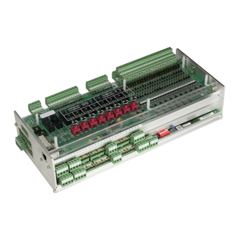
Figure: UA 410 L AC - full configuration
2.1 Application
The UA 410 L AC temperature recording controller is based on the UA 400 hardware and has been developed
for use as a temperature recording controller of up to 10 temperature measurement points.
In addition to the recording function, it is also possible to control and defrost the first five sensors, so that a total
of five refrigeration points can be regulated independently of each other.
The UA 410 L AC can be used for temperature recording in accordance with the EU DIN EN 12830 Directive.
Here, the controller is integrated in the E*LDS system but it also offers the redundant temperature recording re
quired by the standard.
In order to fully utilise its performance features the controller is typically connected to the CAN bus, through
which it communicates with further control and monitoring components across the entire network. Via the CAN
bus an intelligent data exchange is carried out with the following system components:
- System Centre /
Store computer: Archiving of the operating data as well as alarm and message management,
Connection to E*LDSWin for analysis, configuration and evaluation
- Pack controller: Data exchange between the E*LDS components
- Refrigeration point
controller: Data recording between the E*LDS components
A BT 300 x Operator Interface and one to four BT 30 Temperature Displays can be connected to the controller
when required. Electrical connections are described in Section – Pin and Terminal Assignments.

System Design of UA 410 L
8Firmware V1.50 - Doku 2.0 06. April 2016
2.2 Hardware
The temperature recording controller is housed in a plastic casing for DIN rail mounting and does not require
any further optional expansion modules. Up to 99 case controllers can be used within the E*LDS system. As
required, a BT 300 x Operator Interface and up to 4 BT 30 Temperature Displays can be connected. For a
firmware update, the controller can be connected to a laptop or PC via the USB interface. The application range
of the temperature recording controller is described in more detail in chapter 3.2.
The following diagram illustrates the system architecture of the UA 410 L AC temperature recording controller
(complete):
CAN bus
Digital outputs:
4 x normal open contact
3 x two-way-contacts
2 x 24 V DC / 50 mA
4 x
Analog inputs:
230 V AC
(1x)
BT 300
ESC
RESET
BT 30
(0..4x)
Case Controllers
(1..99)
Digital inputs:
2 x 4..20 mA
2-wire-NTC-
temperature sensors
2 x Analog outputs:
0..10 V
USB
ZNR. 115 130 E1
MODEESC
PRIO 1
PRIO 2
,
0
ALARM
RESET
V4.24
AL 300
CI 3000
CI 3100
CI 4x00
Ports:
CAN bus: Communication in E*LDS-System, new version
DISPLAY: Connection for BT 300x Operator Interface and
up to four BT 30 Temperature Displays
CI 320: Communication with LDSWin software / Connection to the legacy system CI 320
USB: For conducting a firmware update
Inputs/outputs
4 digital inputs 230 V AC, floating
10 analog inputs Connection for two-wire NTC temperature sensors
2 x analogue inputs 4..20 mA - currently without function
Outputs
3 relay output 230 V AC / 6 A (changeover)
4 relay outputs 230 V AC / 6 A (N.O.)
2 transistor outputs 24 V DC / 50 mA
2 x analogue outputs 0..10 V DC - currently without function

System Design of UA 410 L
9
Firmware V1.50 - Doku 2.0 06. April 2016
Real-time clock
Battery-backed, lithium cell
For precise details of the UA 410 L AC see chapter 3.1. The connection and terminal configurations
are described in the chapter Connection and Terminal Configuration.
2.3 New features compared to previous versions
Version 1.50
SNew hardware platform UA 410 L
- blue main board
- grey, coded mating connector with spring terminals, see chapter 5.1.2
- two-row CAN bus spring terminal for easier wiring
Version 1.50
SNew hardware platform UA 410 L – blue case with compact dimensions, see chapter 11.2.
SCoded connectors

System Design of UA 410 L
10 Firmware V1.50 - Doku 2.0 06. April 2016
Version 1.50
SNew hardware platform UA 410 L - for DIN rail mounting
SOptimised labelling strip
SDifferences in the complete hardware (UA 410 L AC, see photo) compared to UA 300 L AC:
- 2 analogue inputs 4..20 mA Currently reserve for future applications
- 2 analogue outputs 0.. 10 V Currently reserve for future applications
- Fourth digital input Currently reserve for future applications
- USB interface For firmware update
SAdjustment and implementation on the basis of the new hardware platform:
The essential functions of the UA 300 L, its controller types and their functions, are retained in the UA 410 L.
SThe UA 410 L AC is the successor (replacement controller) to the UA 300 L AC, CC

Application of UA 410 L
11
Firmware V1.50 - Doku 2.0 06. April 2016
3 Application of UA 410 L
3.1 Versions
The UA 410 L is only available in the AC variant and has the following features:
UA 410 L AC
For DIN rail mounting F
For integration in the CAN bus of the E*LDS system F
Replacement controller for UA 300 L F
Replacement controller for the LDS1 system
(connection to the LDS1 system proceeds via the CI320 interface)
F
Suitable for stand alone operation F
With integrated real-time clock (lithium cell power reserve) F
With integrated archive memory for data recording F
2 analogue inputs 4..20 mA (currently without function) F
2 analogue outputs 0..10 V (currently without function) F
Abbreviations used
SAC stands for All in one and Cabinet/DIN rail mounting
(All = with CAN bus and real-time clock, i.e. C = cabinet mounting).

Application of UA 410 L
12 Firmware V1.50 - Doku 2.0 06. April 2016
3.2 Controller type
Ttemperature recording controller UA 410 L Case Controller:
Controller type Application
UA 410 L Temperature Data Logging Controller for maximum 10 temperature sensors
(with the option of on-off control/defrosting of five independent refrigeration points for the first five sensors).
For definition of the basic control behaviour, only one controller type can always be selected that is set using the
DIP switch S3. Only the controller type "UA 410 L" is available for the UA 410 L:
Set controller type DIP switchS3
Position of Coding Switch 1 to 8
12 3 4 5 6 7 8
UA 410 L OFF OFF OFF OFF OFF OFF OFF OFF
Operation of the controller with a unsupported DIP switch setting is not allowed. In the case of any
setting of coding switch combinations that are not present in the list, UA 410 L is automatically ap
plied as controller type and an alarm signal is created.
In the event of change of the controller type, all parameters are reset to their factory settings.
For further information, see chapter 5.4 - Controller type setting.
Selection of controller type defines the controller properties and basic controller settings.
The UA410 L Temperature Data Logging Controller can be operated by:
‐ Host computer e.g. via network / modem with connection to the system centre / store computer,
‐ the system centre, a store computer or an operator terminal,
‐ a local operator interface BT 300 via the DISPLAY interface on the controller or
‐ a notebook (PC) with the PC-software LDSWin connected via USB.
3.2.1 Version update
The case controller is supplied with the current firmware, ready for operation. Future software versions can be
loaded into the case controller as required by means of a firmware update, and thus updated.
Danger data loss! In some cases a change of firmware version can lead to the loss of all the set
points in the case controller.
As a precaution, the settings must be backed up by saving them to the LDSWin PC software,
prior to the update. After the firmware update the backup settings can be reloaded into the controller
from LDSWin.
A software update is only to be carried out by trained staff or factory-side by the manufacturer.
More details on firmware updates can be found in chapter 5.10.

Function of UA 410 L
13
Firmware V1.50 - Doku 2.0 06. April 2016
4 Function of UA 410 L
Parameters mentioned in this section are described in the Menu Structure section. It will normally
not be necessary to change the default settings of these parameters. Parameters that do not allow
changing are termed fixed parameters below.
4.1 Selection of the temperature sensors
The case/coldroom controller uses two-wire NTC temperature sensors to perform control.
All sensors connected must be the same type and parameters are not set separately for the sensors. The type
of sensor used can be defined by the Sensor Type parameter (Menu 6-2-5).
The NTC following sensor types are usable:
L243 (K243) Temperature range -50°C to 50°C; Type K243 sensor can be used in place
of type L243. Characteristics of these two sensors are identical.
K277 Temperature range -50 to 50°C
5K3A1 Temperature range 0 to 100°C
For information on the dimensions see chapter 11.3.
Detaillierte Informationen zu den Temperaturfühlern sind dem Datenblatt “Temperaturfühler” zu entnehmen.
Detailed information on the temperature sensors are contained in the data sheet “temperature sensors”.
All due care must be exercised when installing temperature sensors. Sensor leads need not be
shielded when installed exclusively within the refrigerated display case to be controlled and when
interference is not to be expected (for example from power wires running parallel to the leads. Other
wise suitable precautions must be taken to protect the sensor leads from external interference.
An offset can be independently applied to the temperature sensors, which is effective for display and control
functions, see Section 4.4.1.

Function of UA 410 L
14 Firmware V1.50 - Doku 2.0 06. April 2016
4.2 Required and optional sensors
On the standard UA 400 controllers the Sensor Scan function determines the number of sensors connected.
This enables sensors that are not connected to be removed from sensor break monitoring.
However, the following procedure is required with the UA 410 L Temperature Data Logging Controller:
If specific sensors are deactivated for the alarm signalling, the sensor priority must be configured accordingly.
The priority of each sensor can be set separately to ”0” (message) or ”-” (alarm suppressed) when no alarm is to
be signalled on the Temperature Data Logging Controller.
In addition to the sensors that should be monitored, the respective alarm priorities in the UA 410 L should also
be set to the values 0 (message) or 1..2 (alarm signal).
A sensor is recognised as connected in LDSWin (PC software) when its priority is set to 0 .. 2. It is
considered unused within LDSWin (no message/alarm/recording), when its priority is set to --.
Required and optional sensors are listed below:
Controller type Sensors necessary Optional sensors
(advanced functions e.g. for control, see
chapter 4.3.1)
UA 410 L None Rx.1 Rx.2 Rx.3 Rx.4 Rx.5
Rx.6 Rx.7 Rx.8 Rx.9 Rx.0
Sensor break alarm
Alarm only takes place for sensors set to a sensor alarm priority of 1 or higher. An alert is generated when sen
sor alarm priority is set to 0 and no alarm or message is generated when sensor alarm priority is set to ”-”.
This approach is different from that used with other case/coldroom controllers, on which sensor
break alarm can be set by sensor scan.
4.3 Controller function
The sections following describe the various functions of the UA 410 L for control and temperature recording of
refrigeration points.
4.3.1 Cooling (solenoid valve)
On-off control
Control is made by one temperature sensor (the first five temperature sensors Rx.1 .. Rx.5 only). The cooling
relay de-energizes when temperature reaches the setpoint (switch-off value, Menu 2) on the respective temper
ature sensor. The cooling relay re-energizes with the set hysteresis.
Table of contents
Other ECKELMANN Controllers manuals
ECKELMANN
ECKELMANN UA 410 L User manual
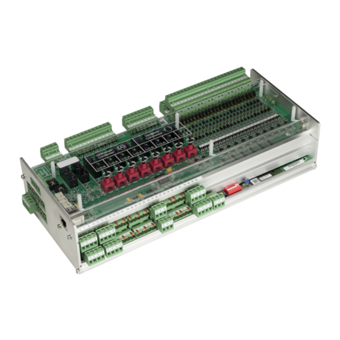
ECKELMANN
ECKELMANN VS 3015 CT User manual

ECKELMANN
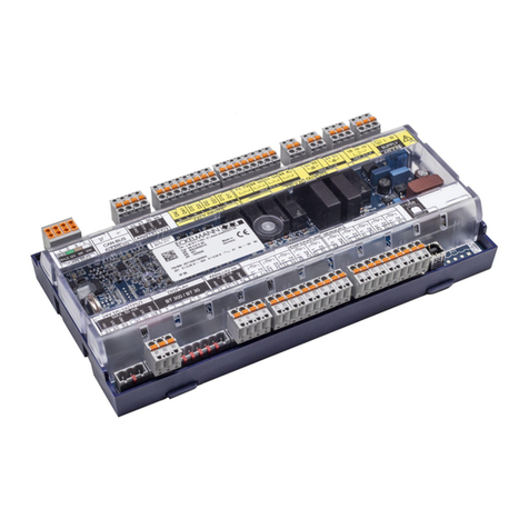
ECKELMANN WRG 3010 E User manual
ECKELMANN
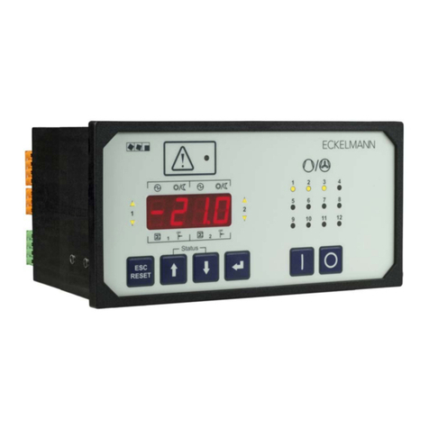
ECKELMANN Case Controller UA 4 E Series User manual
ECKELMANN
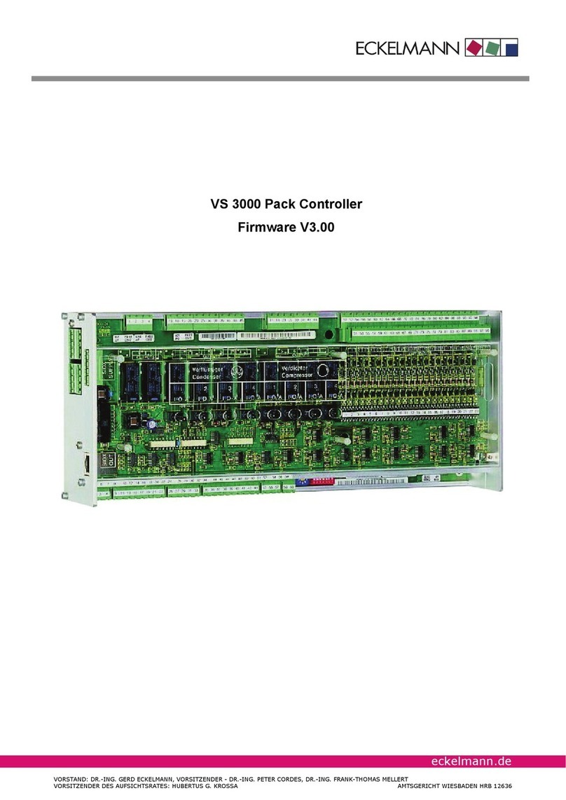
ECKELMANN VS 300 User manual
ECKELMANN
ECKELMANN VS 3000 User manual
ECKELMANN
ECKELMANN VS 3015 C User manual
ECKELMANN
ECKELMANN UA 400 User manual
ECKELMANN
ECKELMANN UA 300 D User manual
ECKELMANN
ECKELMANN UA 412 S User manual
