manuals.online logo
Brands
  1. Home
  2. •
  3. Brands
  4. •
  5. ECKELMANN
  6. •
  7. Controllers
  8. •
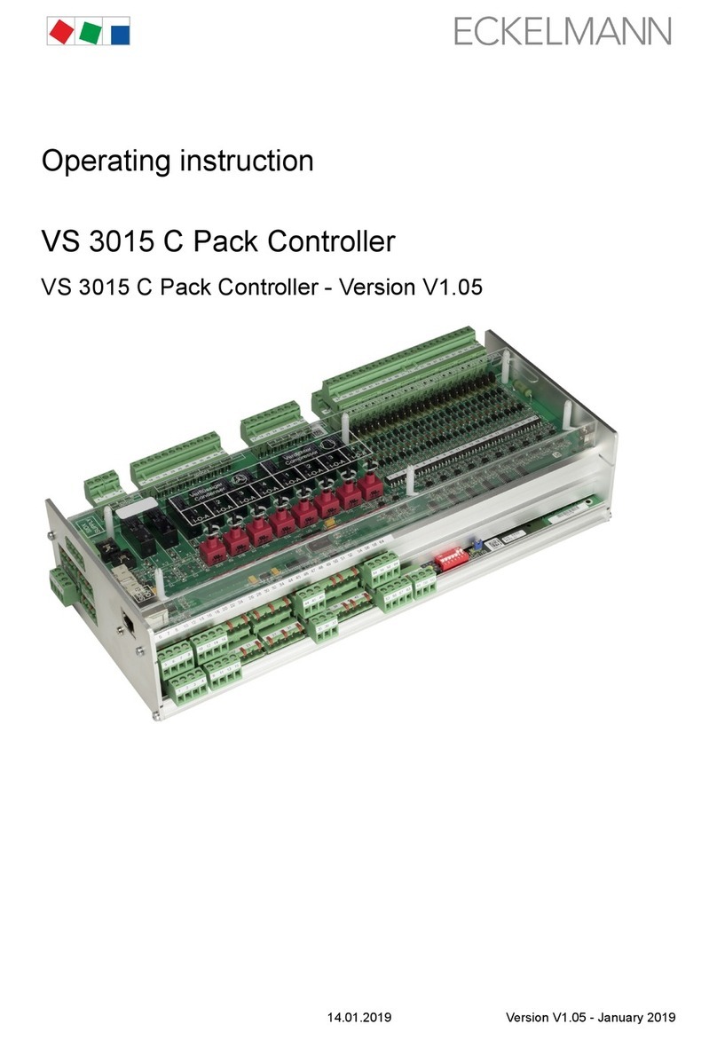
  9. ECKELMANN VS 3000 BS User manual

ECKELMANN VS 3000 BS User manual

eckelmann.de
VORSTAND: DR.-ING. GERD ECKELMANN, VORSITZENDER − DR.−ING. PETER CORDES, DR.-ING. FRANK-THOMAS MELLERT
VORSITZENDER DES AUFSICHTSRATES: HUBERTUS G. KROSSA AMTSGERICHT WIESBADEN HRB 12636
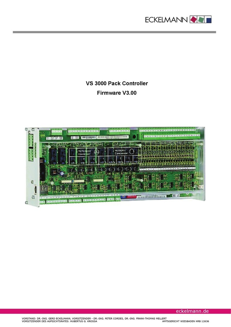
VS 3000 BS Pack Controller Firmware V2.22
Table of contents
i
E2007 − ECKELMANN | BERLINER STRASSE 161 | 65205 WIESBADEN | FON +49(0)611 7103-0 | FAX 49(0)611 7103-133 | eckelmann.de
Version 2.02 29. Nov. 2007
1 System Design of VS 3000 BS 1. . . . . . . . . . . . . . . . . . . . . . . . . . . . . . . . . . . . . . . .
2 Application of VS 3000 BS 3. . . . . . . . . . . . . . . . . . . . . . . . . . . . . . . . . . . . . . . . . . .
2.1 System extension options 4. . . . . . . . . . . . . . . . . . . . . . . . . . . . . . . . . . . . . . . . . . . . .
3 Function of VS 3000 BS 7. . . . . . . . . . . . . . . . . . . . . . . . . . . . . . . . . . . . . . . . . . . . . .
3.1 System configuration 7. . . . . . . . . . . . . . . . . . . . . . . . . . . . . . . . . . . . . . . . . . . . . . . . .
3.2 Low−pressure control / Compressor control 7. . . . . . . . . . . . . . . . . . . . . . . . . . . . . .
3.2.1 Setting parameters for LP sensor characteristic 8. . . . . . . . . . . . . . . . . . . . . . . . . . . . . . . .
3.2.2 Neutral zone 8. . . . . . . . . . . . . . . . . . . . . . . . . . . . . . . . . . . . . . . . . . . . . . . . . . . . . . . . . . . . . . .
3.2.3 Control algorithm 8. . . . . . . . . . . . . . . . . . . . . . . . . . . . . . . . . . . . . . . . . . . . . . . . . . . . . . . . . . .
3.3 Compressor control times 9. . . . . . . . . . . . . . . . . . . . . . . . . . . . . . . . . . . . . . . . . . . . .
3.4 Calculating setpoint 11. . . . . . . . . . . . . . . . . . . . . . . . . . . . . . . . . . . . . . . . . . . . . . . . . . .
3.4.1 Calculating setpoint by room temperature 11. . . . . . . . . . . . . . . . . . . . . . . . . . . . . . . . . . . . . .
3.5 Humidity shift 12. . . . . . . . . . . . . . . . . . . . . . . . . . . . . . . . . . . . . . . . . . . . . . . . . . . . . . . .
3.6 Second setpoint − Setpoint increase/decrease 13. . . . . . . . . . . . . . . . . . . . . . . . . . .
3.7 Booster/satellite operation 13. . . . . . . . . . . . . . . . . . . . . . . . . . . . . . . . . . . . . . . . . . . . .
3.8 Compressor control by refrigeration point 14. . . . . . . . . . . . . . . . . . . . . . . . . . . . . . . .
3.9 Compressor packs with suction gas bypass (evaporating pressure controller) 15
3.10 Compressor packs with plate−type heat exchanger 16. . . . . . . . . . . . . . . . . . . . . . .
3.11 Compressor packs with oil equalizer 17. . . . . . . . . . . . . . . . . . . . . . . . . . . . . . . . . . . .
3.12 Capacity−controlled compressors 17. . . . . . . . . . . . . . . . . . . . . . . . . . . . . . . . . . . . . . .
3.13 Load shedding 17. . . . . . . . . . . . . . . . . . . . . . . . . . . . . . . . . . . . . . . . . . . . . . . . . . . . . . .
3.14 Compressor base load rotation 18. . . . . . . . . . . . . . . . . . . . . . . . . . . . . . . . . . . . . . . . .
3.15 Compressor monitoring 18. . . . . . . . . . . . . . . . . . . . . . . . . . . . . . . . . . . . . . . . . . . . . . .
3.16 Safety loop 18. . . . . . . . . . . . . . . . . . . . . . . . . . . . . . . . . . . . . . . . . . . . . . . . . . . . . . . . . .
3.17 Monitoring low oil pressure cutout 19. . . . . . . . . . . . . . . . . . . . . . . . . . . . . . . . . . . . . .
3.18 Monitoring cylinder head temperature 19. . . . . . . . . . . . . . . . . . . . . . . . . . . . . . . . . . .
3.19 Monitoring high pressure 19. . . . . . . . . . . . . . . . . . . . . . . . . . . . . . . . . . . . . . . . . . . . . .
3.20 Monitoring low pressure 20. . . . . . . . . . . . . . . . . . . . . . . . . . . . . . . . . . . . . . . . . . . . . . .
3.21 Monitoring compressor starts 21. . . . . . . . . . . . . . . . . . . . . . . . . . . . . . . . . . . . . . . . . .
3.22 High−pressure control / Condenser control 21. . . . . . . . . . . . . . . . . . . . . . . . . . . . . . .
3.22.1 Setting parameter for HP sensor characteristic 22. . . . . . . . . . . . . . . . . . . . . . . . . . . . . . . . .
3.22.2 Neutral zone 22. . . . . . . . . . . . . . . . . . . . . . . . . . . . . . . . . . . . . . . . . . . . . . . . . . . . . . . . . . . . . . .
3.22.3 Control algorithm 22. . . . . . . . . . . . . . . . . . . . . . . . . . . . . . . . . . . . . . . . . . . . . . . . . . . . . . . . . . .
Table of contents
ii Version 2.02 29. Nov. 2007
3.22.4 Control algorithm with step controller 23. . . . . . . . . . . . . . . . . . . . . . . . . . . . . . . . . . . . . . . . . .
3.22.5 Calculating setpoint with step controller 23. . . . . . . . . . . . . . . . . . . . . . . . . . . . . . . . . . . . . . . .
3.22.6 Condenser fan control times with step controller 24. . . . . . . . . . . . . . . . . . . . . . . . . . . . . . . .
3.22.7 Control algorithm with continuous control 26. . . . . . . . . . . . . . . . . . . . . . . . . . . . . . . . . . . . . .
3.22.8 Calculating setpoint with continuous control 27. . . . . . . . . . . . . . . . . . . . . . . . . . . . . . . . . . . .
3.22.9 Heat recovery mode 27. . . . . . . . . . . . . . . . . . . . . . . . . . . . . . . . . . . . . . . . . . . . . . . . . . . . . . . .
3.23 HP setpoint increase 28. . . . . . . . . . . . . . . . . . . . . . . . . . . . . . . . . . . . . . . . . . . . . . . . . .
3.24 Fan protection / HP base load rotation 29. . . . . . . . . . . . . . . . . . . . . . . . . . . . . . . . . .
3.25 Monitoring condenser fan motors 29. . . . . . . . . . . . . . . . . . . . . . . . . . . . . . . . . . . . . . .
3.26 Starting characteristics 30. . . . . . . . . . . . . . . . . . . . . . . . . . . . . . . . . . . . . . . . . . . . . . . .
3.26.1 First start 30. . . . . . . . . . . . . . . . . . . . . . . . . . . . . . . . . . . . . . . . . . . . . . . . . . . . . . . . . . . . . . . . . .
3.26.2 Restart 30. . . . . . . . . . . . . . . . . . . . . . . . . . . . . . . . . . . . . . . . . . . . . . . . . . . . . . . . . . . . . . . . . . . .
3.27 Monitoring refrigerant level 30. . . . . . . . . . . . . . . . . . . . . . . . . . . . . . . . . . . . . . . . . . . .
3.28 Monitoring burst disk 30. . . . . . . . . . . . . . . . . . . . . . . . . . . . . . . . . . . . . . . . . . . . . . . . . .
3.29 Monitoring external alarm / speed adjuster 31. . . . . . . . . . . . . . . . . . . . . . . . . . . . . . .
3.30 Disabling refrigeration points 31. . . . . . . . . . . . . . . . . . . . . . . . . . . . . . . . . . . . . . . . . . .
3.31 Discharge gas defrosting 31. . . . . . . . . . . . . . . . . . . . . . . . . . . . . . . . . . . . . . . . . . . . . .
3.31.1 Setpoints for discharge gas defrosting 32. . . . . . . . . . . . . . . . . . . . . . . . . . . . . . . . . . . . . . . . .
3.31.2 Actual values for discharge gas defrosting 33. . . . . . . . . . . . . . . . . . . . . . . . . . . . . . . . . . . . .
3.31.3 Manual control of D2D 33. . . . . . . . . . . . . . . . . . . . . . . . . . . . . . . . . . . . . . . . . . . . . . . . . . . . . .
3.31.4 Sequence of joint Z2 discharge gas defrosting 34. . . . . . . . . . . . . . . . . . . . . . . . . . . . . . . . . .
3.31.5 Sequence of Z2 display case discharge gas defrosting 35. . . . . . . . . . . . . . . . . . . . . . . . . .
3.31.6 Sequence of Z2 coldroom discharge gas defrosting 35. . . . . . . . . . . . . . . . . . . . . . . . . . . . .
3.31.7 Sequence of Z1 discharge gas defrosting 36. . . . . . . . . . . . . . . . . . . . . . . . . . . . . . . . . . . . . .
3.31.8 Sequence of Z2 discharge gas defrosting with defrost mode set to
El. With UA 300 37. . . . . . . . . . . . . . . . . . . . . . . . . . . . . . . . . . . . . . . . . . . . . . . . . . . . . . . . . . . . . . . . . . . . . . . . . .
3.31.9 Discharge gas defrosting in fault conditions 38. . . . . . . . . . . . . . . . . . . . . . . . . . . . . . . . . . . .
4 Installation and Startup of VS 3000 BS 39. . . . . . . . . . . . . . . . . . . . . . . . . . . . . . . .
4.1 Connection and safety notes 39. . . . . . . . . . . . . . . . . . . . . . . . . . . . . . . . . . . . . . . . . . .
4.2 DIN rail mounting 40. . . . . . . . . . . . . . . . . . . . . . . . . . . . . . . . . . . . . . . . . . . . . . . . . . . . .
4.3 Basic parameter settings on hardware 40. . . . . . . . . . . . . . . . . . . . . . . . . . . . . . . . . .
4.3.1 Basic settings with S1 41. . . . . . . . . . . . . . . . . . . . . . . . . . . . . . . . . . . . . . . . . . . . . . . . . . . . . . .
4.3.2 Basic settings with S2 43. . . . . . . . . . . . . . . . . . . . . . . . . . . . . . . . . . . . . . . . . . . . . . . . . . . . . . .
4.4 Basic parameter settings in software 43. . . . . . . . . . . . . . . . . . . . . . . . . . . . . . . . . . . .
4.5 Commissioning of speed controlled condenser fans / compressors 45. . . . . . . . .
4.5.1 Procedure for commissioning an installation 45. . . . . . . . . . . . . . . . . . . . . . . . . . . . . . . . . . . .
4.6 Replacing the battery 49. . . . . . . . . . . . . . . . . . . . . . . . . . . . . . . . . . . . . . . . . . . . . . . . .
Table of contents
iii
E2007 − ECKELMANN | BERLINER STRASSE 161 | 65205 WIESBADEN | FON +49(0)611 7103-0 | FAX 49(0)611 7103-133 | eckelmann.de
Version 2.02 29. Nov. 2007
4.7 Installing firmware update 52. . . . . . . . . . . . . . . . . . . . . . . . . . . . . . . . . . . . . . . . . . . . .
4.7.1 Requirements 52. . . . . . . . . . . . . . . . . . . . . . . . . . . . . . . . . . . . . . . . . . . . . . . . . . . . . . . . . . . . . .
4.7.2 Updating current firmware 53. . . . . . . . . . . . . . . . . . . . . . . . . . . . . . . . . . . . . . . . . . . . . . . . . . .
5 Pin and Terminal Assignments of VS 3000 BS 57. . . . . . . . . . . . . . . . . . . . . . . . .
5.1 Pin assignments 58. . . . . . . . . . . . . . . . . . . . . . . . . . . . . . . . . . . . . . . . . . . . . . . . . . . . .
5.2 Inputs/outputs for 4 compressor capacity/4 fan stages 61. . . . . . . . . . . . . . . . . . . .
5.3 Inputs/outputs for 8 compressor capacity/8 fan stages 64. . . . . . . . . . . . . . . . . . . .
5.4 Inputs/outputs of SIOX D2D expansion module for discharge gas defrosting 67.
6 Operating Modes of VS 3000 BS 69. . . . . . . . . . . . . . . . . . . . . . . . . . . . . . . . . . . . . .
6.1 Emergency manual−automatic mode selection 69. . . . . . . . . . . . . . . . . . . . . . . . . . .
6.2 Service−Mode 69. . . . . . . . . . . . . . . . . . . . . . . . . . . . . . . . . . . . . . . . . . . . . . . . . . . . . . . .
6.3 Displaying operating status 70. . . . . . . . . . . . . . . . . . . . . . . . . . . . . . . . . . . . . . . . . . . .
7 Operation of VS 3000 BS 71. . . . . . . . . . . . . . . . . . . . . . . . . . . . . . . . . . . . . . . . . . . . .
7.1 Operation with CI 3000 Store Computer or AL 300 Operator Terminal 71. . . . . . .
7.2 Menus and screens 72. . . . . . . . . . . . . . . . . . . . . . . . . . . . . . . . . . . . . . . . . . . . . . . . . . .
7.3 Operation / Parameter setting of VS 3000 BS Pack Controller 75. . . . . . . . . . . . . .
8 Menu Structure of VS 3000 BS 77. . . . . . . . . . . . . . . . . . . . . . . . . . . . . . . . . . . . . . .
8.1 Menu tree 78. . . . . . . . . . . . . . . . . . . . . . . . . . . . . . . . . . . . . . . . . . . . . . . . . . . . . . . . . . .
8.1.1 Menu 0 Main Menu 81. . . . . . . . . . . . . . . . . . . . . . . . . . . . . . . . . . . . . . . . . . . . . . . . . . . . . . . . .

8.1.2 Menu 1 Summary 81. . . . . . . . . . . . . . . . . . . . . . . . . . . . . . . . . . . . . . . . . . . . . . . . . . . . . . . . . .
8.1.3 Menu 2 Actual values 82. . . . . . . . . . . . . . . . . . . . . . . . . . . . . . . . . . . . . . . . . . . . . . . . . . . . . . .
8.1.4 Menu 3 Setpoints 86. . . . . . . . . . . . . . . . . . . . . . . . . . . . . . . . . . . . . . . . . . . . . . . . . . . . . . . . . . .
8.1.5 Menu 4 Clock 105. . . . . . . . . . . . . . . . . . . . . . . . . . . . . . . . . . . . . . . . . . . . . . . . . . . . . . . . . . . . . .
8.1.6 Menu 5 Messages 106. . . . . . . . . . . . . . . . . . . . . . . . . . . . . . . . . . . . . . . . . . . . . . . . . . . . . . . . . .
8.1.7 Menu 6 Operating data 106. . . . . . . . . . . . . . . . . . . . . . . . . . . . . . . . . . . . . . . . . . . . . . . . . . . . . .
8.1.8 Menu 7 Default settings 115. . . . . . . . . . . . . . . . . . . . . . . . . . . . . . . . . . . . . . . . . . . . . . . . . . . . .
8.1.9 Menu 8 Service Mode 116. . . . . . . . . . . . . . . . . . . . . . . . . . . . . . . . . . . . . . . . . . . . . . . . . . . . . . .
9 Alarms and Messages of VS 3000 BS 119. . . . . . . . . . . . . . . . . . . . . . . . . . . . . . . . .
9.1 Reporting system 119. . . . . . . . . . . . . . . . . . . . . . . . . . . . . . . . . . . . . . . . . . . . . . . . . . . . .
9.2 Structure of alarms/messages 119. . . . . . . . . . . . . . . . . . . . . . . . . . . . . . . . . . . . . . . . . .
9.3 Types of alarm 120. . . . . . . . . . . . . . . . . . . . . . . . . . . . . . . . . . . . . . . . . . . . . . . . . . . . . . .
9.3.1 Process fault alarms 120. . . . . . . . . . . . . . . . . . . . . . . . . . . . . . . . . . . . . . . . . . . . . . . . . . . . . . . .
9.3.2 System fault alarms 122. . . . . . . . . . . . . . . . . . . . . . . . . . . . . . . . . . . . . . . . . . . . . . . . . . . . . . . .
9.4 Archiving of operating data 123. . . . . . . . . . . . . . . . . . . . . . . . . . . . . . . . . . . . . . . . . . . .
Table of contents
iv Version 2.02 29. Nov. 2007
9.4.1 Compressor/fan operating hours 123. . . . . . . . . . . . . . . . . . . . . . . . . . . . . . . . . . . . . . . . . . . . .
9.4.2 Daily run times 123. . . . . . . . . . . . . . . . . . . . . . . . . . . . . . . . . . . . . . . . . . . . . . . . . . . . . . . . . . . . .
10 Specifications of VS 3000 BS 125. . . . . . . . . . . . . . . . . . . . . . . . . . . . . . . . . . . . . . . .
10.1 Electrical Data 125. . . . . . . . . . . . . . . . . . . . . . . . . . . . . . . . . . . . . . . . . . . . . . . . . . . . . . .
10.2 Mechanical data of VS 3000 BS 126. . . . . . . . . . . . . . . . . . . . . . . . . . . . . . . . . . . . . . . .
10.3 Mechanical data of SIOX extension module 126. . . . . . . . . . . . . . . . . . . . . . . . . . . . .
System Design of VS 3000 BS
1
E2007 − ECKELMANN | BERLINER STRASSE 161 | 65205 WIESBADEN | FON +49(0)611 7103-0 | FAX 49(0)611 7103-133 | eckelmann.de
Version 2.02 29. Nov. 2007
1 System Design of VS 3000 BS
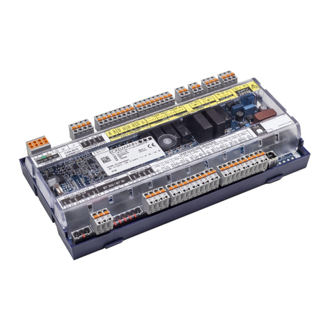
The basic module of the VS 3000 BS (Booster/Satellite) Pack Controller consists of:
− One analog module
− One SIOX expansion module (digital I/O module)
The controller is of modular design and can be upgraded to a maximum of two SIOX extension modules (see
illustration below). The following expansion stages are available:
Base module
VS 3000 BS
TTY
RS 232/485
CAN bus
CI 350
GLT
LDS new
CI 3000
AL 300
Base module
4 compressors and
4 fans
Base module with one extension module
8 compressors and 8 fans
ZNR. 51203 55 130 E2
Optionally for
hotgas defrost
Optionally for
hotgas defrost
SIOXSIOX
OUT
IN
OUT
IN
SIOX Supply
Digital output
4 x two-way
contact
4 x normal open
contact
Digital output
4 x two-way
contact
4 x normal open
contact
1 x anlog output
0..10V (4..20 mA)
(speed actuator FC)
Digital output
4 x two-way
contact
6 x normal open
contact
Extension module
SIOX
Extension module
SIOX
23 x digital inputs 230 V
1 x input humidity sensor
4...20 mA (0..10V)
3 x analog inputs
4...20 mA (0..10V)
(e.g. pressure transmitter)
8 x analog input
temperature sonde
PT 1000 (e.g. cyl. head temperature)
2 x inputs temperature sensors
PT 1000
(e.g. room- and outdoor temperature)
12 x digital inputs 230 V
MODEESC
PRIO 1
PRIO 2
,
9
WXYZ
7
PQRS
8
TUV
6
MNO
4
GHI
5
JKL
3
DEF
2
ABC
1
0
ALARM
RESET
See Section 5 − Pin and Terminal Assignments for electrical connections of the VS 3000 BS Pack Controller.
Basic version:
Digital inputs/outputs
23 inputs 230 V
10 outputs 230 V − Relay outputs
System Design of VS 3000 BS
2Version 2.02 29. Nov. 2007
Analog inputs/outputs
8 inputs PT1000 − Connection for PT1000 temperature sensors (cylinder head temperature sensors)
2 inputs PT1000 − Connection for PT1000 temperature sensors (room and outdoor temperature sensors)
3 inputs / 4−20 mA (0−10 V) − Connection for pressure transducers
1 input / 4−20 mA (0−10 V) − Connection for humidity sensor
1 output / 0−10 V (0−20 mA) − Connection for speed adjuster for continuous fan control
SIOX Supply − Power supply for SIOX extension module
Ports:
CAN bus: Communication within new LDS System
TTY: Communication within earlier LDS System
RS232: Communication between LDS System and building control system,
connection for firmware update
RS485: Connection for building control system (BCS)
SIOX OUT: Connection for data transfer to SIOX extension modules
Application of VS 3000 BS
3
E2007 − ECKELMANN | BERLINER STRASSE 161 | 65205 WIESBADEN | FON +49(0)611 7103-0 | FAX 49(0)611 7103-133 | eckelmann.de
Version 2.02 29. Nov. 2007
2 Application of VS 3000 BS
Functions provided in the VS 3000 BS Pack Controller for refrigeration compressor packs and condensers
are as follows:
SControl
SRegulation
SFault reporting
SFault archiving
SMonitoring
SArchiving
These functions are as follows:
Compressor control for two temperature ranges equipped with maximum
4 compressors each with 2 capacity stages or
2 compressors each with 3 capacity stages or
8 stand−alone compressors without capacity control in booster or satellite operation
Low−pressure control/compressor control:
− Step controller
Base load rotation
Compressor monitoring
Load shedding
High−pressure control/fan control
− Step controller
− Speed controller
Base load rotation/Fan overload protection
Data archiving
− Messages
− Starts
− Run times
− Activity/Utilization
Liquid level monitoring
Application of VS 3000 BS
4Version 2.02 29. Nov. 2007
Monitoring
− Motor overload cutout (fans)
− Motor overload cutout (compressors)
− Bursting disk
− Low oil pressure cutout
− Cylinder head temperature
− High pressure
− Low pressure
− Refrigerant level
− External alarm
Discharge gas defrosting
− Two−pipe discharge gas defrosting D2D
2.1 System extension options
The following diagrams show typical applications of the VS 3000 BS Pack Controller. Depending on the exten-
sion stage, control can be provided for either 4 or maximum 8 relay/control stages for compressor stages or
condenser stages (see Section 1 − System Design):
Satellite operation − with common condenser
ZNR. 51203 55 431 E1
LP-Z2
LT
LP-Z1
NT
to NT
refrigeration point
0LT
p
0NT
p
from LT
refrigeration point
from NT
refrigeration point
to LT
refrigeration point
VS 3000 BS
LP-Z2LP-Z1 HP
C
p
HP
Application of VS 3000 BS
5
E2007 − ECKELMANN | BERLINER STRASSE 161 | 65205 WIESBADEN | FON +49(0)611 7103-0 | FAX 49(0)611 7103-133 | eckelmann.de
Version 2.02 29. Nov. 2007
Controller for booster operation − with common condenser
ZNR. 51203 55 530 E1
LP-Z1
NT
LP-Z2
LT
0NT
p
0LT
p
from NT
refrigeration point
to NT
refrigeration point
from LT
refrigeration point
to LT
refrigeration point
C
p
HP
VS 3000 BS
LP-Z2LP-Z1 HP
Application of VS 3000 BS
6Version 2.02 29. Nov. 2007
Notice:
Function of VS 3000 BS
7
E2007 − ECKELMANN | BERLINER STRASSE 161 | 65205 WIESBADEN | FON +49(0)611 7103-0 | FAX 49(0)611 7103-133 | eckelmann.de
Version 2.02 29. Nov. 2007
3 Function of VS 3000 BS
3.1 System configuration
The VS 3000 BS Pack Controller contains two low−pressure control loops (LP, compressor control) and one high−
pressure control loop (HP, condenser control). Two different temperature ranges are provided for compressor con-
trol; see also Section 2 − Application).
As standard, the Z1 temperature range is operated in the normal−temperature (NT) range and Z2 in the low−tem-
perature (LT) range. However, Z2 can also be operated in the NT range, enabling the controller to control two NT
loops.
Compressor control largely covers the following control and regulating functions:
Low−pressure control (LP, compressor control) for single−circuit systems
SLow−pressure control (LP, compressor control) for single−circuit systems, normal−temperature (NT) and low−
temperature (LT) ranges
SLoad shedding
SBase load rotation
SCompressor monitoring
SSafety loop
STwo−pipe discharge gas defrosting D2D
High−pressure control (HP, condenser control) for single−circuit systems
3.2 Low−pressure control / Compressor control
The purpose of low−pressure control is to maintain pressure on the low (suction) side of the system at a defined
setpoint. The VS 3000 BS provides the following control method for this purpose:
SStep controller
− Control by loading and unloading compressor stages or compressor capacity stages
The setpoint for the Z1 and Z2 temperature ranges is defined as a function of room (ambient) temperature.
Actual values are detected by two pressure transducers, one for each temperature range, with continuous cur-
rent output (4 to 20 mA) or voltage output (0 to 10 V).
8Version 2.02 29. Nov. 2007
3.2.1 Setting parameters for LP sensor characteristic
The VS 3000 BS Pack Controller works with linear−characteristic continuous pressure transducers. The pressure
inputs can be matched to various transducers with linear characteristic. Transducers with either current output (4 to
20 mA) or voltage output (0 to 10 V) may be used.
Jumpers must be changed accordingly on the controller for voltage−output transducers!
The default configuration is for current inputs!
The following parameters (Menu 3−1−a) are used to match the controller to the pressure transducer:
1.Z1 sensor
− The Z1 sensor must be selected for either continuous current output 4 to 20 mA or
continuous voltage output 0 to 10 V.
2.Z2 sensor
− The Z2 sensor must be selected for either continuous current output 4 to 20 mA or
continuous voltage output 0 to 10 V.
3.On the VS 3000 BS, the sensor characteristic parameters for the Z1and Z2 temperature ranges are
entered separately.
p0−Z1 4 mA / p0−Z1 0 V Pressure at 4 mA or 0 V at output of Z1 pressure sensor Z1
p0−Z1 20 mA / p0−Z1 10 V Pressure at 20 mA or 10 V at output of Z1 pressure sensor Z1
p0−Z2 4 mA / p0−Z2 0 V Pressure at 4 mA or 0 V at output of Z1 pressure sensor Z2
p0−Z2 20 mA / p0−Z2 10 V Pressure at 20 mA or 10 V at output of Z1 pressure sensor Z2
Changing any of these parameters causes a Sensor Type Change message to be generated.
Incorrect parameter setting can result in severely impaired function.
3.2.2 Neutral zone
No compressor actuation takes place as long as the control error remains within a definable neutral zone.
3.2.3 Control algorithm
Low pressure as detected by an A/D converter is compared with the setpoint:
Controlerror +Actualvalue(t0_Act)*Setpoint(t0_Setp)
Pressure change within the controller cycle time is also evaluated. When the control error is positive and pres-
sure is rising, the step switch moves one step up. As a result the compressor having the shortest run time is en-
abled.
When the control error is negative and pressure is falling, the step switch moves one step down. As a result the
compressor having the longest run time is disabled.
No compressor actuation takes place when the control error is within a definable neutral zone.
On the VS 3000 BS, both temperature ranges have neutral zones. The control algorithm is identical for both
temperature ranges. Controller cycle time is 1 second.
9
E2007 − ECKELMANN | BERLINER STRASSE 161 | 65205 WIESBADEN | FON +49(0)611 7103-0 | FAX 49(0)611 7103-133 | eckelmann.de
Version 2.02 29. Nov. 2007
In the wet vapor range the temperature is clearly governed by the refrigerant and pressure:
t = f (p, refrigerant). The VS 3000 BS calculates temperatures from the pressures measured as a
function of the refrigerant used. Exclusively temperature measurements are used for control.
In this manual therefore, temperatures (t0, tc) stand for pressures (p0, pc).
VS 3000 BS control algorithm LP step controller
ZNR. 51203 60 130 E0
Neutrale Zone NZ (Z1)
t
Time
0
Suction pressure
t0 Serp
t0 Serp
t0 Serp
t0 Serp
Step up No step Step down No step
t0 Serp
Time
Neutrale Zone NZ (Z2)
t0
Suction pressure
t0 Serp
t0 Serp
t0 Serp
t0 Serp
Step up No step Step down No step
t0 Serp
- 1,0 NZ (Z1)
- 0,5 NZ (Z1)
+ 0,5 NZ (Z1)
+ 1,0 NZ (Z1)
- 1,0 NZ (Z2)
- 0,5 NZ (Z2)
+ 0,5 NZ (Z2)
+ 1,0 NZ (Z2)
3.3 Compressor control times
Compressor actuation takes place only outside the neutral zone, after a certain time for loading or unloading has
passed and when the control error has exceeded a defined level (neutral zone).
The time delay is dependent on the actual control error. With a large control error, actuation takes place in a
shorter time than when the control error is smaller. The control time is calculated as the sum of basic time tb and
variable time tv. Differentiation is made between up and down stepping of the step controller.
The variable time is inversely proportional to the control error. At maximum control error the variable time is tv =
0. As the control error decreases, time tv automatically increases up to a defined maximum. Basic time and
maximum variable time for loading (starting) and unloading (stopping) can be programmed as parameters for
each capacity stage.
Relationships for determining control times are as follows:
t+tb)tv
tb= Basic time: Can be programmed for each loading of a compressor capacity stage.
tv= Variable control time
For tv:
tv+tv_max *ǒtv_max @dtǓ
dt_max
10 Version 2.02 29. Nov. 2007
The following applies:
dt§dt_max is equal to dt+dt_max
tv= Variable control time
tv_max = Maximum variable control time (definable for each capacity stage)
dt= Control error
dt_max = Maximum control error/constant (definable)
The start delay commences after loading a compressor capacity stage or when low pressure reaches a value
greater than the upper limit of the neutral zone. The stop delay commences after unloading a compressor
capacity stage or when the low pressure reaches a value less than the lower limit of the neutral zone.
Control time is calculated on every run of the controller. This entails recalculating the variable time and
comparing the time elapsed since the last control time to the calculated time. If the calculated control time is less
than or equal to the elapsed time, compressor actuation takes place when the controlled variable p0is outside
the neutral zone.
Calculation of control times is identical for both temperature ranges. Variable control time is tv= 0 when the
booster/satellite compressors are directly controlled by the refrigeration points, the control time then consisting
of only the basic time t = tb.
Calculation of control time is shown in the following diagram:
t = tb.
ZNR. 51203 60 230 E1
Control error dt [°C]
Run time [s]
VS 3000 BS Compressor fan run times
0
2
4
6
dt
8
10 dt max
12
0
20
40
60
80
100
120
140
120
160
180
200
220
240
t
v max
Basic time t
b
Runtimet=t +t
vb
t+t
v maxb
t
b
t
v
11
E2007 − ECKELMANN | BERLINER STRASSE 161 | 65205 WIESBADEN | FON +49(0)611 7103-0 | FAX 49(0)611 7103-133 | eckelmann.de
Version 2.02 29. Nov. 2007
3.4 Calculating setpoint
3.4.1 Calculating setpoint by room temperature
The t0setpoint is calculated as a function of room temperature (setpoint shift). Room (ambient) temperature is
supplied either by a PT1000 sensor connected direct to a pack controller input or via the CAN bus by another
controller in the system.
t0+t0_min )ƪǒt0_max *t0_minǓ@ǒtr*tr_maxǓƫ
ƪǒtr_min *tr_maxǓƫ
t0= t0setpoint
t0_max = Maximum t0setpoint
t0_min = Minimum t0setpoint
tr= Current room temperature
tr_max = Maximum room temperature for setpoint shift
tr_min = Minimum room temperature for setpoint shift
With a room temperature of tr> tr_max or tr< tr_min the setpoint t0is defined as a constant as follows:
For t < tr_min t0= t0_max
For t > tr_max t0=t0_min
ZNR. 51203 60 330 E0
t0min
t0 max
Room temperature t [°C]
Low-pressure control
r
-35
-30
-25
-20
-15
-10
-5
-0
0 5 10 15 20 25 30 35
tr max
trmin
t0
Suction pressure
Temperatures t0_max, t0_min, tr_min and tr_max can be set as parameters. Additionally, allowance can be made for
the air humidity via an analog input. The pressure setpoint for actual control is determined from a conversion
table stored in the program. Provision is currently made for the following refrigerants when converting t0to the
corresponding pressure:
R22, R502, R134a, R402A, R404A, R717, R1270, R507, R407c, R410a, R290,
R744 (no transcritical operation)
Calculation of setpoint is identical for both temperature ranges. Temperatures t0_max, t0_min, tr_min and tr_max can
be set as parameters for both temperature ranges.
12 Version 2.02 29. Nov. 2007
3.5 Humidity shift
The humid. adapt. parameter can be used to define whether the t0setpoint is also to be matched as a function of
air humidity. Shift of the to setpoint by the air humidity can be activated separately for the Z1 and Z2 temperature
ranges and for operation at the first and second setpoint
(Menu 3−2−1 Z1−Day, Menu 3−2−2 Z1−Night, Menu 3−2−3 Z2−Day, Menu 3−2−4 Z1−Night).
The air humidity signal can be supplied either by the humidity sensor or via the CAN bus by another pack
controller. A temperature offset t0offset is then formed as a function of the air humidity and added to t0_Setp:
ZNR. 51203 60 430 E0
t
0 off set
Relative humidity [%]
Humidity shift
-2
-1
-0
1
0 10203040506070
t0
2
80 90 100
[K]
Ambient data
The following quantities used for setpoint shift can be supplied either via sensors connected to the pack
controller or via the CAN bus from another pack controller.
- Room temperature (t0shift)
- Outdoor temperature (tc shift)
- Humidity (t0shift)
Response of the controller is determined by the parameters Room temp., Outd.temp., Humidity and NodeNr
Env.dat. Data (Menu 3 −1).
The parameters Room temp., Outd.temp. and Humidity can be used to define whether sensors are connected
direct to the controller. If one of these parameters is set to N, the additional parameter NodeNr Env.dat. will be
shown in the operating screen and can be used as required to enter the Node No. of the pack controller that
supplies the required ambient data.
If no ambient data is to be received via the CAN bus, the parameter NodeNr Env.dat. Data can be set t0−−. This
deactivates setpoint shift.
13
E2007 − ECKELMANN | BERLINER STRASSE 161 | 65205 WIESBADEN | FON +49(0)611 7103-0 | FAX 49(0)611 7103-133 | eckelmann.de
Version 2.02 29. Nov. 2007
3.6 Second setpoint − Setpoint increase/decrease
With low−pressure control there is the option of programming a second characteristic that can be activated by
the internal week timer or a digital input of the controller. Polarity of the digital input signal is definable. Setpoint
increase/decrease allows better matching to night and weekend operation.
Setpoint toggle changes the following controller parameters:
- Temperature setpoints Z1/Z2
- Neutral zone Z1/Z2
- Control constant Z1/Z2
- Control times Z1/Z2
- Humidity shift Z1/Z2
Setpoint toggle takes place jointly for the two temperature ranges Z1 and Z2.
3.7 Booster/satellite operation
In the layout of refrigeration systems differentiation is made between three modes: normal, satellite and booster
mode. In normal mode, refrigeration circuits at different evaporating temperature levels are operated in fully
independent systems. Each circuit contains a compressor unit, a condensing unit and connected refrigeration
points (display cases, coldrooms).
By contrast, in satellite and booster mode the different refrigeration circuits are operated with only one condensing
unit and according only one common high−pressure line. The VS 3000 BS Pack Controller is specifically designed
for booster or satellite mode.
In satellite mode, operation with a single condensing unit is achieved by simply combining the high−pressure lines
of the compressors provided for each temperature level and conducting them through one condenser. Refrigerant
is fed to the refrigeration points from a common receiver.
In booster mode the refrigeration points are similarly supplied by the same liquid line. Whereas the suction lines of
the Z1/NT circuit connect direct to the main compressors, refrigerant from the Z2/LT refrigeration points first passes
through the booster stage. Pressure of the refrigerant from the Z2/LT refrigeration points is lower owing to the lower
evaporating temperature. In the booster stage it is increased to the pressure level in the suction lines from the
Z1/NT refrigeration points. The illustrations below show the schematic layout for satellite and booster mode.
Condensor
receiver
from Z1
refrigeration
points
pZ1
0
from Z2
refrigeration
points
Condensor
Z1-
Compressor
pZ2
0
Z2-
Compressor
1..x 1..x
to Z1/Z2
refrigeration
points
ZNR. 51203 60 530 E0
Satelite
14 Version 2.02 29. Nov. 2007
Condensor
receiver
from Z1
refrigeration
points
pZ1
0
from Z2
refrigeration
points
Condensor
Z1-
Compressor
pZ2
0
Z2-
Compressor
1..x 1..x
to Z1/Z2
refrigeration
points
ZNR. 51203 60 630 E0
Booster
SSatellite mode
In satellite mode the compressors of both temperature ranges are controlled independently by the low pressure.
SBooster mode
When all Z1 compressors are at standstill and Z2 compressors are loaded, the first Z1 compressor is loaded
immediately on exceeding the setpoint plus half of the neutral zone. In other words, control times are ignored!
The control times remain ignored for the first compressor.
Each additional Z1 compressor is loaded after the basic and variable load time elapses. When low pressure
decreases in the Z1 range, the Z1 compressors are unloaded after the basic and variable unload time elapses.
However one compressor remains in operation regardless of suction pressure. The last remaining Z1
compressor is not stopped until all Z2 compressors have been unloaded.
3.8 Compressor control by refrigeration point
Control of the booster/satellite compressors (Z2 temperature range) either by low pressure or direct by
refrigeration point (case/coldroom) must be programmed on the pack controller. In Menu 3−1 choosing the
parameter Booster/Sat.cont →opens the following list:
-Refrig pt
-Pressure /
Compressor control by refrigeration point requires refrigeration point control to be activated in this list.
On exiting the list, the parameter Refr.Pt.Nd.No. xx (Refrigeration Point Node No.) appears behind the
parameter Booster/Sat.cont →.
The refrigeration point CAN bus node address entered tells the controller which case/coldroom controller can
load or unload the booster/satellite compressor (CAN bus address 1 to 99). If only one compressor is installed,
the compressor output follows the solenoid valve of the refrigeration point. When several compressors are
installed, the first compressor is loaded without delay.
Additional compressors are loaded after the programmable basic time tb elapses. The compressor loaded is
always that having the shortest running time. If compressor capacity stages are to be unloaded, a single
compressor will be stopped immediately. When several compressors are installed, the first compressor is
unloaded without delay.
Additional compressors are unloaded after the programmable basic time tb elapses. The compressor unloaded
is always that having the longest running time. Low pressure is monitored with the help of the Z2 pressure
transducer. If pressure drops below a definable low limit, the compressor is disabled until pressure again rises
above the limit.
This limit (t0Comp OFF Z2) can be defined in Menu 3−4. Monitoring of starts per hour is not active when
compressors are controlled by refrigeration point. In compressor control by refrigeration point the compressor is

Other ECKELMANN Controllers manuals

ECKELMANN UA 412 S User manual

ECKELMANN

ECKELMANN UA 412 S User manual

ECKELMANN UA 400 User manual

ECKELMANN

ECKELMANN UA 400 User manual

ECKELMANN VS 3010 BS User manual

ECKELMANN

ECKELMANN VS 3010 BS User manual

ECKELMANN Case Controller UA 4 E Series User manual

ECKELMANN

ECKELMANN Case Controller UA 4 E Series User manual

ECKELMANN VS 300 User manual

ECKELMANN

ECKELMANN VS 300 User manual

ECKELMANN UA 300 D User manual

ECKELMANN

ECKELMANN UA 300 D User manual

ECKELMANN VS 3015 C User manual

ECKELMANN

ECKELMANN VS 3015 C User manual

ECKELMANN UA 410 L User manual

ECKELMANN

ECKELMANN UA 410 L User manual

ECKELMANN WRG 3010 E User manual

ECKELMANN

ECKELMANN WRG 3010 E User manual

ECKELMANN UA 410 D User manual

ECKELMANN

ECKELMANN UA 410 D User manual

ECKELMANN VS 3015 CT User manual

ECKELMANN

ECKELMANN VS 3015 CT User manual

ECKELMANN VS 3000 User manual

ECKELMANN

ECKELMANN VS 3000 User manual

ECKELMANN UA 410 L Case Controller User manual

ECKELMANN

ECKELMANN UA 410 L Case Controller User manual

Popular Controllers manuals by other brands

GRASS VALLEY K2 Dyno S user manual

GRASS VALLEY

GRASS VALLEY K2 Dyno S user manual

EMKO ESM-3712-CN instruction manual

EMKO

EMKO ESM-3712-CN instruction manual

BENSHAW RediStart EXEXMVRMX3 Series user manual

BENSHAW

BENSHAW RediStart EXEXMVRMX3 Series user manual

Dräger REGARD-1 Installation, operation and maintenance

Dräger

Dräger REGARD-1 Installation, operation and maintenance

Siemens Simatic S7-300 Getting started

Siemens

Siemens Simatic S7-300 Getting started

MicroStep SH-HC30 user manual

MicroStep

MicroStep SH-HC30 user manual

Evco EV3 HP Installer manual

Evco

Evco EV3 HP Installer manual

PowerBox Systems LightBox SR instruction manual

PowerBox Systems

PowerBox Systems LightBox SR instruction manual

Danfoss VLT Soft Starter MCD 600 installation guide

Danfoss

Danfoss VLT Soft Starter MCD 600 installation guide

System Sensor TELAIRE Innovair CD100VC user manual

System Sensor

System Sensor TELAIRE Innovair CD100VC user manual

Jung Instabus 2134.16 REG operating instructions

Jung

Jung Instabus 2134.16 REG operating instructions

Mitsubishi Electric PAC-YT51CRA installation manual

Mitsubishi Electric

Mitsubishi Electric PAC-YT51CRA installation manual

ACS Tech80 SB1391 manual

ACS Tech80

ACS Tech80 SB1391 manual

Barco TransForm A Brochure & specs

Barco

Barco TransForm A Brochure & specs

AEM SM16 Installation and operation manual

AEM

AEM SM16 Installation and operation manual

Carlisle Ransburg 9060 HV2 Service manual

Carlisle

Carlisle Ransburg 9060 HV2 Service manual

Cooper WaveLinx Wired ILS-SCMA0401-1 installation instructions

Cooper

Cooper WaveLinx Wired ILS-SCMA0401-1 installation instructions

Siemens UTMC OTU Handbook

Siemens

Siemens UTMC OTU Handbook

manuals.online logo
manuals.online logoBrands
  • About & Mission
  • Contact us
  • Privacy Policy
  • Terms and Conditions

Copyright 2025 Manuals.Online. All Rights Reserved.