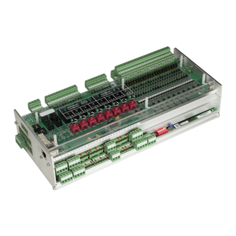
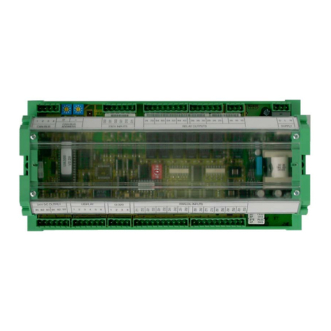
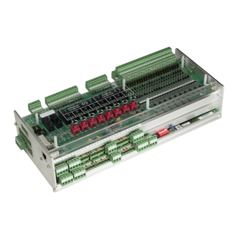
ECKELMANN Case Controller UA 4 E Series User manual

Firmware V3.13
21.04.2021
Docu 3.8
Operating instruction
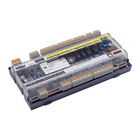
Case Controller UA 4xx E
Controller for electronic expansion valves (EEV)
The series UA 4xx E includes the following expansion stages: UA 400 E CC / UA 401 E CC / UA 410 E AC

Firmware V3.13
21.04.2021
2/466
Eckelmann AG
Business Unit Refrigeration and Building Automation
Berliner Straße 161
65205 Wiesbaden
Germany
Telephone +49 611 7103-700
Fax +49 611 7103-133
www.eckelmann.de
Board of Management: Dipl.-Ing. Peter Frankenbach (Spokesman),
Dipl.-Wirtsch.-Ing. Philipp Eckelmann, Dr.-Ing. Marco Münchhof
Chairman of the Supervisory Board: Hubertus G. Krossa
Deputy Chairman of the Supervisory Board: Dr.-Ing. Gerd Eckelmann
Registration court / registration number
District court Wiesbaden, HRB 12636
Before commissioning and use, please check that this is the latest version of the document. With the
publication of a new version of the documentation, all previous versions lose their validity. The current operating
manual and information such as data sheets, more detailed documentation and FAQs are available for you on-
line in E°EDP (Eckelmann ° Electronic Documentation Platform) at
www.eckelmann.de/elds
You reach all relevant documents for this component directly using the QR code:
https://edp.eckelmann.de/edp/lds/_s1nNBB45xE
Information on safety and connection instructions are described in detail in chapter ”Industrialsafety notes”.
Copyright: All rights to any use whatever, utilisation, further development, forwarding and creation of copies
remain with the Eckelmann AG company. In particular, neither the contract partners of Eckelmann AG nor other
users have the right to distribute or market the IT programs/program parts or modified or edited versions
without express written permission. To some extent, names of products/goods or designations are protected for
the respective manufacturer (registered trademarks etc.); in any case, no guarantee is assumed for their free
availability/permission to use them. The information provided in the description is given independently of any
existing patent protection or other third-party rights.
Errors and technical modifications are expressly reserved.

Firmware V3.13
21.04.2021
3/466
Table of Contents
1 Conventions..........................................................................................................................................10
1.1 Warning signs, symbols and text formatting used in this manual..................................................10
1.2 Explanation of text formatting ............................................................................................................11
2 Safety instructions ...............................................................................................................................12
2.1 Disclaimer in the event of non-compliance .......................................................................................13
2.2 Personnel requirements, requirements on staff ...............................................................................13
2.3 Intended use .........................................................................................................................................14
2.4 Five safety rules according to DGUV Regulation 3...........................................................................15
2.5 Electrostatic-sensitive components and control components (ESD).............................................16
2.5.1 ESD - Rules for handling and working ...................................................................................................16
2.6 Abbreviations used ..............................................................................................................................16
3 System Design of UA 4xx E.................................................................................................................17
3.1 Application............................................................................................................................................17
3.2 Hardware ...............................................................................................................................................18
4 Application of UA 4xx E .......................................................................................................................20
4.1 Versions ................................................................................................................................................20
4.2 Controller types....................................................................................................................................22
4.3 Updating firmware................................................................................................................................24
5 Function UA 4xx E................................................................................................................................25
5.1 Starting characteristics .......................................................................................................................25
5.1.1 First start- reset controller to factory settings .........................................................................................25
5.1.2 Restart - restart of the controller.............................................................................................................26
5.2 Temperature zones...............................................................................................................................27
5.3 CAN bus mode......................................................................................................................................29
5.4 Standalone operation...........................................................................................................................30
5.4.1 Standalone operation using evaporator inlet sensors ............................................................................30
5.4.2 Standalone operation using activated local pressure transmitter...........................................................31
5.5 Selection of the sensor type ...............................................................................................................32
5.5.1 Necessary and optional sensors ............................................................................................................33
5.6 Description of controller functions ....................................................................................................35
5.7 Cooling ..................................................................................................................................................36
5.7.1 Temperature control ...............................................................................................................................36
5.7.2 Control of the expansion valves .............................................................................................................37
5.7.2.1 Control of continuous motor expansion valves ......................................................................................40
5.7.2.2 Enable relays for motor expansion valves..............................................................................................41
5.7.3 Continuous temperature control by supply and return air temperature..................................................43

Firmware V3.13
21.04.2021
4/466
5.7.4 Continuous temperature control by coldroom sensor ............................................................................46
5.7.5 Continuous temperature monitoring using refrigerant temperature sensor............................................48
5.7.6 On-off control..........................................................................................................................................50
5.7.7 Superheat control ...................................................................................................................................51
5.7.8 Connection of pressure transmitters / humidity sensors ........................................................................54
5.7.9 Sending and receiving the analogue values via CAN bus .....................................................................55
5.7.10 Humidity control......................................................................................................................................56
5.7.11 Regulation according to tc / high pressure.............................................................................................58
5.7.12 Dynamic determination of the tc setpoint ...............................................................................................59
5.7.13 Fixed opening degree in the pump down / injection phase ....................................................................60
5.7.13.1 Fixed valve opening degree for servicing purposes...............................................................................60
5.7.14 Limiting the Opening Degree..................................................................................................................61
5.7.15 MOP function..........................................................................................................................................61
5.7.16 Run time limitation / continuous run monitoring of the regulation ..........................................................62
5.7.17 Forced cooling (except UK 100 E, KR 160 E)........................................................................................63
5.7.18 Heating circuit control.............................................................................................................................64
5.7.19 Emergency Op. ......................................................................................................................................65
5.7.20 Operation with up to four return air sensors - only UA 131 E LS ...........................................................66
5.8 Defrosting .............................................................................................................................................66
5.8.1 Typesofdefrosting–anoverview..........................................................................................................66
5.8.2 Defrosting in general ..............................................................................................................................67
5.8.3 Discharge gas defrosting (hot gas defrosting)........................................................................................73
5.8.4 Master/slavemode–defrostsynchronisationviaCANbus...................................................................74
5.8.5 Master/slavemode–defrostsynchronisationviawiring........................................................................77
5.8.5.1 Master-slave mode for the synchronisation of the zones of a single contr.............................................78
5.8.5.2 Master-slave mode for the synchronisation of several controllers .........................................................79
5.8.5.3 Necessary settings for the master / slave mode ....................................................................................80
5.8.5.4 Special features and constraints ............................................................................................................80
5.8.6 Consecutive defrost (CD) via CAN bus..................................................................................................82
5.9 Alarm relay............................................................................................................................................87
5.10 Fan control with case and coldroom controllers ..............................................................................87
5.10.1 Fan control on multidecks - controller type UA 121 E ............................................................................87
5.10.2 Fan control - controller type UA 131 E ...................................................................................................87
5.10.3 Fan control - controller type UA 131 E LS with enhanced fan control....................................................88
5.10.4 Fan control - controller type UA 141 E ...................................................................................................94
5.10.5 Fan control with coldroom controllers.....................................................................................................94
5.10.6 Coldroom with defrost heater (controller type UR 141 TE) ....................................................................96
5.10.7 Coldroom without defrost heater - controller type UR 141 NE ...............................................................97

Firmware V3.13
21.04.2021
5/466
5.10.8 Heating circuit - contr. type UR 141 TE, UR 141 NE in single-zone operation ......................................97
5.11 Digital inputs.........................................................................................................................................98
5.11.1 Setpoint toggle (day/night operation) .....................................................................................................99
5.11.2 Manual shutdown .................................................................................................................................100
5.11.3 Automatic on/off....................................................................................................................................100
5.11.4 Door contact .........................................................................................................................................102
5.11.5 Registration of external alarms (e.g. CO2 alarm).................................................................................103
5.12 Function of the analogue outputs 0..10 V. .......................................................................................104
5.13 Light control .......................................................................................................................................105
5.14 Frame and pane heater ......................................................................................................................107
5.15 Compressor control via consumers.................................................................................................109
5.16 Refrigeration point disabling ............................................................................................................110
5.17 E*COP+................................................................................................................................................110
5.18 Suction pressure shift .......................................................................................................................110
5.19 Emergency power operation ............................................................................................................. 111
5.20 BT 30 temperature display ................................................................................................................113
5.21 Operating data archiving ...................................................................................................................116
5.21.1 Temperature recording .........................................................................................................................116
5.21.2 Temperature recording to EU Regulation 37/2005...............................................................................116
5.21.3 Recording of t0, tc and relative humidity ..............................................................................................116
5.21.4 Recording of messages and alarms.....................................................................................................116
5.21.5 Actual value archiving with higher accuracy (15 sec) ..........................................................................117
6 Installation and Startup of UA 4xx E.................................................................................................118
6.1 Installation ..........................................................................................................................................118
6.1.1 DIN rail mounting of the controller for electronic valves.......................................................................118
6.1.1.1 Mounting on the DIN rail.......................................................................................................................119
6.1.1.2 Disassembling from the DIN rail...........................................................................................................121
6.1.2 Handling of the spring terminals...........................................................................................................122
6.2 Basic settings .....................................................................................................................................123
6.2.1 Setting the CAN bus address ...............................................................................................................124
6.2.2 Setting the controller type and other functions.....................................................................................125
6.3 Terminal assignment for 230 V AC power supply ...........................................................................129
6.3.1 Status LEDs .........................................................................................................................................130
6.4 Basic configuration of the controller ...............................................................................................132
6.4.1 Naming of the controller .......................................................................................................................139
6.5 Battery replacement...........................................................................................................................140
6.6 Firmware update.................................................................................................................................143
6.6.1 Requirements for firmware update.......................................................................................................144

Firmware V3.13
21.04.2021
6/466
6.6.2 Installing firmware update ....................................................................................................................146
6.6.2.1 Update for controller with 8-pole DIP switch ........................................................................................147
6.6.2.2 Update for controller with 9-pole DIP switch ........................................................................................151
6.6.3 Rectification of driver problems ............................................................................................................154
7 Pin and Terminal Assignments of UA 4xx E ....................................................................................156
7.1 Terminal diagram................................................................................................................................156
7.2 Terminal assignment of the 230 V AC power supply ......................................................................159
7.3 Terminal assignment of the 230 V AC relay outputs.......................................................................160
7.4 Mode of operation of the relay and transistor outputs...................................................................162
7.5 Terminal assignment of the 230 V AC digital inputs .......................................................................164
7.6 Terminal assignment of the 0..10 V analogue outputs ...................................................................166
7.7 Terminal assignment of the CAN bus terminals..............................................................................167
7.8 Terminal assignment of the 24 V DC transistor outputs ................................................................168
7.9 Terminal assignment of the DISPLAY interface...............................................................................169
7.10 Terminal assignment of the 4..20 mA analogue inputs...................................................................170
7.11 Terminal assignment of the analogue inputs for temperature sensors........................................171
7.11.1 Explanations for sensor positioning......................................................................................................173
7.11.2 Sensor identification .............................................................................................................................173
7.12 Assignment of the USB port .............................................................................................................174
7.13 Wiring of the master-slave function for defrost synchronisation .................................................175
8 Operation UA 4xx E ............................................................................................................................176
8.1 Operation possibilities.......................................................................................................................176
8.2 Local operation with a BT 300 x operator interface........................................................................177
8.2.1 Lock-down of the setpoint change........................................................................................................178
8.3 Remote control via a terminal ...........................................................................................................179
8.3.1 Menus and operating screens..............................................................................................................180
8.3.2 Calling the controller menu via remote control.....................................................................................183
8.3.2.1 System Centre......................................................................................................................................183
8.3.2.2 Store computer CI 3x00 / operator terminal AL 300 .............................................................................184
8.3.3 Deactivating the input lock-down..........................................................................................................185
8.3.3.1 System centre CI 4x00.. .......................................................................................................................185
8.3.3.2 Store computer CI 3x00 / operator terminal AL 300 .............................................................................185
8.3.4 Activating service mode .......................................................................................................................186
8.3.4.1 System centre Service-Mode ...............................................................................................................186
8.3.4.2 Store computer CI 3x00 - Service-Mode..............................................................................................186
9 Menu Structure UA 4xx E...................................................................................................................187
9.1 Controller type UA 121 E - menu tree...............................................................................................187
9.1.1 Main menu UA 121 E ...........................................................................................................................190

Firmware V3.13
21.04.2021
7/466
9.1.2 Menu 1 Actual Values UA 121 E...........................................................................................................191
9.1.3 Menu 2 Setpoints UA 121 E .................................................................................................................197
9.1.4 Menu 3 Clock UA 121 E .......................................................................................................................206
9.1.5 Menu 4 Messages UA 121 E................................................................................................................210
9.1.6 Menu 5 Archive UA 121 E ....................................................................................................................211
9.1.7 Menu 6 Configuration UA 121 E...........................................................................................................212
9.2 Contr. Type UA 131 E / UA 131 E LS - Menu tree .............................................................................228
9.2.1 Main Menu UA 131 E LS ......................................................................................................................231
9.2.2 Menu 1 Actual Values UA 131 E LS .....................................................................................................232
9.2.3 Menu 2 Setpoints UA 131 E LS............................................................................................................238
9.2.4 Menu 3 Clock UA 131 E LS..................................................................................................................248
9.2.5 Menu 4 Messages UA 131 E LS ..........................................................................................................252
9.2.6 Menu 5 Archive UA 131 E LS ...............................................................................................................253
9.2.7 Menu 6 Configuration UA 131 E LS .....................................................................................................254
9.3 Contr. Type UA 141 E - Menu tree .....................................................................................................268
9.3.1 Main Menu UA 141 E ...........................................................................................................................271
9.3.2 Menu 1 Actual Values UA 141 E...........................................................................................................272
9.3.3 Menu 2 Setpoints UA 141 E .................................................................................................................279
9.3.4 Menu 3 Clock UA 141 E .......................................................................................................................287
9.3.5 Menu 4 Messages UA 141 E................................................................................................................290
9.3.6 Menu 5 Archive UA 141 E ....................................................................................................................291
9.3.7 Menu 6 Configuration UA 141 E...........................................................................................................292
9.4 Contr. Type UR 141 NE - Menu tree ..................................................................................................305
9.4.1 Main Menu UR 141 NE ........................................................................................................................308
9.4.2 Menu 1 Actual Values UR 141 NE........................................................................................................309
9.4.3 Menu 2 Setpoints UR 141 NE ..............................................................................................................315
9.4.4 Menu 3 Clock UR 141 NE ....................................................................................................................324
9.4.5 Menu 4 Messages UR 141 NE.............................................................................................................327
9.4.6 Menu 5 Archive UR 141 NE .................................................................................................................328
9.4.7 Menu 6 Configuration UR 141 NE........................................................................................................329
9.5 Contr. Type UR 141 TE - Menu tree...................................................................................................345
9.5.1 Main Menu UR 141 TE.........................................................................................................................348
9.5.2 Menu 1 Actual Values UR 141 TE ........................................................................................................349
9.5.3 Menu 2 Setpoints UR 141 TE...............................................................................................................355
9.5.4 Menu 3 Clock UR 141 TE.....................................................................................................................366
9.5.5 Menu 4 Messages UR 141 TE .............................................................................................................369
9.5.6 Menu 5 Archive UR 141 TE..................................................................................................................370
9.5.7 Menu 6 Configuration UR 141 TE ........................................................................................................371

Firmware V3.13
21.04.2021
8/466
9.6 Contr. Type UK 100 E - Menu tree .....................................................................................................387
9.6.1 Main Menu UK 100 E ...........................................................................................................................389
9.6.2 Menu 1 Actual Values UK 100 E ..........................................................................................................390
9.6.3 Menu 2 Setpoints UK 100 E .................................................................................................................395
9.6.4 Menu 3 Clock UK 100 E .......................................................................................................................399
9.6.5 Menu 4 Messages UK 100 E................................................................................................................402
9.6.6 Menu 5 Archive UK 100 E ....................................................................................................................403
9.6.7 Menu 6 Configuration UK 100 E...........................................................................................................404
9.7 Controller type KR 160 E - menu tree...............................................................................................418
9.7.1 Main Menu KR 160 E ...........................................................................................................................420
9.7.2 Menu 1 Actual Values KR 160 E ..........................................................................................................421
9.7.3 Menu 2 Setpoints KR 160 E .................................................................................................................426
9.7.4 Menu 3 Clock KR 160 E .......................................................................................................................430
9.7.5 Menu 4 Messages KR 160 E................................................................................................................433
9.7.6 Menu 5 Archive KR 160 E ....................................................................................................................434
9.7.7 Menu 6 Configuration KR 160 E...........................................................................................................435
10 Decommissioning and disposal .......................................................................................................451
10.1 Decommissioning / Demounting ......................................................................................................451
10.2 Disposal ..............................................................................................................................................451
11 Alarms and messages UA 4xx E.......................................................................................................452
11.1 Alarm signaling and monitoring .......................................................................................................455
11.1.1 Coldroom door open alarm...................................................................................................................455
11.1.2 High or low temperature alarm .............................................................................................................455
11.1.3 Low temperature monitoring t0.............................................................................................................456
11.1.4 Alarm in the event of the absence of a defrost.....................................................................................456
11.1.5 Alarm in the event of the minimum permitted superheat being undershot...........................................457
11.1.6 Sensor break alarm ..............................................................................................................................457
11.1.7 Suppression of sensor break alarm during defrosting..........................................................................457
11.1.8 No required sensor alarm.....................................................................................................................458
11.1.9 Stall detect alarm..................................................................................................................................458
11.1.10 Implausible opening position alarm......................................................................................................458
11.1.11 Hardware alarm....................................................................................................................................458
11.2 Individual allocation of priorities ......................................................................................................459
11.3 Alarm routes .......................................................................................................................................460
11.4 Termination of alarm ..........................................................................................................................461
11.5 Messages ............................................................................................................................................461
11.5.1 Transient alarms and messages ..........................................................................................................461
11.5.2 Message log .........................................................................................................................................461

Firmware V3.13
21.04.2021
9/466
12 Technical Data of UA 4xx E ...............................................................................................................462
12.1 Electrical data .....................................................................................................................................462
12.2 Mechanical Data .................................................................................................................................464
12.3 Mechanical data of the temperature sensor L243 / 5K3A1.............................................................464
13 Order numbers and accessories of UA 4xx E .................................................................................465
13.1 Case Controller...................................................................................................................................465
13.2 Components .......................................................................................................................................465
14 INTERNE INCUDES - NICHT ZUR VERÖFFENTLICHUNG BESTIMMT...........................................466
14.1 Kältemittel EN - Menü 6-2-6 ...............................................................................................................466

Firmware V3.13
21.04.2021
10/466
•
•
•
•
•
1 Conventions
1.1 Warning signs, symbols and text formatting used in this manual
Explanation of the warning signs, symbols and text formatting used in this operating and service manual:
DANGER
WARNING
CAUTION
*IfanyofthesesymbolsDANGER/WARNING/CAUTION is recognized, the user must refer to the operating
manual in order to understand the type of potential HAZARD and the required actions for avoiding the
HAZARD. Carefully observe all health and safety instructions and use particular caution in these situations.
Failure to observe the DANGER/WARNING/CAUTION symbols will cause injury (in the worst case,
severe injury or death) and/or damage to property!
ATTENTION
NOTICE
DANGER
Instructions with this symbol and/or the signal word DANGER warn the user of situations that will
cause severe injury or death if the specified instructions are not observed! *
WARNING
Instructions with this symbol and/or the signal word WARNING warn the user of situations that may
cause severe injury or death if the specified instructions are not observed! *
CAUTION
Instructions with this symbol and/or the signal word CAUTION warn the user of situations that may
cause moderate or minor injury if the specified instructions are not observed! *
ATTENTION
Instructions with this symbol and/or the signal word ATTENTION warn the user of situations that may
cause damage to property if the specified instructions are not observed! The ATTENTION symbol
highlights guidelines and regulations, instructions and proper working procedures that must be
particularly observed in order to prevent damage to and destruction of components or malfunctioning.
Failure to observe the ATTENTION symbol will cause damage to property!
NOTICE
Instructions with this symbol and/or the signal word NOTICE provide tips and useful additional
information.

Firmware V3.13
21.04.2021
11/466
•
•
•
1.
2.
3.
4.
1.
2.
ELECTRIC SHOCK
Risk of fatal electric shock!
This symbol warns of danger from dangerous voltage with possible consequences such as severe injury and death. If this
symbol is seen, the user must refer to the operating manual in order to understand the type of potential HAZARD and the required
actions for avoiding the HAZARD. Carefully observe all health and safety instructions and use particular caution in these
situations.
Failure to observe the WARNING symbol will cause injury (in the worst case, severe injury or death) and/or damage to
property!
ESD - Electrostatic-sensitive components and control components
DISPOSAL
Potential negative impact on people and the environment due to non-environmentally friendly disposal.
The strike-through dustbin symbol indicates the duty to dispose of items properly. Do not dispose of this product with other
domestic waste. Please inform yourself about the local regulations for the separate disposal of electrical and electronic products.
The correct disposal of your old equipment protects people and the environment from possible negative impact.
Failure to observe the DISPOSAL symbol will cause damage to people and the environment!
1.2 Explanation of text formatting
Safety instructions or hazard warnings are composed of four elements:
Thesymbol with text (e.g. for DANGER),
a concise description of the hazard and
a description of the possible consequences.
Where applicable, a catalogue with measures for avoiding the hazard.
For example:
A general instruction consists of two elements:
Thesymbol with text (including NOTICE, if applicable) and
the text of the instruction:
For example:
Risk of destruction of the control component / controller!
Electronic components and control components (e.g. circuit boards) are sensitive to electrostatic charges. Circuit boards may only
be replaced when the power supply is disconnected. Always hold circuit boards by the edges. The guidelines for the handling of
electrostatic-sensitive components and control components must be observed at all times.
Failure to observe the ESD symbol will cause damage to property!
DANGER
Warning of dangerous electrical voltage! Risk of fatal electric shock!
Beware of external voltage at the digital inputs and outputs! Connections/plug connectors of the device
may only be plugged in, removed and/or wired when no voltage is present.
NOTICE
The current operating manual is available online from the E°EDP (Eckelmann ° Electronic
Documentation Platform) at www.eckelmann.de/elds.

Firmware V3.13
21.04.2021
12/466
•
•
•
•
•
•
•
•
•
•
•
•
2 Safety instructions
This operating manual is part of the device. It must be kept in the vicinity of the controller as well as for future
use so that it can be consulted when required. The operating manual must be available to the operating and
maintenance personnel at all times in order to avoid operating errors. The safety regulations, instructions and
information must be strictly observed and complied with. During repairs on the entire E*LDS system, the
accident prevention regulations and general safety regulations must be strictly complied with. Important
information (safety instructions and hazard warnings) are indicated by appropriate symbols, see chapter
Conventions. Follow these instructions in order to prevent accidents and danger to life and limb, as well as
damage to the E*LDS system!
Always observe the following information:
Workontheelectricalsystemmayonlybeperformedbyauthorised, skilled personnel (accordingtothe
definition of skilled persons in DIN/VDE 0105 and IEC364) while observing the applicable
- VDE regulations
-Localsafetyregulations
-Intended Use
-FivesafetyrulesaccordingtoDGUVRegulation3
-ESDmeasures
-Operatingmanuals
For safety reasons, the equipment must not be used for any applications other than described in the
operating manual and only for the intended use.
Before using the device, check whether it is suitable for your application with regard to its limit values.
The equipment must be installed in an electrically shielded area within the switch cabinet.
Before connecting the device, it must be checked whether the power supply is suitable for the device.
When using uncoded plug connectors, it is possible to connect them so that there is a danger to life and
limb! If this cannot be ruled out, coded plug connectors must be used.
Specified ambient conditions (e.g. humidity and temperature limits, see chapter Technical Data) must be
observed and complied with at all times to prevent malfunction.
Before switching on the device, check the correct wiring of the connections.
The device must never be operated without its housing. Before opening the housing, the device must be
de-energised.
Note the maximum load of the relay contacts, see chapter Technical Data.
Note that all supply lines from and to the device, particularly those of the CAN bus and Modbus, must be
shielded or installed sufficiently far away from live cables. This prevents faulty measurements and protects
the device against electrical interference via the analogue inputs. Connection in parallel of RC elements is
recommended for applications with critical environment.
Contact the supplier in the case of any malfunction.
DANGER
Warning of dangerous electrical voltage! Danger of electric shock!
Beware of external voltage at the digital inputs and outputs! Connections/plug connectors of the device
may only be plugged in, removed and/or wired when no voltage is present.

Firmware V3.13
21.04.2021
13/466
2.1 Disclaimer in the event of non-compliance
These operating instructions contain information on the commissioning, function, operation and maintenance
ofthecontrolsandoftheassociatedcomponents.
2.2 Personnel requirements, requirements on staff
Special technical knowledge is required for planning, programming, installation, putting into service and
maintenance work. This work may only be performed by skilled, specially trained personnel. The installation,
putting into service and maintenance personnel must have training that authorises them to perform
interventions in the system and the automation system. The planning and programming personnel must be
familiar with the safety concepts of automation technology. Working on electrical systems requires special
technical knowledge. Work on electrical systems may only be performed by instructed electrically skilled
persons or under the guidance or supervision of such persons. The applicable regulations (e.g. DIN EN 60204,
EN 50178, DGUV Regulation 3, DIN-VDE 0100/0113) must be observed. The operating personnel must be
instructed in how to handle the system / machine and the controller and must be familiar with the operating
instructions.
WARNING
Warning of damage to goods!
In our experience, the transmission of fault messages is not yet functional during the putting into
service (no internet connection, no telephone line installed, etc.). It is strongly recommended in such
cases to monitor the controller via the CAN bus using a system centre, a store computer or an operator
terminal and to enable the transmission of fault messages, for example using a GSM modem via a
mobile telephone system. In standalone operation, or as an alternative to monitoring via system
centre / store computer / operator terminal, an available alarm contact on the controller must be used
to enable the transmission of fault messages via a telephone network.
For more information, refer to E*LDS basics, safety instructions, CAN bus & Modbus.
Observance of these operating instructions is a prerequisite for safe and trouble-free operation.

Firmware V3.13
21.04.2021
14/466
2.3 Intended use
Thiscontrolsystemmayonlybeusedforthepurposeforwhichitisintended:TheUA401ECC/UA400E
CC/UA410EACcontrolsystemhasbeendesignedforuseascasecontrollerincommercialandindustrial
refrigerationsystemswiththeintendedfunctionalscopeasdescribedintheseoperatinginstructions,anditisto
be used under the environmental conditions in these instructions.
Read the safety instructions and the instructions for installation and putting into service, operation and
maintenance. THEN start the commissioning and/or operation of the machine / system.
The safety and functionality of the machine / system are only guaranteed for this intended application.
Never use the machine / system, its components, control components or parts for any other purpose.
The system must not be put into operation until conformity with the applicable EU Directives has been
established for the entire system.

Firmware V3.13
21.04.2021
15/466
•
•
•
•
•
•
•
2.4 Five safety rules according to DGUV Regulation 3
The following rules must be strictly observed!
1.Disconnect:The entire system to be worked on must be disconnected from the power supply at all poles.
2. Secure against reconnection: Attach information signs to the disconnected operating equipment stating:
What has been disconnected.
Reason for the disconnection.
Name of the person who made the disconnection.
Reconnection must be prevented using a suitable lock (e.g. padlock).
3. Prove dead (authorised skilled personnel only):
Check voltmeter just before use.
Prove dead on all poles at the disconnection point.
Prove dead on all poles at the work area.
4. Ground and short-circuit:Allelectricalpartsattheworkareamust be grounded and then short-
circuited.
5. Cover or block off adjacent live parts:Ifthereisliveequipmentadjacenttotheworkarea,itmustbe
covered using appropriate materials (e.g. insulation blankets / plates).
DANGER
Warning of dangerous electrical voltage! Warning of dangerous electrical voltage! Danger of
electric shock!
Beware of a possible external power supply! BEFORE connecting and disconnecting it must be
checked that no voltage is present at the controller! Connections/plug connectors of the device may
only be plugged in, removed and/or wired when no voltage is present.

Firmware V3.13
21.04.2021
16/466
•
•
•
•
•
•
•
•
•
•
•
•
•
•
•
•
•
•
•
2.5 Electrostatic-sensitive components and control components (ESD)
All electrostatic-sensitive components and control components (referred to as "ESD" below) are labelled with
the warning sign shown. Electrostatic charges arise from friction of insulating materials (e.g. floor covering,
items of clothing made of synthetic fibres etc.). Even small charges can result in damage to or destruction of
components. Such damage is not always immediately noticeable; in some cases, it does not lead to failure until
after a certain operating time.
2.5.1 ESD - Rules for handling and working
Transport and store ESDs only in the protective packaging provided.
Avoid materials that may produce electrostatic discharge, for example
Plastic containers and table tops
Synthetic fibre clothing
Plastic-soled shoes
Plastic file covers
Styrofoam packaging
Computer monitors, etc.
Preferably wear the following:
Cotton work clothes
ESD shoes with conductive soles or leather soles
Use the following:
Conductive flooring
ESD workstations equipped with suitable tools (grounded soldering guns, antistatic wrist straps, etc.)
Conductive ESD bags, conductive plastic containers, IC tubes or cartons lined with conductive foam
Containers and worktops made of wood, metal or conductive plastics or paper bags
2.6 Abbreviations used
DGUV Regulation 3 - Accident Prevention Regulation for Electrical Systems and Equipment
(previously: BGV A3-Employer’sLiabilityAssociationRegulationforOccupationalHealthandSafety)
DINDeutschesInstitutfürNormung e.V. (German Standardisation Institute)
EDP: Electronic Documentation Platform of Eckelmann AG
ESDElectrostatic-SensitiveDevice
ESDElectro-staticdischarge (ElectroSensitiveDevices)
IECInternationalElectricCommittee
VDEVerbandderElektrotechnikElektronik Informationstechnik e.V. (German Association for Electrical,
Electronic and Information Technologies)
ATTENTION
Risk of destruction of the control component / controller! Electronic components
and control components (e.g. circuit boards) are sensitive to electrostatic
charges.Therefore, the guidelines for handling electrostatic-sensitive components and
control components must be strictly observed.

Firmware V3.13
21.04.2021
17/466
3 System Design of UA 4xx E
Figure: UA 410 E AC - full configuration
3.1 Application
The use of the case controller UA 4xx E for electronic expansion valves provides decisive advantages thanks to
a reduced pressure difference between the high and low pressure sides, low superheat at the evaporator as
well as constant conditions for the goods and evaporator thanks to continuous regulation. The adaptive suction
pressure control generates further savings potential thanks to the load independent increase of the suction
pressure. A range of functions for cost and energy saving such as defrost on demand, latent heat utilisation,
intelligent fan control, enthalpy controlled frame heater and the continuous temperature control of the goods are
available with this case controller.
The case controller is suitable for control and monitoring in refrigerated cases and cold rooms for normal-
temperature refrigeration, low-temperature refrigeration (NT/LT), cascade controllers* or sub coolers*. The
appropriate controller type for multidecks, refrigerated counters, freezer islands, freezer rooms etc. can be set
easily using the DIP switches on the controller. The factory settings for the desired application that have been
tried and tested in practical use are then loaded.
The UA 4xx E case controller is available in the variants UA 401 E CC / UA 400 E CC / UA 410 E AC. The two
UA 400 E CC / UA 410 E AC case controllers support single-zone and two-zone operation. The UA 410 E AC
supports the controller types UK 100 E sub cooler and KR 160 E cascade controller. The UA 401 E CC variant
only supports one temperature zone.
UA 401 E CC UA 400 E CC * UA 410 E AC
(complete design)
Single-zone operation Single-zone operation
Two-zone operation
Single-zone operation
Two-zone operation
Standalone operation
- - Sub cooler and cascade controller
For more details, see chapters Hardware, Versions,Controller types and Temperature zones.

Firmware V3.13
21.04.2021
18/466
•
•
In order to fully utilise its performance features, the case controller is typically connected to the CAN bus, using
which it communicates with further control and monitoring components across the entire network. Intelligent
data exchange with the following system components takes place via the CAN bus:
System centre / store computer: Archiving of the operating data and alarm and message management,
connection to LDSWin for analysis, configuration and evaluation
Pack controllers: Adaptive control in connection with the associated pack controller, consumer lock
(emergency function in the event of pack failure)
3.2 Hardware
The case controller is housed in a plastic casing for DIN rail mounting and does not require any further optional
extension modules. Up to 99 case controllers can be used in the E*LDS system. If required, a BT 300 x
Operator Interface and up to 4 BT 30 Temperature Displays can be connected. For the direct parametrisation of
the case controller via LDSWin, for carrying out a firmware update of the case controller or for the
parametrisation of system components via CAN bus using LDSWin, the controller can be connected to a
notebook or a PC via the USB port. The following diagram illustrates the system architecture of the UA 410 E
AC case controller (complete design):
The range of functions described in this operating manual refers to the complete design.

Firmware V3.13
21.04.2021
19/466
•
•
•
Mounting variants UA 401 E CC UA 400 E CC UA 410 E AC
(complete design)
= terminals not mounted
For details, see chapter Terminal diagram.
Interfaces
CANbus,communicationintheE•LDSsystem • • •
DISPLAY - Connection for BT 300 x operator interface and up to
four BT 30 temperature displays
• • •
USB
For direct parametrisation of the case controller via
LDSWin or
For carrying out a firmware update of the case controller
or
For parametrisation of system components via CAN bus
using LDSWin
• • •
Inputs
Digital inputs
230 V AC, floating output
4 4 4
Analogue inputs
for temperature sensors (2-wire, NTC)
5 10 10
Analogue inputs 4..20 mA
, e.g. for the connection of pressure transmitters or a humidity
sensor
- - 2
Outputs
Semiconductor relay (SSR) 230 V AC / 1 A (SSR = Solid State
Relay)
normally open contact, for controlling electronic expansion valves)
1 2 2
2 x transistor outputs
24 V DC / 50 mA (Light control, Frame and pane heater)
2 2 2
Relay outputs
230 V AC / 6 A (normally open contact)
4 4 4
Relay output (Alarm relay)
230 V AC / 6 A (changeover contact)
- 1 1
Analogue outputs 0..10 V DC
e.g. for Control of continuous motor expansion valves
- - 2
Real-time clock
RTC, with power reserve, lithium cell (battery) - - •
Details about the distinguishing features of the controllers are explained in chapter Versions.The
application areas of the case controller are described in more detail in chapter Controller types. The
connection and terminal assignment are described in chapter Pin and Terminal Assignments of UA 4xx
E.

Firmware V3.13
21.04.2021
20/466
•
•
4 Application of UA 4xx E
4.1 Versions
Distinguishing features of the UA 4xx E case controller for DIN rail mounting; for further details, see
chapter Hardware.
UA 401 E CC UA 400 E CC * UA 410 E AC *
(complete design)
Mounting variants
= terminals not mounted
For details, see chapter Terminal
diagram.
Supported Temperature zones Single-zone operation Single-zone operation
Two-zone operation
Single-zone operation
Two-zone operation
Standalone operation
For integration in the CAN bus of the
E*LDS system
•• •
Number of temperature sensors 5 10 10
Alarm relay -•1
Analogue inputs 4..20 mA -- 2
Analogue outputs 0..10 V -- 2
Integrated real-time clock,
power reserve using battery (lithium cell)
--•
Integrated archive memory for data
recording
--•
Sub cooler UK 100 E / cascade
controller KR 160 E,
for details, see chapter Controller types.
- - •
Replacement controller for UA 300 E AC --•
Abbreviations used
CCstandsforCAN bus and Cabinet / DIN rail mounting(C=withCANbusandC=DINrailmounting).
ACstandsforAll in one and Cabinet / DIN rail mounting(All=withCANbusandreal-timeclockandC=
DIN rail mounting).
Table of contents
Other ECKELMANN Controllers manuals
ECKELMANN
ECKELMANN VS 3015 C User manual
ECKELMANN
ECKELMANN UA 410 L Case Controller User manual
ECKELMANN
ECKELMANN UA 400 User manual
ECKELMANN
ECKELMANN VS 300 User manual
ECKELMANN
ECKELMANN VS 3000 BS User manual
ECKELMANN
ECKELMANN UA 410 D User manual
ECKELMANN
ECKELMANN UA 410 L User manual

ECKELMANN
ECKELMANN WRG 3010 E User manual
ECKELMANN
ECKELMANN VS 3000 User manual
ECKELMANN
ECKELMANN UA 412 S User manual
