INSTALLATION INSTRUCTIONS
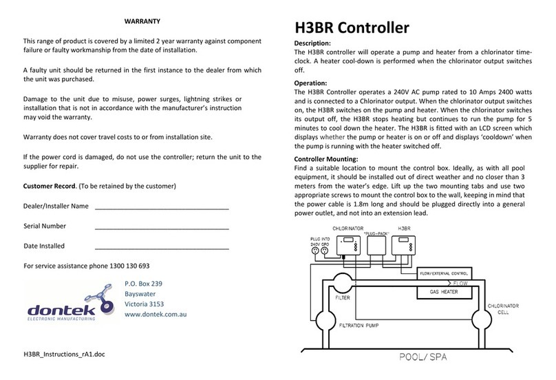
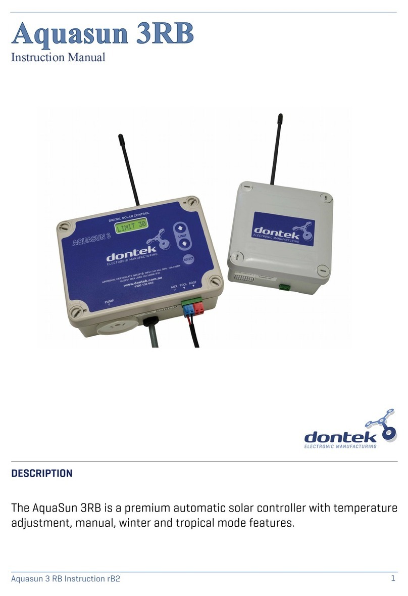
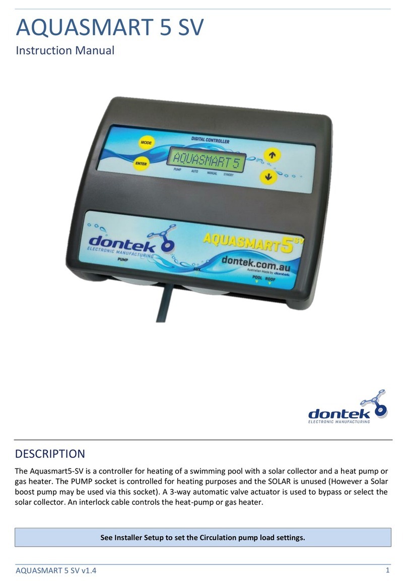
CONTROLLER: Find a suitable location to ount the control box*radio note. The controller should be
installed out of direct weather and no closer than 3 eters fro the water’s edge. Lift up the two
ounting tabs and use two appropriate screws to ount the control box to the wall, keeping in ind
that the power cable is 1.8 long and should be plugged directly into a general power outlet, not into
an extension lead. Do not drill through the box.
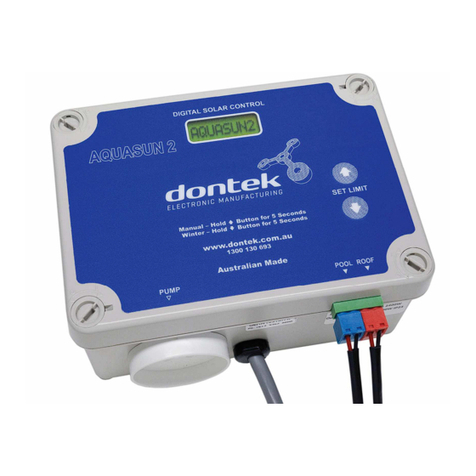
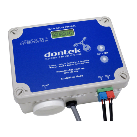
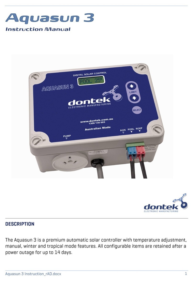
SOLAR PUMP: The solar pu p plugs into the left side 240Vac socket arked as PUMP. Note that the
solar pu p can only operate when the FLOW switch detects water flow.
FLOW SWITCH: The Flow switch is fitted in the PVC pipe after the filter and before the take-off T; it
ust be ounted at the top of the pipe with the arrow atching the direction of water flow. If a
pressure switch is used it ust be ounted before the filter.
TEMPERATURE SENSOR: The pool te perature sensor ust be fitted into the suction line of the
filtration pu p, as close to the pool as practical, preferably in a position out of direct sunlight. It is
reco ended that a 14.5 hole be drilled in the PVC pipe, this can be carried out using a Dontek
PD01 grinding drill or a s all pilot hole can be drilled and a 14.0 drill-bit used spinning in a
counter clockwise direction to ini ize the chance of shattering pipe. Insert the gro et into the
pipe and gently push in the blue sensor barb. The blue sensor plug is to be fitted to the plug socket
arked POOL, in so e cases there is so e benefit to cable tie 30c of wire fro the pool
te perature sensor to the pipe and insulate this section (so e a bient differences can travel up the
tinned copper wire and affect the sensor reading).
All temperature sensor cables must NOT be run parallel to po er cables and should never
be cable tied to po er cables. All cable run lengths should be less than 50 if possible. Cable ties
should be used to fasten the sensor cable to the cold water inlet pipe aking sure that the ties are
approxi ately 10 fro PVC fittings. Cable ties should be tightened only fir , over tightening can
cause breaks in the outer PVC if not careful. If the cable is to be run under ground a conduit ust be
used to protect the wire and there is to be no cable joins within, conduit ends must be sealed to
prevent water ingress.
Any excess cable should be removed and re-fitted ensuring that the ire ends are tinned
ith solder.
REMOTE TEMPERATURE ROOF SENSOR:
The roof te perature sensor ust be fitted into a s all piece of solar collector or equivalent and
attached to the roof. The best location is within an ar s length of the gutters edge of the house or
shed as long as the sensor end is not shaded and is on a roof of si ilar aspect of the ain collector. It
must not be fitted on top of the solar collector or fitted to high points on the roof like Ridge Capping
as false readings will be detected.
This unit has been designed to eli inate the need to run a te perature sensor cable fro the solar
controller to the roof; this is replaced by a solar powered trans itter that trans its the roof
te perature. The roof te perature sensor cable is connected on the inside of the radio re ote
te perature trans itter in a screw in socket. Test for site suitability (*radio note) then ount the radio
re ote te perature trans itter on the gutter ensuring the solar panel (PV) faces north and the
antenna points up (Vertical), if the antenna faces down then water ay enter the box through the
power entry / sensor entry hole and void the warranty.
*RADIO NOTE: RADIO TRANSMITTER SPECIAL CONSIDERATIONS:
Do not per anently fix the radio trans itter until good reception is achievable (See site test); do not
ount the Aquasun 3 in a position where reception of radio signals ay be difficult, avoid ounting
near other electrical equip ent (try a site test with a FM radio or Mobile phone).
The range is 100 with no obstructions and with no interference fro other trans itters or sources of
electrical noise. Trans ission ay not occur through objects such as steel, alu iniu , re-enforced
concrete and large bodies of water (e.g. pu p roo under a pool). Line of sight is the ideal situation
but not always possible, the antennas should always re ain vertical. Echo cancellation or ghosting
ay occur, which will prevent the signal being received reliably. If the Aquasun 3 is to be installed in a
etal shed there ay be reception issues and the controller ay need to be optioned with a re ote
antenna or oved outside.
