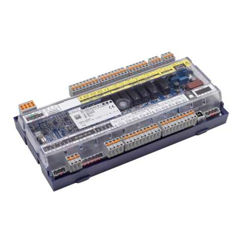
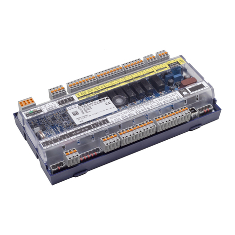
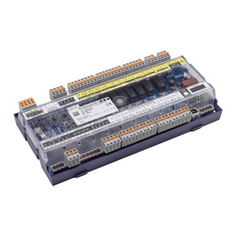
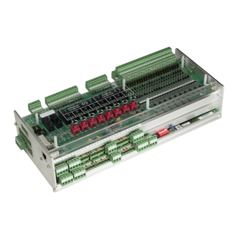
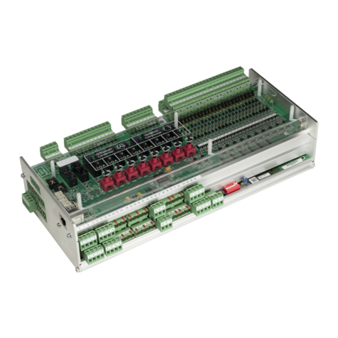
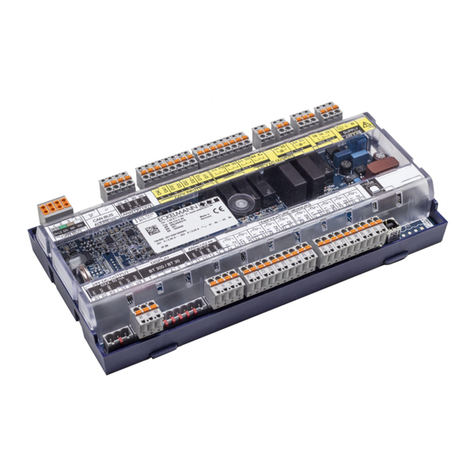
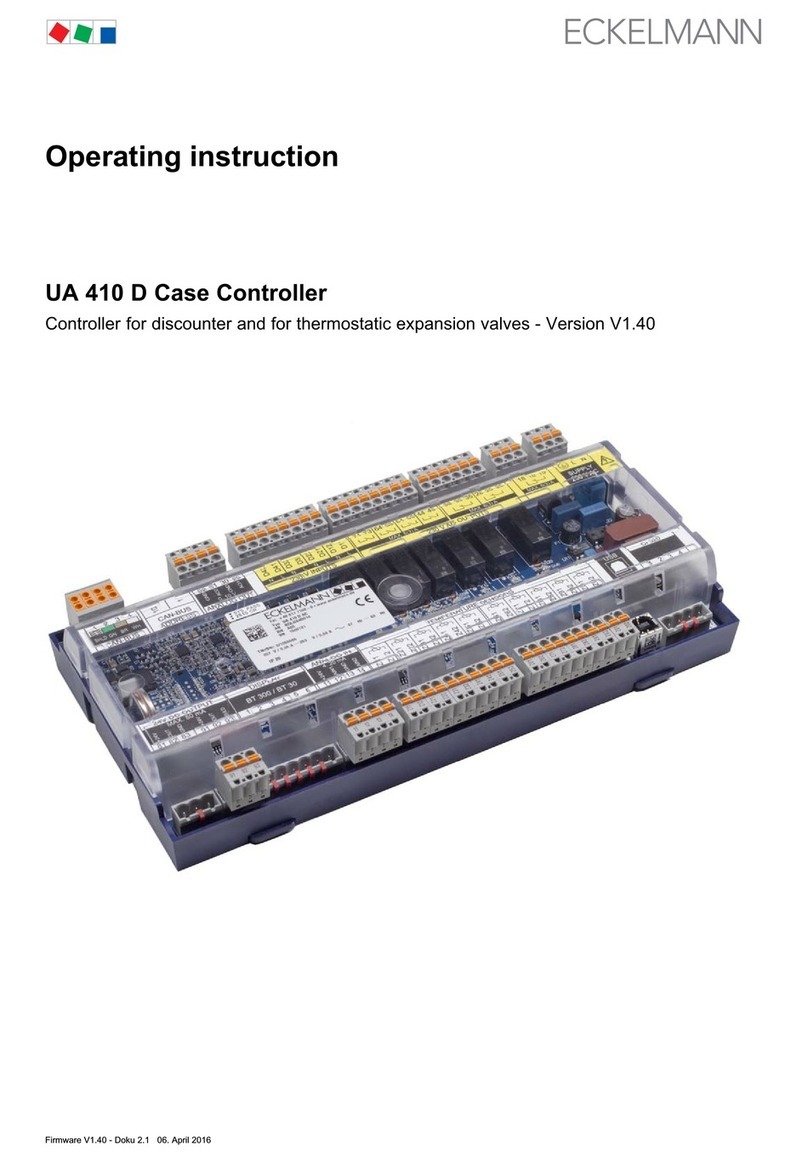
ECKELMANN VS 3015 C User manual

14.01.2019 Version V1.05 - January 2019
Operating instruction
VS 3015 C Pack Controller
VS 3015 C Pack Controller - Version V1.05

14.01.2019 2/185
Eckelmann AG
Business Unit Refrigeration and Building Automation
Berliner Straße 161
65205 Wiesbaden
Germany
Telephone +49 611 7103-700
Fax +49 611 7103-133
www.eckelmann.de
Board of Management: Dipl.-Ing. Peter Frankenbach (Spokesman),
Dipl.-Wirtsch.-Ing. Philipp Eckelmann, Dr.-Ing. Marco Münchhof, Dr.-Ing. Frank Uhlemann
Chairman of the Supervisory Board: Hubertus G. Krossa
Deputy Chairman of the Supervisory Board: Dr.-Ing. Gerd Eckelmann
Registration court / registration number
District court Wiesbaden, HRB 12636
Before commissioning and use, please check that this is the latest version of the document. With the
publication of a new version of the documentation, all previous versions lose their validity.
Information on safety and connection instructions are described in detail in chapter ”Industrial safety notes”.
Copyright: All rights to any use whatever, utilisation, further development, forwarding and creation of copies
remain with the Eckelmann AG company. In particular, neither the contract partners of Eckelmann AG nor other
users have the right to distribute or market the IT programs/program parts or modified or edited versions
without express written permission. To some extent, names of products/goods or designations are protected for
the respective manufacturer (registered trademarks etc.); in any case, no guarantee is assumed for their free
availability/permission to use them. The information provided in the description is given independently of any
existing patent protection or other third-party rights.
Errors and technical modifications are expressly reserved.

14.01.2019 3/185
Table of Contents
1 Conventions........................................................................................................................................... 9
1.1 Explanation of "General Instructions" ................................................................................................ 9
1.2 Explanation of "Safety Instructions and Hazard Warnings" ............................................................. 9
1.3 Warning Signs and Symbols Used ...................................................................................................... 9
2 Safety instructions .............................................................................................................................. 11
2.1 Exclusion of liability for non-observance ......................................................................................... 12
2.2 Requirements for the personnel ........................................................................................................ 12
2.3 Intended Use........................................................................................................................................ 12
2.4 Five safety rules according to BGV A3 ............................................................................................. 13
2.5 Electrostatic sensitive components and control components (ESD) ............................................ 14
2.5.1 ESD - guidelines for handling................................................................................................................ 14
2.6 Abbreviations used ............................................................................................................................. 15
3 System design VS 3015 C................................................................................................................... 16
4 Application of VS 3015 C .................................................................................................................... 17
5 Function of VS 3015 C ........................................................................................................................ 19
5.1 Starting characteristics ...................................................................................................................... 19
5.1.1 First start ............................................................................................................................................... 19
5.1.2 Restart................................................................................................................................................... 19
5.2 System Configuration ......................................................................................................................... 19
5.3 Configuration of the pressure transmitters ...................................................................................... 20
5.3.1 Low pressure transmitter Z2 (LP-Z2) .................................................................................................... 21
5.4 Low-pressure Regulation ................................................................................................................... 21
5.4.1 Control algorithm for LP control............................................................................................................. 22
5.4.2 Control algorithm with LP step controller............................................................................................... 22
Neutral zone with compressor step control ........................................................................................... 22
Compressor switching times for compressor step regulation................................................................ 23
5.4.3 Control algorithm with LP combined control.......................................................................................... 23
Switching on / switching off of fixed-speed compressors...................................................................... 24
Loading / unloading of fixed-speed compressors during operation with capacity-controlled
compressors.......................................................................................................................................... 24
Speed increase for purpose of oil lubrication ........................................................................................ 27
5.4.4 Setpoint shift.......................................................................................................................................... 27
Setpoint shift via room temperature / jump to end of the metadata ...................................................... 27
Setpoint shift - demand-dependent via consumer................................................................................. 28
Setpoint shift via CAN bus..................................................................................................................... 28
Setpoint shift via external analogue signal............................................................................................ 29

14.01.2019 4/185
Setpoint shift via humidity sensor.......................................................................................................... 29
5.4.5 Base load rotation ................................................................................................................................. 30
Base load rotation for speed controlled compressors ........................................................................... 30
5.4.6 Load shedding....................................................................................................................................... 31
5.4.7 Emergency power mode ....................................................................................................................... 33
5.5 High-pressure regulation.................................................................................................................... 33
5.5.1 Control of high pressure control valve................................................................................................... 34
Neutral zone HP control ........................................................................................................................ 34
HP valve control for stopped compressors............................................................................................ 34
Limitation of the HP valve opening degree by the medium pressure.................................................... 34
5.5.2 High pressure setpoint calculation ........................................................................................................ 34
HP regulation setpoint calculation in normal operation ......................................................................... 35
HD regulation setpoint calculation in HRC mode .................................................................................. 35
5.6 Gas cooler outlet temperature regulation......................................................................................... 35
5.6.1 Neutral zone fan control ........................................................................................................................ 36
5.6.2 Control algorithm for fan control............................................................................................................ 36
5.6.3 Control algorithm with step controller.................................................................................................... 36
5.6.4 Switching modes for step control .......................................................................................................... 37
5.6.5 Regulation of the fan speed with continuous control............................................................................. 39
5.6.6 Control algorithm for parallel combined control type of control ............................................................. 39
5.6.7 Control algorithm for stages combined control type of control .............................................................. 41
5.6.8 Gas cooler package with integrated outdoor evaporator in bypass operation ...................................... 42
5.6.9 Gas cooler package with ebmpapst fans .............................................................................................. 43
5.6.10 Setpoint calculation tG .......................................................................................................................... 48
Setpoint calculation in normal operation ............................................................................................... 48
Setpoint calculation in HRC mode......................................................................................................... 49
5.6.11 Switching times of the fans.................................................................................................................... 49
5.6.12 Setpoint increase tG.............................................................................................................................. 50
5.6.13 Protection and base load rotation of the fan motors ............................................................................. 50
5.7 Medium pressure regulation .............................................................................................................. 51
5.7.1 Regulation ............................................................................................................................................. 51
5.7.2 Medium pressure shift / monitoring of minimum superheat .................................................................. 51
5.7.3 Setpoint reduction above medium pressure.......................................................................................... 54
5.7.4 Medium pressure maintenance............................................................................................................. 54
Medium pressure maintenance via pressure maintenance valve ......................................................... 54
Medium pressure maintenance by opening the HP valve..................................................................... 55
5.8 ECO operation ..................................................................................................................................... 55
5.8.1 Control by a VS 3015 C......................................................................................................................... 56

14.01.2019 5/185
5.8.2 Control by a VS 3015 C and a separate pack controller ....................................................................... 58
5.9 LT compressor in booster operation................................................................................................. 60
5.10 Regulation of the minimum superheat using a hot gas bypass valve........................................... 62
5.11 Regulation of the maximum superheat using the suction gas injection valve ............................. 63
5.12 Monitoring............................................................................................................................................ 64
5.12.1 Safety chain........................................................................................................................................... 64
Monitoring of differential oil pressure switch / compressor high pressure limiter.................................. 65
Monitoring of the compressor motor overload cut-out........................................................................... 65
5.12.2 Cylinder head temperature monitoring.................................................................................................. 66
5.12.3 Low pressure monitoring ....................................................................................................................... 68
5.12.4 High pressure monitoring ...................................................................................................................... 68
5.12.5 Monitoring of the medium pressure....................................................................................................... 70
5.12.6 Monitoring of the medium pressure valve ............................................................................................. 70
5.12.7 Monitoring of the fan motor overload cut-out......................................................................................... 70
5.12.8 Monitoring of the fan speed controller................................................................................................... 71
5.12.9 Monitoring of the compressor speed controller ..................................................................................... 71
5.12.10 External alarm monitoring ..................................................................................................................... 73
5.12.11 Monitoring of the switching frequency................................................................................................... 74
5.12.12 Refrigerant monitoring........................................................................................................................... 75
5.12.13 Monitoring of the fast unload / External Off........................................................................................... 75
5.12.14 Rupture disk monitoring ........................................................................................................................ 75
5.13 Setpoint switching .............................................................................................................................. 76
5.14 Ambient data for the setpoint switching........................................................................................... 76
5.15 Consumer lockout............................................................................................................................... 76
5.16 Spray system control.......................................................................................................................... 77
5.17 COP monitoring ................................................................................................................................... 79
5.18 COP optimisation ................................................................................................................................ 80
5.19 Operating data and archiving............................................................................................................. 80
5.19.1 Operating hours of compressors and fans ............................................................................................ 80
5.19.2 Daily run times, switching pulses and switch-on rates .......................................................................... 80
5.20 Capacity-controlled compressors ..................................................................................................... 80
5.21 Oil balancing........................................................................................................................................ 82
6 Installation and start-up of VS 3015 C............................................................................................... 84
6.1 DIN rail mounting ................................................................................................................................ 84
6.2 Requirements for the activation of NT CO2 operation (transcritical) ............................................ 84
6.3 Basic hardware settings ..................................................................................................................... 85
6.3.1 SIOX extension module - for DIN rail mounting .................................................................................... 86
Connection of the SIOX modules to the pack controller ....................................................................... 87

14.01.2019 6/185
SIOX - Status LEDs............................................................................................................................... 88
6.3.2 Basic settings with S1 ........................................................................................................................... 88
6.3.3 Setting the CAN bus address with S2 ................................................................................................... 90
6.3.4 Setting of the interface RS485/TTY using jumper J1 ............................................................................ 91
6.3.5 Setting of the interface of the internal SIOX using jumper J2 ............................................................... 92
6.3.6 Configuration of the analogue inputs and outputs at the factory........................................................... 92
6.3.7 Power supply......................................................................................................................................... 93
Status LEDs .......................................................................................................................................... 93
6.4 Basic parameter settings.................................................................................................................... 94
6.5 Start-up of speed-controlled condenser fans / compressors......................................................... 95
6.5.1 Procedure for the start-up of a system.................................................................................................. 96
6.6 Commissioning fan control via Modbus ........................................................................................... 98
6.7 Battery replacement.......................................................................................................................... 100
6.8 Firmware Update ............................................................................................................................... 100
6.8.1 Installation of the update software on the PC...................................................................................... 101
6.8.2 Update of the current firmware............................................................................................................ 102
7 Connection and terminal assignment of VS 3015 C ...................................................................... 106
7.1 Connector pin assignments ............................................................................................................. 106
7.1.1 Connector pin assignments for the VS 3015 C basic module............................................................. 106
7.1.2 Pin assignments for SIOX extension module...................................................................................... 107
7.2 Terminal diagrams for basic module and SIOX.............................................................................. 107
7.2.1 Assignment of the 230 V AC power supply ......................................................................................... 108
7.2.2 Terminal assignment of the digital inputs - 230 V AC.......................................................................... 109
7.2.3 Terminal assignment of the relay outputs - 230 V AC ......................................................................... 112
7.2.4 Assignment of the analogue inputs ..................................................................................................... 114
7.2.5 Terminal assignment of the analogue outputs..................................................................................... 116
7.2.6 CAN bus, SIOX and Modbus (ebmpapst fans) terminal assignment .................................................. 118
8 Operating modes of VS 3015 C ........................................................................................................ 120
8.1 Manual / automatic emergency mode selection............................................................................. 120
8.2 Service Mode ..................................................................................................................................... 121
8.3 Display of the operating states ........................................................................................................ 121
9 Operation of VS 3015 C..................................................................................................................... 123
9.1 Operation possibilities...................................................................................................................... 123
9.2 Remote control using a terminal ..................................................................................................... 123
9.2.1 Menus and operating screens............................................................................................................. 125
9.2.2 Call controller menu using remote operation....................................................................................... 128
CI 4x00 System Centre - Remote control............................................................................................ 128
CI 3x00 store computer / AL 300 operator terminal - remote control .................................................. 129

14.01.2019 7/185
9.2.3 Deactivating the input lock .................................................................................................................. 129
CI 4x00 system centre - login and logout............................................................................................ 130
CI 3x00 store computer / AL 300 operator terminal - unlock ............................................................... 130
9.2.4 Activating service mode ...................................................................................................................... 130
CI 4x00 system centre service mode .................................................................................................. 131
CI 3x00 store computer - service mode .............................................................................................. 131
10 Menu structure of VS 3015 C............................................................................................................ 132
10.1 Menu tree ........................................................................................................................................... 132
10.1.1 Menu 0 Main menu.............................................................................................................................. 134
10.1.2 Menu 1 Summary ................................................................................................................................ 134
10.1.3 Menu 2 Actual values .......................................................................................................................... 135
10.1.4 Menu 3 Setpoints ................................................................................................................................ 139
10.1.5 Menu 4 Clock ...................................................................................................................................... 169
10.1.6 Menu 5 Messages ............................................................................................................................... 170
10.1.7 Menu 6 Operating data........................................................................................................................ 170
10.1.8 Menu 7 Basic settings ......................................................................................................................... 173
10.1.9 Menu 8 Service Mode ......................................................................................................................... 173
11 Decommissioning and disposal ...................................................................................................... 175
11.1 Decommissioning / Dismantling...................................................................................................... 175
11.2 Disposal ............................................................................................................................................. 175
12 Alarms and messages VS 3015 C .................................................................................................... 176
12.1 Message system................................................................................................................................ 176
12.2 Structure of the messages ............................................................................................................... 176
12.2.1 Automatic Prioritisation........................................................................................................................ 177
12.3 Overview of all alarms and messages............................................................................................. 177
13 Technical Data VS 3015 C / SIOX ..................................................................................................... 182
13.1 Electrical Data VS 3015 C / SIOX...................................................................................................... 182
13.2 Mechanical Data VS 3015 C.............................................................................................................. 184
13.3 Mechanical Data SIOX Extension Module With manual control switch....................................... 185

14.01.2019 8/185

14.01.2019 9/185
1 Conventions
1.1 Explanation of "General Instructions"
A general instruction consists of two elements:
1. A pictogram of a hand at the side of the page as well as
2. The actual text:
For example:
1.2 Explanation of "Safety Instructions and Hazard Warnings"
Safety instructions or hazard warnings are composed of four elements:
1. The pictogram (warning sign / symbol) at the edge of the page.
2. A short, concise description of the danger.
3. A description of the possible consequences.
4. A catalogue with prevention measures.
For example:
The warning signs and symbols used for the safety instructions and hazard warnings in this documentation are
described in detail on the following page.
1.3 Warning Signs and Symbols Used
Explanation of the warning signs and symbols used for the safety instructions and hazard warnings in this
documentation:
Attention symbol - general hazard warning
Failure to observe the attention symbol can result in personal injury (in extreme cases serious injuries or death)
and/or material damage!
Further information for the enclosure protection of the device is contained in the chapter Technical
Data VS 3015 C / SIOX.
Warning of dangerous electrical voltage! Danger of electric shock! BEFORE connecting and
disconnecting, it must be checked that no voltage is present at the 230 V AC relay outputs!
1. Hazard warning
The attention symbol indicates all safety instructions in this operating and service manual which
result in danger to life and limb if not observed. Carefully comply with the work safety
instructions and proceed with particular caution in these cases.
2. Attention
The attention symbol highlights guidelines and regulations, instructions and correct working
procedures that must be particularly observed in order to prevent damage to and destruction of
LDS components or malfunctioning (for example to prevent stock loss).

14.01.2019 10/185
Voltage symbol - warns about hazardous electrical voltage
ESD symbol - warning of electrostatic sensitive components and control components
This symbol indicates electrostatic sensitive components and assemblies, for details see chapter
Electrostatic sensitive components and control components (ESD)
Note symbol
Battery disposal symbol
Never dispose of this product with other domestic waste.
Please inform yourself about the local regulations for the separated disposal of electrical and electronic products.
The correct disposal of your old equipment protects the environment and people against possible negative consequences.
Further information can be found in the chapter "Decommissioning and Disposal".
This work safety symbol warns about hazards from dangerous electrical voltage with possible
consequences of serious injuries and death.
The note symbol highlights usage tips and other useful information contained in this operating and
service manual.

14.01.2019 11/185
2 Safety instructions
•This operating manual is part of the equipment. It must be kept in the vicinity of the controller as well as
for future use so that it can be consulted when required. The operating manual must be available for the
operating and maintenance personnel at any time for the avoidance of operating errors, see chapter
Erklärung zu den 'Sicherheits- und Gefahrenhinweisen'.
•For safety reasons, the equipment must not be used for any applications other than described in the
operating manual and only for the intended use, see chapter Warning Signs and Symbols Used.
•Before using the device, check whether it is suitable for your application with regard to its limit values.
•Before connecting the device, it must be checked whether the power supply is suitable for the device.
•When using uncoded plug connectors, it is possible to connect them so that there is a danger to life and
limb! If this cannot be ruled out, coded plug connectors must be used.
•Specified environmental conditions (e.g. humidity and temperature limits) must be observed and
complied with. Otherwise, malfunctions are possible (see chapter Technische Daten VS 3010 C / SIOX).
•Before switching on the device, check correct wiring of the connections.
•The device must never be operated without its case. Before opening the case, the device must be
disconnected from the power supply.
•Note the maximum load of the relay contacts (see chapter Technische Daten VS 3010 C / SIOX).
•Contact the supplier in the case of any malfunction.
The safety regulations, instructions and information described in this chapter must be strictly observed
and complied with. During repairs on the entire E*LDS system, the accident prevention regulations and
general safety regulations must be strictly complied with. Important information (safety instructions and
hazard warnings) are indicated by appropriate symbols (see the chapter Conventions). Follow these
instructions in order to prevent accidents and danger to life and limb, as well as damage to the E*LDS
system.
Warning of dangerous electrical voltage! Danger of electric shock! Beware of external voltage at
the digital inputs and outputs! All device connections/male connectors must only be plugged in,
unplugged and/or wired when no voltage is present.
1. According to experience, transmission of alarms is not yet functional during commissioning (no
telephone line laid etc.). It is strongly recommended in such cases to monitor the controller via
the CAN bus using a system centre or an operator terminal and to enable transmission of alarms
using a GSM modem via a mobile telephone system. In standalone operation, or as an
alternative to monitoring with system centre / operator terminal, an available alarm contact on
the controller must be used to realise transmission of alarms via a telephone network.
2. After the setting up of transmission of alarms or alarm signalling, this must be tested and
checked for its function.
For further information about the CAN bus, see the operating instruction "Basic and General Safety and
Connection Notes".

14.01.2019 12/185
2.1 Exclusion of liability for non-observance
This operating manual contains information about the commissioning, function, operation and maintenance of
the controller and the associated components.
2.2 Requirements for the personnel
Special technical knowledge is required for planning, programming, installation, putting into service and
maintenance work. This work may only be performed by trained or specially trained personnel. The installation,
commissioning and maintenance personnel must have training which authorises interventions in the system
and the automation system. The planning and programming personnel must be familiar with the safety
concepts of automation technology. Specialist knowledge is required for work on electrical systems. Work on
electrical systems may only be carried out by qualified electricians or persons under their guidance or
supervision. In doing so, the respective applicable regulations (e.g. DIN EN 60204, EN 50178, BGV A3, DIN
VDE 0100/0113) must be observed. The operating personnel must be instructed in handling the system /
machine and the controller and must be familiar with the operating instructions.
2.3 Intended Use
This controller has been designed exclusively for the intended use:
The VS 3015 C controller is designed for use as pack controller in commercial and industrial refrigeration
facilities in accordance with the scope of functions and in accordance with the environmental conditions
described in this operating manual.
Note the safety instructions and the instructions for installation and start-up, operation and maintenance. Start
the commissioning and/or operation of the machine / system AFTERWARDS.
The safety and the function of the machine / system are only fulfilled with this intended use.
Never use the machine / system, its components, control components or parts for any other purpose.
The system must not be put into operation until conformity with the applicable EU Directives has been
established for the entire installation.
Work on the electrical system may only be performed by authorised specialist personnel
(according to the definition for specialists in DIN/VDE 0105 and IEC364, see chapter Erklärung zu den
'Sicherheits- und Gefahrenhinweisen') and in accordance with the respective applicable
•VDE regulations
•Local safety regulations
•Intended use; see chapter Warning Signs and Symbols Used
•Five safety rules according to BGV A3, see chapter Sicherheitshinweise
•ESD measures, see chapter ESD - guidelines for handling
•Operating instructions
A basic requirement for safe and trouble-free operation is compliance with this operating manual.

14.01.2019 13/185
2.4 Five safety rules according to BGV A3
The following rules must be strictly observed.
1. Disconnect: The entire system to be worked on must be disconnected from the power supply at all
poles.
2. Secure against restarting: Attach information signs to the disconnected operating equipment stating:
•What has been disconnected.
•Reason for the disconnection.
•Name of the person who made the disconnection.
• Restarting must be prevented using a suitable lock (e.g. padlock).
Warning of dangerous electrical voltage! Pay attention to possible external power supply! BEFORE
connecting and disconnecting it must be checked that no voltage is present at the controller! All
device connections / connectors may only be plugged in, unplugged and/or wired when no voltage is
present.

14.01.2019 14/185
3. Establish absence of voltage (only by authorised specialist personnel):
•Check voltmeter just before use.
•Establish absence of voltage on all poles at the disconnection point.
•Establish absence of voltage on all poles at the place of work.
4. Ground and short-circuit: All electrical parts at the place of work must be grounded and then short-
circuited.
5. Cover or shield live parts: If there is neighbouring live equipment in the work area, this must be covered
using appropriate materials (e.g. insulation blankets / insulating plates).
2.5 Electrostatic sensitive components and control components (ESD)
All electrostatic sensitive components and control components (referred to as "ESD" below) are labelled with
the warning sign shown. Electrostatic charges arise from friction of insulating materials (e.g. floor covering,
items of clothing made of synthetic fibres etc.). Even small charges can result in damage to or destruction of
components. Damage cannot always be established directly, but partially does not result in failure until after a
certain operating time.
2.5.1 ESD - guidelines for handling
Only transport and store ESD in the protective packaging provided for this.
Avoid materials that can produce electrostatic charge such as
•plastic containers and tabletops
•synthetic clothing
•footwear with plastic soles
•transparent covers
•polystyrene packaging
•monitors etc.
Wear
•work clothing made of cotton
•ESD footwear with electrically conductive soles or leather soles
Use
•conductive floors
•ESD work places with the tools provided for them (earthed soldering irons, earthing wrist strap and
similar)
•conductive ESD bags, conductive plastic containers, IC rods or cartons with conductive foam
•containers and worktops made of wood, metal, conductive plastics or paper bags.
Electronic components and control components (e.g. circuit boards) are sensitive to electrostatic
charges. Therefore, the guidelines for handling electrostatic sensitive components and control
components must be strictly observed, see chapter ESD - guidelines for handling.

14.01.2019 15/185
2.6 Abbreviations used
DIN Deutsches Institut für Normung e. V.
EGB Elektrostatisch Gefährdete Bauelemente oder Baugruppen
ESD Electro-static discharge (Electro Sensitive Devices)
VDE Verband der Elektrotechnik Elektronik Informationstechnik e.V.
IEC International Electric Committee
BGV A3 Employers Liability Association regulations for health and safety in the workplace

14.01.2019 16/185
3 System design VS 3015 C
The basic module of the pack controller for transcritical CO2 ‾ systems consists of an analogue module and a
digital input/output module.
The controller is a modular design and can be extended with a maximum of 2 SIOX extension modules, see
picture. The following expansion stages are possible:
The device configuration and terminal assignment of the pack controller can be found in the chapter
Connection and terminal assignment of VS 3015 C.

14.01.2019 17/185
4 Application of VS 3015 C
The pack controller includes the following functions for the refrigeration compressor pack and condenser:
•Control functions
•Regulation functions
•Monitoring functions
•Fault signals
•Archiving of messages and operating data
These functions include the following:
Low-pressure control / compressor control
•as step controller
•as combined control
Medium pressure regulation
High pressure regulation
Compressor control (step controller) for one-circuit systems with max.
•6 *1 compressors with 2 capacity stages each or
•4 *1 compressors with 3 capacity stages each or
•12 *2 individual compressors without capacity regulation
•*1 When using speed-controlled compressors with base load rotation or a spray system, the maximum
number of compressors is reduced by one compressor.
•*2 When using speed-controlled compressors with base load rotation, the maximum number of
compressors is reduced by one compressor and reduced by two compressors when using a spray
system.
*1: When using speed-controlled compressors with base load rotation or a spray system, the maximum
number of compressors is reduced by one compressor.
*2: When using speed-controlled compressors with base load rotation, the maximum number of compressors is
reduced by one compressor and reduced by two compressors when using a spray system.
Fan control for one-circuit systems with max.
•12 *3 fans
•6 fans with separate star-delta switching of the fan motors (KKGG)
•11 fans with common star-delta switching of the fan motors (KKGG)
*3: A maximum of 11 fans is possible for the "combined control" types of control.
Base load rotation
•Compressors
•Fans
Gas cooler regulation / fan control
•as step controller
•as speed controller
•parallel combined control
•stages combined control

14.01.2019 18/185
•Fan protection
spray system control
•The fans are controlled using
•relay outputs or
•Modbus (ebmpapst fan)
HRC operation
•Shutdown of the fans in gas cooler bypass operation
Monitoring functions
•Motor overload cut-out
•compressors
•fans
•Compressor high pressure limiter
•Cylinder head temperature
•Low-pressure regulation
•Medium-pressure regulation
•High-pressure regulation
•External alarm
•Compressor switching frequency
•Superheat
•Refrigerant level control
•Rupture disk
Load shedding
Oil balancing
Data archiving
•Messages
•Pulses
•Run times / operating hours
•Utilisation / run-time quotas

14.01.2019 19/185
5 Function of VS 3015 C
5.1 Starting characteristics
The following are distinguished for any start-up of the controller:
•First start
•Restart
5.1.1 First start
The first start for the controller can run in various ways:
•Predefined parameters are loaded by the controller when first switching on the system (i.e. after a first
start)
•After a firmware update
•After the switching (adjustment) of the operating mode using the coding switches of the DIP switch S1,
see chapter Installation und Inbetriebnahme VS 3010 C:
•with 0, 1 or 2 external SIOX extension modules
•If the controller has established using an internal check that no correct parametrisation is available.
5.1.2 Restart
The restart is always performed after restore of the power supply if the parametrisation has been preserved.
5.2 System Configuration
The pack controller is equipped with a suction pressure control circuit (LP, compressor control), a medium
pressure control circuit (MP, pressure regulation in collecting receiver), a high pressure control circuit (HP) and
a control circuit for the gas cooler (tg). The pack controller basically includes the following control and regulation
functions:
Low-pressure control (LP) for one-circuit systems - as step or combined control
•Load shedding
•Emergency power mode
•Base load rotation
•Compressor monitoring
•Safety chain
High-pressure control (HP) for one-circuit systems
•Control of the high pressure control valve
All variables except the parameters are reset to 0 during a first start. Due to the many
parameters, the basic settings can also be loaded using the system centre or operator terminal
(menu 7). Data should be backed up using the LDSWin software before a first start.
All variables (except the parameters) of the fault memory and all archive data are are deleted.

14.01.2019 20/185
Medium pressure regulation (MP)
•Regulation of the pressure in the collection receiver
•Activation of the MP control valve
•Activation of the MP compressor (parallel compressor) at the collection receiver
Regulation of the gas cooler outlet temperature (tg) for one-circuit systems
The following possibilities are available for the control of the gas cooler fans.
Control Monitoring
Basic module / SIOX ebmpapst-Lüfter* Basic module / SIOX ebmpapst-Lüfter*
Digital inputs x
Analogue outputs x
Relay outputs x
Modbus xx
* For details, see chapter Gaskühlerpaket mit ebmpapst-Lüftern
5.3 Configuration of the pressure transmitters
The pack controller operates with continuous pressure transmitters with linear characteristic curves. The
pressure inputs can be adjusted for various transmitters with linear characteristic curves. Transmitters with both
current output (4..20 mA) as well as with voltage output (0…10 V) can be used here.
The pressure transmitters can be adjusted in menu 3-1-b using the following parameters:
TRANSM. POS: XXXXX Description Input Default Dim.
LP-Transducer →Selection of signal interface pressure transmitter LP (4..20 mA or 0..10 V) →Screen 3-1-b-a
LP-Min XXX b Pressure at 4 mA or 0 V at the output of the LP pressure sensor 0..2.0 1.0 bar
LP-Max XXX b Pressure at 20 mA or 10 V at the output of the LP pressure sensor 25.0..80.0 60.0 bar
HP-Transducer →Selection of signal interface pressure transmitter HP (4..20 mA or 0..10 V) →Screen 3-1-b-b
HP-Min XXX b Pressure at 4 mA or 0 V at output of HP pressure sensor 0..2.0 1.0 bar
HP-Max XXX b Pressure at 20 mA or 10 V at output of HP pressure sensor 100.0..200.
0
140.0 bar
One of the two possibilities must be selected according to the system configuration.
For transmitters with voltage output, appropriate jumpers must be implemented on the controller, see
chapter Konfiguration der analogen Ein- und Ausgänge! These are preconfigured as 4..20 mA current
inputs at the factory.
Table of contents
Other ECKELMANN Controllers manuals

ECKELMANN
ECKELMANN VS 3015 CT User manual

ECKELMANN
ECKELMANN Case Controller UA 4 E Series User manual

ECKELMANN
ECKELMANN UA 400 User manual

ECKELMANN
ECKELMANN UA 410 L Case Controller User manual

ECKELMANN
ECKELMANN UA 410 L User manual

ECKELMANN
ECKELMANN UA 412 S User manual

ECKELMANN
ECKELMANN UA 410 D User manual

ECKELMANN
ECKELMANN VS 300 User manual

ECKELMANN
ECKELMANN VS 3010 BS User manual

ECKELMANN
ECKELMANN VS 3000 BS User manual