Ecler HZA4-120F User manual

USER MANUAL
MANUAL DE INSTRUCCIONES
NOTICE D'UTILISATION
BEDIENUNGSANLEITUNG

2
Graphic Symbol Explanation
The lightning flash with arrowhead symbol, within an equilateral triangle, is intended to
alert the user to the presence of uninsulated “dangerous voltage” within the product’s
enclosure that may be of sufficient magnitude to constitute a risk of electric shock to
persons.
The exclamation point within an equilateral triangle is intended to alert the user to the
presence of important operating and maintenance (servicing) instructions in the literature
accompanying the appliance.
The lightning flashes printed next to the OUTPUT terminals of the amplifier are intended
to alert the user to the risk of hazardous energy. Output connectors that could pose a risk
are marked with the lightning flash. Do not touch output terminals while amplifier power is
on. Make all connections with amplifier turned off.
WARNING: To prevent fire or shock hazard, do not expose this equipment to rain or moisture.
IMPORTANT SAFETY INSTRUCTIONS
1. Read these instructions.
2. Keep these instructions.
3. Heed all warnings.
4. Follow all instructions.
5. Do not use this apparatus near water.
6. Clean only with dry cloth.
7. Do not block any ventilation openings. Install in accordance with the manufacturer’s instructions.
8. Do not install near any heat sources such as radiators, heat registers, stoves, or other apparatus
(including amplifiers) that produce heat.
9. Do not defeat the safety purpose of the polarized or grounding type plug. A polarized plug has
two blades with one wider than the other. A grounding type plug has two blades and a third
grounding prong. The wide blade or the third prong are provided for your safety. If the provided
plug does not fit into your outlet, consult an electrician for replacement of the obsolete outlet.
10. Protect the power cord from being walked on or pinched particularly at the plugs, convenience
receptacles, and at the point where they exit from the apparatus.
11. Only use attachments/accessories specified by the manufacturer.
12. Unplug the apparatus during lightening sorts or when unused for long periods of time.
13. Refer all servicing to qualified personnel. Servicing is required when the apparatus has been
damaged in any way, suck as power supply cord or plug is damaged, liquid has been spilled or
objects have fallen into the apparatus, the apparatus has been exposed to rain or moisture, does
not operate normally, or has been dropped.
14. Disconnecting from mains: Switching off the POWER switch (25) all the functions and light
indicators of the amplifier will be stopped, but fully disconnecting the device from mains is done
unplugging the power cord from the mains input socket (26). For this reason, it always shall
remain readily operable.
15. Caution! The lateral heat sinks may have sharp edges.

3
LIST OF CONTENTS
1. IMPORTANT REMARK 04
2. INTRODUCTION 04
3. INSTALLATION 05
3.1. Placement and mounting 05
3.2. Mains connection 05
3.3. Signal input connections 05
3.4. Output connections and channel linking with the FLEXIPOWER function 06
3.5. Internal switches for high-pass filters 07
3.6. Remote control ports for attenuation 07
3.7. REMOTE CONTROL ports connection 07
4. OPERATION AND USAGE 07
4.1. Start up 07
4.2. Front panel LED indicators 08
4.3. Front panel volume controls 08
4.4. AUTO STBY ON/OFF switch 08
5. CLEANING 08
6. DIAGRAMS 09
6.1. Function list 09
6.2. Function diagram 09
6.3. Technical characteristics 34
6.4. Configuration diagram 35
6.5. Block diagram 35
All numbers subject to variation due to production tolerances. ECLER SA reserves the right to make changes or
improvements in manufacturing or design which may affect specifications.

4
1. IMPORTANT REMARK
Congratulations! You are the owner of a carefully designed and manufactured equipment. We
thank you for having purchased our HZA4-120F power amplifier.
It is VERY IMPORTANT that you read this manual before connecting the amplifier in order to
obtain its maximum performance.
We recommend our authorised Technical Services whenever any maintenance task should be
needed so that optimum operation shall be achieved.
2. INTRODUCTION
The HZA4-120F is a four-channel power amplifier with high impedance (100V line) directly
amplified outputs. Its main features are:
Internal structure with four separate mono amplifiers, for 4 different mono input signals.
The FLEXIPOWER technology can be used to link 2, 3 or 4 adjacent channels, adding their
individual power, while operating as a single amplifier channel with a total power equivalent to the
sum of the channels.
Independent volume adjustment (per channel) through front panel controls.
Independent (per channel) 0-10 VDC remote volume control, via screw terminals on rear panel.
SPM 100 Technology - Channel N for direct high impedance amplification (100V line) without
output transformers, which has the following benefits compared to traditional 100V line
amplification with transformers:
oBetter frequency response in the low band of the audible spectrum (low frequencies or
bass) because there is no degradation of this part of the spectrum usually due to the
saturation of transformers core.
oGreat efficiency.
oReduced weight.
Convection cooling, without fan, with the following benefits:
oNo background noise.
oIncreased reliability.
“Auto-standby” function: the amplifier automatically switches to standby mode (low consumption
mode) when it remains approximately two minutes without detecting any input signal, then
immediately switches back to normal operating mode when an input signal is re-detected.
Thermal protection.
Overload protection.
“Anticlip” system to protect from saturation due to an excessively high signal level.

5
3. INSTALLATION
3.1. Placement and mounting
The amplifier is presented as a 2 unit high 19'' rack module. It is supplied with plastic washers in
order not to damage the unit when tightening the screws.
It is very important not to enclose the amplifier or expose it to extreme temperatures as it
generates heat. It’s also necessary to promote the passage of fresh air through the ventilation
holes of the chassis, leaving at least one rack unit off between each device and installed above
and below it in the rack frame.
If the setup has several amplifiers in the same rack or in a closed cabinet with doors, it is highly
recommended to supply them forced ventilation, installing fans at the upper and lower ends. This upward
air flow will help to dissipate the heat generated inside.
In order to optimize as much as possible the correct thermal dissipation of equipment installed in
a closed rack, it is advisable not to place power amplifiers under other appliances, but upon these ones.
3.2. Mains connection
The NZA4-70 amplifiers are fed with alternate currents, depending on the country, of 110-120,
220-240V 47-63Hz. (see characteristics in the back of the unit).
The amplifier should have an earth connection in good conditions (earth resistance, Rg=30or
less). The environment must be dry and dustless. Do not expose the unit to rain or water splashes, and
do not place liquid containers or incandescent objects like candles on top of the unit. Do not obstruct the
ventilation grids with any kind of material.
In case there is some type of intervention and/or connection-disconnection of the amplifier, it is most
important to previously disconnect the mains power supply. There are no user or serviceable parts inside
the amplifier.
You should avoid that the supply cable twists with the shielded signal cables, as this could lead to
unwanted hum.
In order to protect the unit from an eventual electrical overload or momentary power peaks from
the internal circuits it carries a fuse. Should it ever blow up, unplug the unit from mains and replace it
with an identical one. If the new fuse blows again contact immediately with our Authorized Technical
Service.
CAUTION: YOU MUST NEVER USE A HIGHER VALUE FUSE.
3.3. Signal input connections
The amplifier HZA4-120F features 4 balanced and line level analog signal inputs (one per
amplification channel) on its rear panel.
Signal input connectors are 3 position
screw terminal block (40, 41, 43, 45). The wiring
is:
HOT or direct signal > Pin +
COLD or inverted signal > Pin -
GROUND > Pin
For unbalanced connection short-circuit
pin to pin -.

6
STACK outputs (42, 44) available for inputs 1 and 2 are parallel to the input and serve to re-send
the signal of these inputs (INPUTS, CH1 / CH2) to other input channels, amplifiers or sound systems.
The input impedance is 20K(balanced) with a nominal input sensitivity of 0dBV(1V). This
impedance makes possible to parallel several amplifiers without loosing audio quality.
3.4. Output connections and channel linking with the FLEXIPOWER function
The rear panel OUTPUTS section is fitted with two position screw terminal block (28, 29, 30, 31)
for each amplifier channel. Always respect the relative polarity for outputs (0 and 100 on each output
connector), wiring and speakers.
The FLEXIPOWER Function: a MERGE switch is installed between each pair of output
connectors:
When the switch is in the top position, the pair of channels has an independent behaviour; the
FLEXIPOWER function will not be active
When the switch is in the lower position (MERGE), the two channels will be linked and their
individual power will be added:
oThe two outputs of the pair of channels and the speaker lines connected to these
channels will be connected in parallel
oThe MERGE LED (6, 11, 16) light on the front panel, between the pair of channels, will
be lit
oThe audio content of the pair of channels becomes the sound source connected to the
input of the channel with a lower number (input 1 for channel pair 1&2, input 2 for
channel pair 2&3, input 3 for channel pair 3&4)
oThe active front and remote volume control (if used) of the channel pair becomes that
of the channel with a lower number (controls on channel 1 for channel pair 1&2,
controls on channel 2 for channel pair 2&3, controls on channel 3 for channel pair
3&4)
PRECAUTION: DO NOT MANIPULATE THE “MERGE” SWITCHES WHEN THE AMPLIFIER
IS SWITCHED ON
2, 3 or 4 adjacent channels can be linked (with a resulting double, triple or quadruple power), with the
following sound source and volume control arrangement:
Independent1&22&33&41&2&32&3&41&2&3&4
CHANNEL1IN1IN1IN1IN1
CHANNEL2IN2IN2
CHANNEL3IN3IN3
CHANNEL4IN4IN4IN4 IN4
MERGEDCHANNELS
FLEXIPOWERinputsroutingandassociatedvolumecontrols
IN1
IN2
IN3
IN1
IN2 IN1

7
3.5. Internal switches for high-pass filters
Inside the amp there are four jumpers to activate/deactivate the high-pass filter for each amplifier
channel, with a cutoff frequency set at 70Hz and a slope of 18dB/octave. The high-pass filter is
recommanded for some 100V line applications, especially when audio content is primarily vocal (public
address announcements, for example).
See the SETUP DIAGRAM for more information.
3.6. Remote control ports for attenuation
The HZA4-120F features 4 remote control ports labeled “REMOTE CONTROL” (35, 36, 37, 38)
on its rear panel. You can connect WPm series, REVO control panels etc. to each of these ports to
remotely attenuate the input signal (and therefore, the output volume of affected channels).
The maximum level of each amplification channel (and therefore its output volume) that can be
reached by the remote attenuator is determined by the position of its front knob (21, 22, 23, 24).
3.7. REMOTE CONTROL ports connection
The signal remote attenuation level for each input channel can be set by using 3 types of external
devices connected to the rear panel REMOTE CONTROL ports:
a) Using a remote potentiometer with nominal resistance between 10kand 50k, WPm series or
equivalent.
b) Using a device that generates a control voltage from 0 to 10V DC.
c) Using remote relays/dry contacts.
NOTE: you can connect up to 16 REMOTE CONTROL ports in parallel to the same hardware
control potentiometer. You have to merge the ground of all amplifiers belonging to these ports.
The connection cables can be up to 500m long if a section of 0.5mm2is used.
Consult the available accessories at your ECLER dealer or at www.ecler.com.
4. OPERATION AND USAGE
4.1. Start up
This will be done through the POWER ON (25) switch and the built-in indicator immediately lights.
In a complete audio installation, it is important to start up the equipment in the following
sequence: sound sources, mixer, equalizers, active filters, processors and finally power amplifiers. To
turn them off the sequence should follow an inverse pattern.

8
4.2. Front panel LED indicators
The HZA4-120F is equipped with the following front panel LEDs:
STBY indicator (1): illuminates when the amplifier is in standby (low consumption mode), after
approximately two minutes without any input signal detected. When an input signal is re-detected,
the amplifier automatically switches back to normal operating mode.
Signal Presence indicators, SP (2, 7, 12, 17): warn of the presence of signal at the amplifier inputs.
These indicators illuminate when the input signal exceeds -35dB.
Overload indicators, OVL (3, 8, 13, 18): illuminate when the channel reaches its maximum power
capacity, due to a too low load impedance.
CLIP indicators (4, 9, 14, 19): illuminate when the speakers output signal is close to the actual
clipping level. The CLIP system takes into account possible fluctuations in the supply voltage if
they exist, always giving a real indication. It is normal when you work at high power levels that
CLIP indicators illuminate to the beat of the low frequencies, which are those with the higher
energy content. Make sure this doesn’t permanently illuminate indicators during normal operating
mode.
Thermal protection indicators, TH (5, 10, 15, 20): indicate that the channel over-temperature
protection has been activated; normal operation will be restored when the temperature returns to
the correct operating temperature range.
MERGE Indicators: they indicate whether the FLEXIPOWER function that links two adjacent
channels has been activated with the switches on the rear panel or not.
4.3. Front panel volume controls
The front panel features four volume knobs, one per channel, allowing independent adjustment of
the maximum output level for each amplifier channel.
Remote control ports also allow to adjust the volume of each amplifier channel from a WPm
series panel, a potentiometer or other external hardware device; the actual volume of each channel is
the result of the two volume controls position (front panel and remote control).
In the device packaging, you’ll find a bag with clear caps to be inserted on the front panel knobs.
They protect the input attenuation settings from unsolicited tampering. Once inserted, you must use a
flathead screwdriver or a similar tool to remove them.
4.4. AUTO STBY ON/OFF switch
Switch (39) that enables/disables the auto standby mode (sleep or low consumption mode). If this
function is activated, the amplifier will switch to standby after approximately two minutes without any
input signal detected. When an input signal is re-detected, the amplifier automatically switches back to
normal operating mode.
5. CLEANING
The front panel should not be cleaned with dissolvent or abrasive substances because
silk-printing could be damaged. To clean it, use a soft cloth slightly wet with water and neutral liquid
soap; dry it with a clean cloth. Be careful that water never gets into the amplifier through the holes of the
front panel.

9
6. DIAGRAMS
6.1. Function list 6.2. Function diagram
1. Automatic power off indicator, STBY
2. Signal presence, SP CH 1
3. Overload indicator, OVL CH 1
4. Clip indication, CLIP CH 1
5. Thermal protection indicator, TH CH 1
6. Merge indicator, MERGE 1 & 2
7. Signal presence, SP CH 2
8. Overload indicator, OVL CH 2
9. Clip indication, CLIP CH 2
10. Thermal protection indicator, TH CH 2
11. Merge indicator, MERGE 2 & 3
12. Signal presence, SP CH 3
13. Overload indicator, OVL CH 3
14. Clip indication, CLIP CH 3
15. Thermal protection indicator, TH CH 3
16. Merge indicator, MERGE 3 & 4
17. Signal presence, SP CH 4
18. Overload indicator, OVL CH 4
19. Clip indication, CLIP CH 4
20. Thermal protection indicator, TH CH 4
21. Volume, CH 1
22. Volume, CH 2
23. Volume, CH 3
24. Volume, CH 4
25. Power switch and pilot light, POWER
26. Mains socket
27. Fuse holder
28. Output terminals channel 4, CH 4
29. Output terminals channel 3, CH 3
30. Output terminals channel 2, CH 2
31. Output terminals channel 1, CH 1
32. MERGE switch 3 & 4
33. MERGE switch 2 & 3
34. MERGE switch 1 & 2
35. Screwable terminal for remote control, CH 4
36. Screwable terminal for remote control, CH 3
37. Screwable terminal for remote control, CH 2
38. Screwable terminal for remote control, CH 1
39. Standby mode selector, AUTO STBY
40. Input terminals channel 4, CH 4
41. Input terminals channel 3, CH 3
42. Output terminals to other amplifiers, STACK
CH 2
43. Input terminals channel 2, CH 2
44. Output terminals to other amplifiers, STACK
CH 1
45. Input terminals channel 1, CH 1

10
Explicación de los Símbolos Gráficos
El símbolo del relámpago con una flecha en la punta y dentro de un triangulo equilátero,
tiene el propósito de alertar al usuario de la presencia de un voltaje peligroso y sin aislar
dentro del aparato, y de una magnitud tal que puede constituir riesgo de descarga
eléctrica para las personas.
El símbolo de exclamación dentro de un triangulo equilátero, tiene el propósito de alertar
al usuario de la presencia de instrucciones importantes sobre la operación y
mantenimiento en la información que viene con el producto.
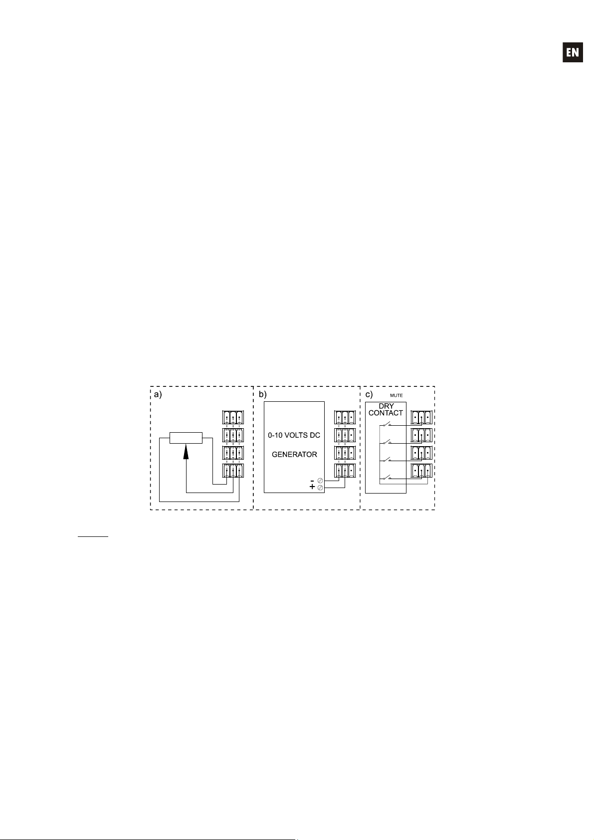
Los símbolos de relámpagos dibujados cerca de los terminales de salida se utilizan para
alertar al usuario del riesgo de descargas peligrosas. Los conectores de salida que
podrían plantear algún riesgo se indican con este símbolo del relámpago. No toque los
terminales de salida mientras que el amplificador esté encendido. Hacer todas las
conexiones con el amplificador apagado.
ADVERTENCIA: para prevenir choques eléctricos o riesgo de incendios, no exponer este equipo a la
lluvia o la humedad.
INSTRUCCIONES IMPORTANTES DE SEGURIDAD
1. Lea estas instrucciones
2. Guarde estas instrucciones
3. Preste atención a todas las advertencias
4. Siga todas las instrucciones
5. No utilice este aparato cerca del agua
6. Límpielo solamente con un paño seco
7. No bloquee ninguna abertura para ventilación. Instálelo de acuerdo con las instrucciones del
fabricante
8. No lo instale cerca de fuentes de calor como radiadores, estufas u otros aparatos que produzcan
calor, incluidos amplificadores.
9. No elimine el propósito de seguridad del cable de corriente polarizado o con conexión de tierra.
Un cable polarizado tiene dos bornes, uno más ancho que el otro. Un enchufe con conexión a
tierra, tiene dos bornes y un tercer borne conectado a tierra. Este tercer borne está previsto para
su seguridad. Si el cable proporcionado no entra en su enchufe, consulte con un técnico
electricista para reemplazar ese enchufe obsoleto.
10. Proteja el cable eléctrico de ser aplastado, en especial en la zona de los conectores, los
receptáculos de los mismos y en el punto en el que el cable sale del aparato.
11. Utilice solamente los accesorios especificados por el fabricante.
12. Desconecte el aparato durante las tormentas eléctricas o cuando no lo vaya a usar durante
periodos largos de tiempo.
13. Para cualquier reparación, póngase en contacto con un servicio técnico cualificado. La
reparación es necesaria cuando el aparato no funciona con normalidad o ha sido dañado por
cualquier motivo, ya sea porque el cable o el enchufe estén dañados, porque se hayan
derramado líquidos o hayan caído objetos dentro del aparato, o porque el aparato haya sido
expuesto a la lluvia o se haya caído.
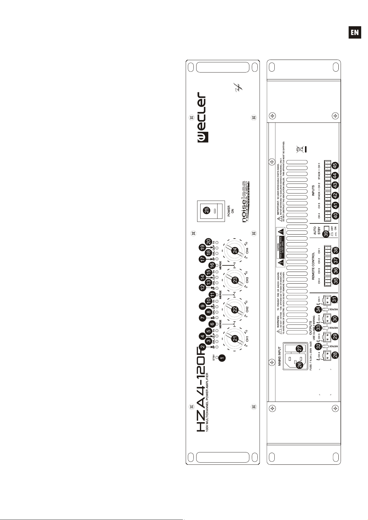
14. Desconexión de la red: apagando el interruptor de POWER (25) todas las funciones e
indicadores del amplificador se pararán, pero la completa desconexión del aparato se consigue
desconectando el cable de red de su conector (26). Por esta razón, éste siempre debe tener fácil
acceso.
15. ¡Precaución! Los radiadores laterales pueden tener bordes cortantes.

11
ÍNDICE
1. NOTA IMPORTANTE 12
2. INTRODUCCIÓN 12
3. INSTALACIÓN 12
3.1. Ubicación y montaje 12
3.2. Conexión a red 13
3.3. Conexiones de entrada de señal 13
3.4. Conexiones de salida y enlace de canales mediante función FLEXIPOWER 14
3.5. Conmutadores internos para filtros paso-altos 14
3.6. Puertos de control remoto de atenuación 14
3.7. Conexionado de los puertos REMOTE CONTROL 15
4. FUNCIONAMIENTO 15
4.1. Puesta en marcha 15
4.2. Indicadores LED del panel frontal 15
4.3. Controles de volumen del panel frontal 16
4.4. Conmutador AUTO STBY ON / OFF 16
5. LIMPIEZA 16
6. DIAGRAMAS 17
6.1. Lista de funciones 17
6.2. Diagrama de funciones 17
6.3.Característicastécnicas 34
6.4. Diagrama de configuración 35
6.5. Diagrama de bloques 35
Todos los datos están sujetos a variación debida a tolerancias de producción. ECLER S.A. se reserva el derecho de
realizar cambios o mejoras en la fabricación o diseño que pudieran afectar las especificaciones.

12
1. NOTA IMPORTANTE
¡Enhorabuena!. Vd. posee el resultado de un cuidadoso diseño y una esmerada fabricación.
Agradecemos su confianza por haber elegido nuestra etapa de potencia multicanal HZA4-120F.
Para conseguir la máxima operatividad del aparato y su máximo rendimiento, es MUY
IMPORTANTE antes de su conexión, leer detenidamente y tener muy presentes las consideraciones que
en este manual se especifican.
Para garantizar el óptimo funcionamiento de este aparato, recomendamos que su mantenimiento
sea llevado a cabo por nuestros Servicios Técnicos autorizados.
2. INTRODUCCIÓN
El HZA4-120F es un amplificador de potencia de cuatro canales con salidas amplificadas
directamente en alta impedancia (línea de 100 V). Sus principales características son:
Estructura interna de 4 amplificadores mono independientes, para 4 señales de entrada mono
diferentes.
Tecnología FLEXIPOWER, que permite enlazar 2, 3 ó 4 canales adyacentes, sumando sus
potencias individuales y funcionando a todos los efectos como un único canal amplificador de
potencia total equivalente a dicha suma.
Ajuste de volumen independiente (por canal), mediante controles en panel frontal
Control de volumen remoto 0 – 10 VDC independiente (por canal), accesible mediante
terminales atornillables en panel posterior.
Tecnología SPM 100 Technology - Channel N de amplificación directa en alta impedancia (línea
de 100 V), sin transformadores de salida, la cual presenta los siguientes valores añadidos frente
a la amplificación clásica para línea de 100 V, mediante transformadores:
oMejor respuesta frecuencial en la banda baja del espectro audible (frecuencias graves),
al no existir la habitual degradación de esta parte del espectro debida a la saturación del
núcleo de los transformadores.
oGran rendimiento.
oReducido peso.
Ventilación por convección, sin ventiladores, que aporta:
oRuido de fondo inexistente.
oFiabilidad incrementada.
Función de “auto stand-by”: el amplificador pasa automáticamente al modo de reposo (consumo
reducido) al no detectar señal en las entradas durante un período aproximado de 2 minutos,
volviendo de manera inmediata al régimen de trabajo normal al detectar de nuevo señal en ellas.
Protección térmica.
Protección por sobrecarga.
Sistema “anticlip” o anti-saturación por exceso de señal.
3. INSTALACIÓN
3.1. Ubicación y montaje
El amplificador se presenta en módulo rack de 19" y dos unidades de altura, se suministra con
arandelas de plástico con el fin de poderlo montar en un rack sin dañar el aparato.
Es muy importante que, como elemento generador de calor que es, el amplificador no esté
completamente encerrado ni expuesto a temperaturas extremas. Debe favorecerse el paso de aire
fresco a través de los orificios de ventilación del chasis, dejando al menos una unidad de rack
libre entre cada equipo y los instalados encima y debajo de él en el bastidor de rack.
Si la instalación consta de varios amplificadores en el mismo rack o se realiza dentro de
armarios cerrados mediante puertas, es altamente recomendable dotar a éstos de ventilación forzada

13
ascendente, instalando ventiladores en sus extremos inferior y superior. Dicho flujo ascendente de
ventilación favorecerá la disipación del calor generado en su interior.
Con el objeto de favorecer en la medida de lo posible la correcta disipación térmica de los
equipos instalados en armarios rack, es aconsejable no colocar los amplificadores de potencia debajo
de otros aparatos, sino encima de éstos.
3.2. Conexión a red
El amplificador se alimenta con corriente alterna, según el país, de 110-120, 220-240V 47-63Hz.
(ver placa de características en el aparato).
La etapa debe conectarse a una toma de tierra en condiciones (Resistencia de tierra, Rg=30o
menos). El ambiente de trabajo deberá ser seco y estar totalmente libre de polvo. No exponga el
aparato a la caída de agua o salpicaduras, no ponga encima objetos con líquido ni fuentes de llama
desnuda, como velas. No obstruya los orificios de ventilación con ningún tipo de material.
En caso de requerir alguna intervención y/o conexión-desconexión del amplificador debe
desconectarse previamente la alimentación. En el interior del amplificador no existen elementos
manipulables por el usuario.
Debe evitarse que el cable de red se entremezcle con los cables blindados que transportan la
señal de audio, ya que ello podría ocasionar la aparición de interferencias y zumbidos.
Para proteger al amplificador de eventuales sobrecargas en la línea de red o bien excesos
ocasionales en el consumo de los circuitos internos, está provisto de un fusible de red. En caso de que
éste se fundiera se desconectaría el aparato y se sustituiría por otro de idénticas características. Si éste
último se volviera a fundir, consulte con nuestro Servicio Técnico.
PRECAUCIÓN: EN NINGÚN CASO DEBE PONERSE UN FUSIBLE DE VALOR MÁS
ELEVADO.
3.3. Conexiones de entrada de señal
El amplificador HZA4-120F dispone en su panel posterior de 4 entradas analógicas de señal,
balanceadas y con nivel de línea (una por canal de amplificación).
Los conectores de entrada de señal son
del tipo de regleta de tornillos de tres contactos
(40, 41, 43, 45). La asignación del conexionado
es la siguiente:
Vivo o señal directa > Terminal +
Frío o señal invertida > Terminal -
Masa > Terminal
Para conexiones NO balanceadas
cortocircuitar a masa el terminal -.
Las salidas STACK (42, 44), disponibles para las entradas 1 y 2, están en paralelo con las
entradas y sirven para conectar la misma señal que tenemos en dichas entradas (INPUTS, CH1 / CH2)
a otros canales de entrada, amplificadores o sistemas de sonido.
La impedancia de entrada es de 20 k(balanceada) con una sensibilidad nominal de 0 dBV
(1V). Esta impedancia permite conectar un gran número de etapas en paralelo sin merma de la calidad
sonora.

14
3.4. Conexiones de salida y enlace de canales mediante función FLEXIPOWER
La sección OUTPUT del panel posterior está provista de una regleta atornillable de dos
contactos (28, 29, 30, 31) para cada uno de los 4 canales del amplificador. Respete siempre la
polaridad relativa de las salidas (marcas 0 y 100V de cada conector de salida), cableado y altavoces.
Funcionamiento de la función FLEXIPOWER: entre cada pareja de conectores de salida se
encuentra un conmutador denominado MERGE:
Cuando dicho conmutador se encuentra en su posición superior, la pareja de canales se
comporta de manera independiente, estando la función FLEXIPOWER desactivada
Cuando el conmutador pasa a la posición inferior (MERGE) los dos canales quedan
enlazados y sus potencias individuales sumadas:
oLas dos salidas de la pareja de canales quedan conectadas en paralelo, así como las
líneas de altavoces que alimentan
oSe ilumina el indicador LED MERGE (6, 11, 16) del panel frontal ubicado entre la
pareja de canales en cuestión
oEl contenido de audio de la pareja de canales pasa a ser el de la fuente sonora
conectada a la entrada del canal de numeración inferior (entrada 1 para pareja 1&2,
entrada 2 para pareja 2&3, entrada 3 para pareja 3&4)
oEl control de volumen frontal y el remoto (si se emplease) efectivo sobre la pareja
pasa a ser el del canal de numeración inferior (controles canal 1 para pareja 1&2,
controles canal 2 para pareja 2&3, controles canal 3 para pareja 3&4)
PRECAUCIÓN: NO MANIPULAR LOS CONMUTADORES “MERGE” CON EL
AMPLIFICADOR EN MARCHA
Es posible enlazar 2, 3 o 4 canales adyacentes (doble, triple o cuádruple potencia resultante), quedando
la disposición de fuentes sonoras y controles de volumen de la siguiente forma:
3.5. Conmutadores internos para filtros paso-altos
En el interior del amplificador existen 4 puentes (“jumpers”) para activar / desactivar la función de
filtro paso-altos de cada canal del amplificador, con frecuencia de corte fijada en 70 Hz y con pendiente
de 18 dB / octava. El filtro paso-altos es aconsejable que actúe en determinadas aplicaciones sobre
línea de 100 V, en especial cuando el contenido sonoro a reproducir es principalmente vocal (avisos de
megafonía, por ejemplo).
Consulte el DIAGRAMA DE CONFIGURACIÓN para más información.
3.6. Puertos de control remoto de atenuación
El HZA4-120F dispone, en su panel posterior, de 4 puertos de control remoto rotulados como
“REMOTE CONTROL” (35, 36, 37, 38). Es posible conectar a cada uno de estos puertos de control un
panel de la serie WPm, REVO, etc. de manera que éste actúe atenuando la señal de entrada (y por lo
tanto, el volumen de salida de los canales afectados) de forma remota.
El nivel máximo de señal de cada canal de amplificación, y por lo tanto su volumen de salida, se
emplee o no en él la atenuación remota, lo determina la posición de su control rotativo frontal (21, 22, 23,
24).
Independent1&22&33&41&2&32&3&41&2&3&4
CHANNEL1IN1IN1IN1IN1
CHANNEL2IN2IN2
CHANNEL3IN3IN3
CHANNEL4IN4IN4IN4 IN4
MERGEDCHANNELS
FLEXIPOWERinputsroutingandassociatedvolumecontrols
IN1
IN2
IN3
IN1
IN2 IN1

15
3.7. Conexionado de los puertos REMOTE CONTROL
El nivel de atenuación remota de la señal para cada uno de los canales de entrada puede ser fijado
mediante el empleo de 3 tipos de dispositivos externos, conectados a los puertos REMOTE CONTROL del
panel posterior:
a) Un potenciómetro, de valor nominal comprendido entre 10 ky 50 k, serie WPm o equivalente
b) Un dispositivo generador de señal de control 0-10 V DC
c) Un relé / contacto seco remoto
NOTA: Puede conectar un máximo de 16 puertos REMOTE CONTROL en paralelo a un mismo
potenciómetro físico de control. Es imprescindible que todas las masas de los amplificadores a
los que pertenecen dichos puertos estén unidas.
Los cables de conexión pueden ser de hasta 500 metros aproximadamente, utilizando una
sección mínima de 0,5 mm2.
Consulte a su distribuidor ECLER o bien en www.ecler.com acerca de los accesorios disponibles
para la conexión a puertos remotos.
4. FUNCIONAMIENTO
4.1. Puesta en marcha
Esta se realizará mediante el interruptor de red POWER ON (25) e inmediatamente se iluminará el
piloto integrado en el propio interruptor.
En una instalación completa de audio es importante poner en marcha el equipo de acuerdo con
la siguiente secuencia: fuentes de sonido, mezclador, ecualizadores, filtros activos, procesadores y
finalmente los amplificadores de potencia. Para pararlos, la secuencia debe seguirse a la inversa.
4.2. Indicadores LED del panel frontal
El HZA4-120F equipa los siguientes indicadores LED en su panel frontal:
Indicador STBY (1): se ilumina cuando el amplificador se halla en el estado de reposo (bajo
consumo), tras haber detectado ausencia de señal en sus entradas durante un período
aproximado de 2 minutos. Al detectar de nuevo señal de entrada, el amplificador regresa
automáticamente al régimen normal de trabajo.
Indicadores de presencia de señal SP (2, 7, 12, 17): advierten de la presencia de señal en las
entradas del amplificador. Estos indicadores se iluminan cuando la señal presente en la entrada
supera los –35 dB.
Indicadores de sobrecarga, OVL (3, 8, 13, 18): se iluminan cuando el canal llega a su límite de
capacidad de entrega de corriente, debido a una carga con impedancia excesivamente baja.
Indicadores CLIP (4, 9, 14, 19): se iluminan cuando la señal entregada a los altavoces se
encuentra cercana al nivel de recorte real. Este sistema de CLIP tiene en cuenta las posibles
fluctuaciones en la tensión de alimentación, dando siempre una indicación real aunque éstas

16
existan. Es normal que trabajando a niveles elevados de potencia los indicadores de CLIP se
iluminen al ritmo de las frecuencias graves, que son las que poseen mayor contenido energético.
Debe procurarse que estos indicadores no queden iluminados de una forma permanente por
esta razón durante el régimen normal de trabajo del equipo.
Indicadores de protección térmica, TH (5, 10, 15, 20): indican que el canal ha entrado en estado
de protección por exceso de temperatura, restableciendo su funcionamiento normal cuando su
temperatura regrese al margen de temperatura de trabajo considerado correcto.
Indicadores MERGE: indican si la función de enlace FLEXIPOWER entre dos canales
adyacentes se encuentra o no activada mediante los conmutadores del panel posterior.
4.3. Controles de volumen del panel frontal
El panel frontal integra 4 controles rotatorios de volumen, uno por canal, que permiten el ajuste
del nivel máximo de salida de cada uno de los canales del amplificador de manera independiente.
Los puertos de control remoto también permiten un ajuste del volumen de cada canal del
amplificador desde un panel serie WPm, un potenciómetro u otro dispositivo físico externo, siendo el
volumen efectivo de cada canal el resultado de la posición de ambos controles de volumen (frontal y
remoto).
En el embalaje del aparato encontrará una bolsa con tapones transparentes insertables sobre
los controles rotativos del panel frontal. Su función es proteger los ajustes de atenuación de entrada
ante manipulaciones no deseadas tras la puesta en marcha de la instalación. Una vez insertados es
necesario utilizar un destornillador plano o herramienta similar para retirarlos.
4.4. Conmutador AUTO STBY ON / OFF
Conmutador (39) que activa / desactiva la función auto “stand-by” (modo de reposo o bajo
consumo). Si se activa dicha función, el amplificador entrará en el estado de reposo tras haber
detectado ausencia de señal en sus entradas durante un período aproximado de 2 minutos. Al detectar
de nuevo señal de entrada, el amplificador regresa automáticamente al régimen normal de trabajo
5. LIMPIEZA
La carátula no deberá limpiarse con sustancias disolventes o abrasivas puesto que se corre el
riesgo de deteriorar la serigrafía. Para su limpieza se utilizará un trapo humedecido con agua y un
detergente líquido neutro, secándola a continuación con un paño limpio. En ningún caso se debe permitir
la entrada de agua por cualquiera de los orificios del aparato.

17
6. DIAGRAMAS
6.1. Lista de funciones 6.2. Diagrama de funciones
1. Indicador de apagado automático, STBY
2. Indicador de presencia de señal, SP CH 1
3. Indicador de carga excesiva, OVL CH 1
4. Indicador de recorte, CLIP CH 1
5. Indicador de protección térmica, TH CH 1
6. Indicador de enlace, MERGE 1 & 2
7. Indicador de presencia de señal, SP CH2
8. Indicador de carga excesiva, OVL CH 2
9. Indicador de recorte, CLIP CH 2
10. Indicador de protección térmica, TH CH 2
11. Indicador de enlace, MERGE 2 & 3
12. Indicador de presencia de señal, SP CH 3
13. Indicador de carga excesiva, OVL CH 3
14. Indicador de recorte, CLIP CH 3
15. Indicador de protección térmica, TH CH 3
16. Indicador de enlace, MERGE 3 & 4
17. Indicador de presencia de señal, SP CH 4
18. Indicador de carga excesiva, OVL CH 4
19. Indicador de recorte, CLIP CH 4
20. Indicador de protección térmica, TH CH 4
21. Volumen, CH 1
22. Volumen, CH 2
23. Volumen, CH 3
24. Volumen, CH 4
25. Interruptor y piloto de puesta en marcha,
POWER
26. Base de red
27. Portafusibles
28. Terminales atornillables salida 4, CH 4
29. Terminales atornillables salida 3, CH 3
30. Terminales atornillables salida 2, CH 2
31. Terminales atornillables salida 1, CH 1
32. Conmutador de enlace, MERGE 3 & 4
33. Conmutador de enlace, MERGE 2 & 3
34. Conmutador de enlace, MERGE 1 & 2
35. Terminales atornillables control remoto, CH 4
36. Terminales atornillables control remoto, CH 3
37. Terminales atornillables control remoto, CH 2
38. Terminales atornillables control remoto, CH 1
39. Selector modo reposo, AUTO STBY
40. Terminales atornillables de entrada 4, CH 4
41. Terminales atornillables de entrada 3, CH 3
42. Terminales atornillables para la conexión en
cadena, STACK CH 2
43. Terminales atornillables de entrada 2, CH 2
44. Terminales atornillables para la conexión en
cadena, STACK CH 1
45. Terminales atornillables de entrada 1, CH 1

18
Explication des symboles graphiques
Le symbole d'éclair avec une flèche, à l'intérieur d'un triangle équilatéral, avertit
l'utilisateur de la présence de « tension dangereuse », non isolée, à l'intérieur de
l'enceinte du produit, assez importante pour constituer un risque d'électrocution des
personnes.
Le point d'exclamation dans un triangle équilatéral avertit l'utilisateur de l'existence
d'importantes instructions d'opération et de maintenance (entretien courant) dans les
documents qui accompagnent l'appareil.
Les éclairs imprimés près des bornes de SORTIE de l'amplificateur avertissent l'utilisateur
du risque d'énergie dangereuse. Les connecteurs de sortie qui pourraient constituer un
risque sont marqués d'un éclair. Ne touchez pas les bornes de sortie lorsque
l'amplificateur est en marche. Réalisez toutes les connexions lorsque l'amplificateur est
éteint.
AVERTISSEMENT : Afin d'éviter tout incendie ou électrocution, n'exposez pas cet appareil à la pluie ou
l'humidité
CONSIGNES DE SÉCURITÉ IMPORTANTES
1. Lisez ces instructions.
2. Conservez ces instructions.
3. Prenez en compte tous les avertissements.
4. Suivez toutes les instructions.
5. N'utilisez pas cet appareil près de l'eau.
6. Nettoyez uniquement à l'aide d'un chiffon sec.
7. Ne bloquez pas les ouvertures d'aération. Installez en respectant les instructions du fabricant.
8. Ne l'installez pas près de sources de chaleur telles que des radiateurs, des bouches d'air chaud,
des cuisinières ou d'autres appareils (amplificateurs inclus) qui produisent de la chaleur.
9. N'entravez pas la sécurité de la fiche polarisée ou de la prise de mise à la terre. Une fiche
polarisée possède deux lames, dont une est plus large que l'autre. Une prise de mise à la terre
possède deux lames, ainsi qu'une broche de masse. La lame large ou la troisième broche sont
fournies pour votre sécurité. Si la fiche fournie ne correspond pas à votre prise de courant,
consultez un électricien pour le remplacement de l'ancienne prise.
10. Protégez le cordon d'alimentation afin qu'il ne soit ni écrasé ni pincé, en particulier au niveau des
fiches, des prises de courant et à l'endroit où ils sortent de l'appareil.
11. N'utilisez que des accessoires recommandés par le fabricant.
12. Débranchez l'appareil en cas d'orage ou s'il n'est pas utilisé pendant une longue période.
13. L'entretien courant doit être réalisé par du personnel qualifié. L'entretien courant doit être réalisé
lorsque l'appareil a été endommagé, par exemple lorsque le cordon d'alimentation ou la fiche
sont endommagés, si du liquide a été renversé ou si des objets sont tombés sur l'appareil, si
l'appareil a été exposé à la pluie ou à l'humidité, s'il ne fonctionne pas normalement ou s'il est
tombé.
14. Déconnexion du secteur: En appuyant sur l'interrupteur POWER (25), toutes les fonctions et les
voyants de l'amplificateur seront mis à l'arrêt, mais la déconnexion totale de l'appareil s'effectue
en débranchant le cordon d'alimentation du secteur (26). C'est la raison pour laquelle il doit
toujours rester opérationnel.
15. Attention ! Les radiateurs latéraux peuvent avoir des arêtes coupantes.

19
TABLE DES MATIERES
1. NOTE IMPORTANTE 20
2. INTRODUCTION 20
3. INSTALLATION 21
3.1. Situation et montage 21
3.2. Branchement 21
3.3. Branchement de l'entrée du signal 21
3.4. Branchement de sortie. et interconnexion de voies au moyen de la
fonction FLEXIPOWER 22
3.5. Commutateurs internes pour filtres passe-haut 23
3.6. Ports de télécommande d'atténuation 23
3.7. Connexion des ports de télécommande REMOTE CONTROL 23
4. MISE EN MARCHE ET UTILISATION. FONCTIONNEMENT 23
4.1. Mise en marche 23
4.2. Témoins LED de la face avant 24
4.3. Réglages de volume de la face avant 24
4.4. Commutateur AUTO STBY ON/OFF 24
5. ENTRETIEN 24
6. SCHÉMAS 25
6.1. Liste de fonctions 25
6.2. Schéma de fonctionnement 25
6.3. Caractéristiques techniques 34
6.4. Schéma de configuration 35
6.5. Diagramme de blocs 35
Toutes les valeurs mentionnées dans ce document sont susceptibles d’être modifiées en raison des tolérances de
production. ECLER SA se réserve le droit de changer ou d’améliorer les processus de fabrication ou la présentation de
ses produits, occasionnant ainsi des modifications dans les spécifications techniques.

20
1. NOTE IMPORTANTE
Félicitations ! Vous avez en votre possession le résultat d’un design et d’une fabrication
particulièrement soignée. Nous vous remercions de la confiance que vous nous portez en choisissant notre
amplificateur HZA4-120F.
Pour obtenir le meilleur résultat de cet appareil, il est important de lire attentivement les instructions
ci-dessous avant de le brancher.
Pour obtenir le meilleur rendement de cet appareil, il est important que l’entretien soit réalisé par
notre Service Technique.
2. INTRODUCTION
Le HZA4-120F est un amplificateur de puissance quatre canaux avec sorties amplifiées
directement en haute impédance (ligne 100 V). Ses principales caractéristiques sont :
Structure interne à quatre amplificateurs mono séparés, pour 4 signaux d'entrée mono différents.
Technologie FLEXIPOWER qui permet de connecter 2, 3 ou 4 voies adjacentes entre elles en
additionnant leur puissance individuelle, le tout fonctionnant comme une seule voie
d'amplification dont la puissance totale est équivalente à cette somme.
Réglage de volume indépendant (par canal) grâce à des commandes en face avant
Commande à distance et indépendante (par canal) du volume par CC 0-10 V, via les borniers à
vis de la face arrière.
Technologie SPM 100 Technology - Channel N d’amplification directe en haute impédance (ligne
100 V) sans transformateurs de sortie, ce qui a les avantages suivants par rapport à
l'amplification classique en ligne 100 V utilisant des transformateurs :
oMeilleure réponse en fréquence dans la bande basse du spectre audible (fréquences
basses ou graves) en l'absence de la dégradation habituelle de cette partie du spectre
par la saturation du noyau des transformateurs.
oHaut rendement.
oPoids réduit.
Refroidissement par convection, sans ventilateur, qui a pour avantages :
oBruit de fond inexistant.
oFiabilité accrue.
Fonction “auto stand-by” : l'amplificateur passe automatiquement en mode veille (basse
consommation) si aucun signal d'entrée n’est détecté durant une période d'environ deux minutes,
puis revient immédiatement en service normal quand un signal est de nouveau détecté.
Protection thermique.
Protection contre les surcharges.
Système “anticlip” (anti-écrêtage) ou anti-saturation par signal excessif.
Table of contents
Languages:
Other Ecler Amplifier manuals

Ecler
Ecler eWAMPBT+ User manual

Ecler
Ecler UMA SB118 User manual

Ecler
Ecler CA40 User manual

Ecler
Ecler eCA120HZDN User manual

Ecler
Ecler HSA300 User manual

Ecler
Ecler MPA6-150R User manual

Ecler
Ecler PAM4100 User manual

Ecler
Ecler eCA120HZ User manual

Ecler
Ecler HSA2-400ES User manual

Ecler
Ecler MPA4-150R User manual

Ecler
Ecler CA120HZ User manual

Ecler
Ecler AMBIT SB110 User manual

Ecler
Ecler PAM1100 User manual

Ecler
Ecler GPA2-400ES User manual

Ecler
Ecler VEO-SPH48 User manual

Ecler
Ecler MPA6-80R User manual

Ecler
Ecler Dante VIDA-24Q User manual

Ecler
Ecler MPA4-400 User manual

Ecler
Ecler MPA280 User manual

Ecler
Ecler LPA6000 User manual