Ecler Ampack2-20 User manual

USER MANUAL
MANUAL DE INSTRUCCIONES
NOTICE D'UTILISATION
BEDIENUNGSANLEITUNG

2

3
INSTRUCTION MANUAL
1. IMPORTANT REMARK 04
1.1. Conformity with international standards 04
2. INTRODUCTION 04
3. INSTALLATION 05
3.1. Placement and mounting 05
3.2. Mains connection 05
3.3. Input connections 06
3.4. Output connections 06
3.5. Input/Output options 07
4. OPERATION AND USAGE
07 4.1. Start up 07
4.2. Input attenuation 07
4.3. Remote control 08
4.4. Connection of the VCA control 08
4.5. AUTO STANDBY function 09
4.6. Indicators 09
4.7. DLAPACK2-70 10
5. CLEANING 10
6. FUNCTION LIST 11
7. FUNCTION DIAGRAM 11
8. TECHNICAL CHARACTERISTICS 39
9. BLOCK DIAGRAM 40

4
All numbers subject to variation due to production tolerances. ECLER SA reserves the right to make changes or
improvements in manufacturing or design which may affect specifications.

5
1. IMPORTANT REMARK
Congratulations! You are the owner of a carefully designed and manufactured equipment.
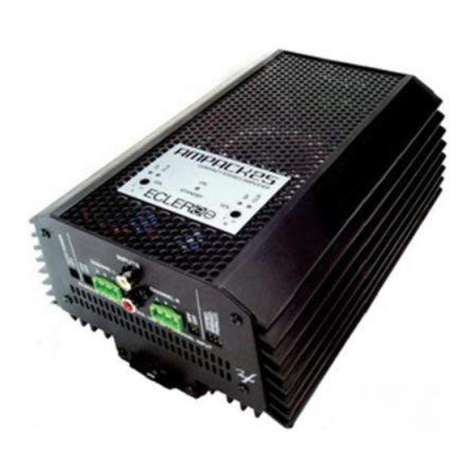
We thank you for having purchased our AMPACK2-70 / 4-70 compact amplifier or DLAPACK2-70 line
adaptor. It is VERY IMPORTANT that you read this manual before connecting the amplifier in order
to obtain its maximum performance.
We recommend our authorised Technical Services whenever any maintenance task
should be needed so that optimum operation shall be achieved.
1.1. Conformity with international standards
The AMPACK2-70 / 4-70 amplifier series complies with the following international standards:
•EN55103-1 Electromagnetic compatibility.
•Product family standard for audio, video, audio-visual and entertainment lightning control
apparatus for professional use
•Part 1: Emission
•EN55103-2 Electromagnetic compatibility.
•Product family standard for audio, video, audio-visual and entertainment lightning control
apparatus for professional use
•Part 2: Immunity
•EN60065 Audio, video and similar electronic apparatus. Safety requirements
Guidelines 73/23/EEC and 2004/108/EC are therefore accomplished
2. INTRODUCTION
The AMPACK2-70 / 4-70 compact amplifier series offers to the installer the most resistant and
reliable amplification technology available on the professional audio market. Its compact and silent
design allows its usage in nearly every place and application that requires power values up to 4 x 70W
RMS at low impedance (4Ω). For 100V line applications, you need to use the DLAPACK2-70 dual
converter to transform two 70W channels at 4 Ωin two 70W channels for 100V line (see paragraph 4.7.
DLAPACK2-70 for more information).

6
Main characteristics:
•2 x 70W RMS (AMPACK2-70) or 4 x 70 WRMS (AMPACK4-70) amplifier at 4 Ω
•Integrated power supply
•AUTO STANDBY: when no signal is present, the AMPACK enters the Standby mode, reducing its
power consumption
•Silent amplifier (convection cooling, without fan)
•Stereo, parallel and bridged operating modes are available
•VCA based remote control for volume (independent for each input channel)
•EUROBLOCK connectors for input, output and VCA remote control
•Additional RCA stereo input jack (AMPACK2-70 only)
•Mono 1+2 switch (AMPACK2-70 only)
•Independent gain controller for each channel, protected against unintentional changes
•Integrated 100Hz high-pass filter
•Direct mounting on 35mm DIN rail
3. INSTALLATION
3.1. Placement and mounting
AMPACK series is suitable for direct mounting on 35mm DIN rail
3.2. Mains connection
The amplifier is powered with alternate current, 220-240V 50/60Hz.
The amplifier should have an earth connection in good conditions (earth resistance, Rg=30Ω
or less). The environment must be dry and dustless. Do not expose the unit to rain or water splashes,
and do not place liquid containers or incandescent objects like candles on top of the unit. Do not
obstruct the ventilation grids with any kind of material.
In case there is some type of intervention and/or connection-disconnection of the
amplifier, it is most important to previously disconnect the mains power supply. There are
no user or serviceable parts inside the amplifier.
You should avoid that the supply cable twists with the shielded signal cables, as this
could lead to unwanted hum.
Additionally, as a corrective measure of hum caused by situations like these ones, the
AMPACK series has a built-in high-pass filter with a 100Hz cut-off frequency and a front panel switch to
activate it.

7
3.3. Input connections
The signal input use electronically balanced EUROBLOCK connectors (7) with input impedance greater
than 20kΩand a nominal sensitivity of 0dBV(1V). The pin out is as follows:
Additionally, the AMPACK2-70 has an unbalanced stereo RCA input (6) for direct
connection of audio sources like CD players, DVD players, media players, etc.
3.4. Output connections
The outputs (11) are located on the front panel with Euroblock connectors.
The cables that connect the AMPACK’s outputs with the loudspeakers must offer high
quality, with sufficient section and as short as possible. This is especially important when the
distance between amplifier and speakers are great; a section of at least 2.5mm
2
is recommended
for distances up to 10m; for greater distances, section should be greater than 4mm
2
.
Remember that the minimum operation impedance is 4Ωwhen using the amplifier
in mono or stereo and 8Ωwhen using the bridge mode. For a correct operation of the AMPACK lower
impedances than the ones described previously should not be used.
Caution: In bridged mode only the terminal indicated on the unit should be used.

8
3.5. Input/Output options
The AMPACK2-70 allows the following operating modes:
•Stereo: channels 1 and 2 are separately amplified and respectively sent to outputs 1 and 2 (the
Mono/Stereo switch, labelled as MONO 1 +2 on the front panel, must NOT be engaged)
•Parallel (Mono): the Mono/Stereo switch, labelled as MONO 1+2 on the front panel, must be
engaged. Channels 1 and 2 are summed and sent to the amplifier channels 1 and 2, each
channel having an independent output volume
•Bridged: the switch should also be engaged, as in the previous case. Observe the output wiring
guidelines indicated on the device when it operates in bridged mode. Channels used in bridged
mode should have their "VOL" attenuators set at the same position, preferably at maximum
level.
The AMPACK4-70 allows the following operating modes:
•Independent: channels 1, 2, 3 and 4 are independently amplified and respectively sent to
outputs 1, 2, 3 and 4
•Parallel: to operate in this mode, you must connect the same input signal to multiple channels
of amplification, each channel having an independent output volume
•Bridged: this mode can operate with channel pairs 1-2 and/or 3-4. This requires connecting the
same input signal to channels 1-2 (and/or 3-4) and wiring outputs as indicated on the
equipment for operating in bridged mode. Channels used in bridged mode should have their
"VOL" attenuators set at the same position, preferably at maximum level.
4. OPERATION AND USAGE
4.1. Start up
This can be done using the power switch (1) and immediately the ON led (3) will start
lightning. We highly recommend the "safe power up sequence": First the sound sources, then mixer,
equalizers, active filters, processors and, finally, power amplifiers. Powering off should be done by
following the exact reverse sequence in order to avoid any possible peaks reaching the next device,
and consequently protecting the loudspeakers, which are specially sensitive to these peaks.
4.2. Input attenuation
These are rotary potentiometers, one per channel, located on the front panel (9) and labelled
as VOL. These attenuators allow connection of different sound source types, independent level
control per channel of amplification and connection of speakers handling less power than the
amplifier can provide at full capacity (avoiding damage by negligence when setting the sound source
volume). An independent level adjustment can be done using a screwdriver or another appropriate
tool.
9
4.3. Remote control
AMPACK provides VCA remote control terminal strips for the volume of each channel,
labelled as REMOTE CONTROL on its front panel.
The combined usage of the rotary potentiometers located at the front panel (9) and the
remote VCA (12) control determines the final value of the signal’s attenuation for each input
channel. Therefore, a certain value can be fixed for the signal attenuation using the rotary so that
the remote control via VCA will not exceed this value and viceversa, that is, the two controls are
connected in series.
4.4. Connection of the VCA control
The signal remote attenuation level for each input channel can be set using 3 types of
external devices connected to REMOTE CONTROL ports on the front panel:
a) Using a remote potentiometer with nominal resistance between 10kΩand 50kΩ.
b) Using a device that generates a control voltage from 0 to 10V DC.
c) Using remote relays/dry contacts.
NOTE: you can connect a maximum of 16 REMOTE CONTROL ports in parallel to the
same hardware control potentiometer. It is essential to assemble all grounds from
amplifiers these ports belong to.
Cables can be up to approximately 500 meters, using a minimum section of 0.5 mm
2
.
Consult the available accessories at your ECLER dealer or at www.ecler.com.

10
4.5. AUTO STANDBY function
The AUTO STANDBY functionality allows flexible installation of the AMPACK series in less
accessible places, since you can leave the device indefinitely connected to mains supply, its activation
or deactivation automatically depending on the presence of an input signal.
If the signal present at any of the device inputs remains under -35dBV for more than 2
minutes, the AMPACK automatically enters in STANDBY mode. This is well indicated by the front panel
ON indicator turning from green (ON) to red (STANDBY).
When in STANDBY mode, the power consumption of the AMPACK2-70 and the
AMPACK4-70 is lower than 9W.
When the signal level becomes higher than -35dBV the device will automatically switch to ON
mode.
4.6. Indicators
The "SP" LED (8) indicates signal presence at the amplifier input. It lights up when the
input level exceeds the set detection threshold.
The "CLlP" LED (10) lights up when the signal delivered to the speakers is nearly really to
clipping or amplifier saturation. This system considers possible variations of the mains voltage,
always giving a real indication independent of the mains voltage. Care should be taken when
adjusting input levels. The CLIP indicators (saturation or clipping) should never stay permanently lit,
but only (and at the most) at the rhythm of the sound sequence lowest frequencies. Otherwise the
signal feeding the power stages would suffer high distortion levels and have low acoustic quality and
intelligibility.

11
4.7. DLAPACK2-70
The DLAPACK2-70 is a dual line adapter converting two low impedance (4 ohms)
amplified signals in two signals suitable to work at high impedance (70 or 100V line). In this way, it is
possible to use an AMPACK2-70 or AMPACK4-70 to connect a high impedance speaker system
(you have to use two DLAPACK units with the AMPACK4-70 and one unit with the AMPACK2-70).
The connection must be made as follows:
1. With all equipment disconnected from mains, connect one at a time the outputs
of the AMPACK2-70 or 4-70 to the inputs of the DLAPACK.
2. Then connect the DLAPACK outputs to the high impedance speaker system,
using for them the 0V (or negative) and 70 or 100V (positive) terminals
depending on whether this system’s speakers are equipped with 70 or 100V
transformers.
In both types of connections always respect signals and wiring polarity.
NOTE: in this type of installation, it is recommended to activate the 100Hz high-pass filter.
5. CLEANING
The AMPACK should not be cleaned with dissolvent or abrasive substances because
silk-printing could be damaged. To clean it, use a soft cloth slightly wet with water and neutral liquid
soap; dry it with a clean cloth. Be careful that water never gets into the amplifier through the holes of the
front panel.

12
6. FUNCTION LIST
1. Power on switch, 0/I
2. Automatic power off configuration, AUTO STANDBY
3. LED indicator, AUTO STANDBY
4. High-pass filter switch, HPF
5. Mono-stereo switch, 1+2
6. Signal input RCA connector, 1 2
7. Input Screwable terminal strip
8. Signal present indicator, SP
9. Channel volume control, VOL
10. Clip indicator, CLIP
11. Output terminals
12. Screwable terminal for remote control
13. Mains socket
14. Input Screwable terminal, INPUTS
15. Line output Screwable terminal, OUTPUTS
7. FUNCTION DIAGRAM

13
MANUAL DE INSTRUCCIONES
1. NOTA IMPORTANTE 13
1.1. Conformidad con normativas internacionales 13
2. INTRODUCCIÓN 13
3. INSTALACIÓN 14
3.1. Ubicación y montaje 14
3.2. Conexión a red eléctrica 14
3.3. Conexiones de entrada 15
3.4. Conexiones de salida 15
3.5. Opciones de entrada / salida 16
4. OPERACIÓN Y USO 16
4.1. Puesta en funcionamiento 16
4.2. Atenuadores de entrada 16
4.3. Control remoto de atenuación VCA 17
4.4. Conexionado del control VCA 17
4.5. Funcionalidad AUTO STANDBY 18
4.6. Indicadores 18
4.7. DLAPACK2-70 19
5. LIMPIEZA 19
6. LISTA DE FUNCIONES 20
7. DIAGRAMA DE FUNCIONES 20
8. CARACTERÍSTICAS TÉCNICAS 39
9. DIAGRAMA DE BLOQUES
40

14
Todos los datos están sujetos a variación debida a tolerancias de producción. ECLER S.A. se reserva el derecho de
realizar cambios o mejoras en la fabricación o diseño que pudieran afectar las especificaciones.

15
1. NOTA IMPORTANTE
¡Enhorabuena!. Vd. posee el resultado de un cuidadoso diseño y una esmerada fabricación.
Agradecemos su confianza por haber elegido nuestro amplificador compacto AMPACK2-70 / 4-70 o
adaptador de línea DLAPACK2-70.
Para conseguir la máxima operatividad del aparato y su máximo rendimiento es MUY
IMPORTANTE, antes de su conexión, leer detenidamente y tener muy presentes las consideraciones
que en este manual se especifican.
Para garantizar el óptimo funcionamiento de este aparato, recomendamos que su
mantenimiento sea llevado a cabo por nuestros Servicios Técnicos autorizados.
1.1. Conformidad con normativas internacionales
La línea de amplificadores AMPACK2-70 / 4-70 es conforme a las siguientes normativas
internacionales:
•EN55103-1 Compatibilidad Electromagnética.
•Norma de familia de Productos para aparatos de uso profesional de sonido, vídeo, sistemas
audiovisuales y para el control de iluminación para espectáculos
•Parte 1: Emisión
•EN55103-2 Compatibilidad Electromagnética.
•Norma de familia de Productos para aparatos de uso profesional de sonido, vídeo, sistemas
audiovisuales y para el control de iluminación para espectáculos
•Parte 1: Inmunidad
•EN60065 Aparatos de audio, vídeo y aparatos análogos. Requisitos de seguridad
Cumpliendo los requisitos de las directrices 73/23/CEE y 2004/108/CE
2. INTRODUCCIÓN
La gama de amplificadores compactos AMPACK2-70 / 4-70 ofrece al instalador la tecnología en
amplificación más robusta y fiable del mercado del audio profesional en un formato compacto,
silencioso y que permite su uso en prácticamente cualquier entorno y aplicación en que se requiera
potencias de hasta 4 x 70 W RMS en baja impedancia (4 Ω). Para aplicaciones sobre línea de 100 V
es preciso emplear el conversor dual DLAPACK2-70, el cual transforma dos canales de 70 W sobre
4 Ωen dos canales de 70 W sobre línea de 100 V (vea el apartado 4.7. DLAPACK2-70 para más
información).

16
Características principales:
•Amplificador de 2 x 70 W RMS (AMPACK2-70) ó 4 x 70 W RMS (AMPACK4-70) sobre 4 Ω
•Fuente de alimentación incorporada
•AUTO STANDBY: en caso de ausencia de señal la unidad AMPACK entra en modo reposo o
Standby, quedando su consumo minimizado
•Amplificador silencioso (ventilación por convección, sin ventilador)
•Admite funcionamiento estéreo, paralelo y puente
•Control remoto de volumen VCA independiente (para cada canal de entrada)
•Conectores EUROBLOCK de entrada, salida y control remoto VCA
•Conector adicional de entrada estéreo RCA (sólo en AMPACK2-70)
•Conmutador mono 1+2 (sólo en AMPACK2-70)
•Ajustes independientes de ganancia para cada entrada, protegidos contra manipulación
accidental
•Filtro pasa altos 100 Hz incorporado
•Directamente instalable en carril DIN 35 mm
3. INSTALACIÓN
3.1. Ubicación y montaje
La línea AMPACK admite la instalación directa en carril DIN 35 mm
3.2. Conexión a red eléctrica
El amplificador se alimenta con corriente alterna, 220-240V 50-60Hz.
El amplificador debe conectarse a una toma de tierra en condiciones (resistencia de tierra,
Rg = 30 Ω, o menor). El ambiente de trabajo deberá ser seco y estar totalmente libre de polvo. No
exponga el aparato a la caída de agua o salpicaduras. No ponga encima objetos con líquido ni
fuentes de llama desnuda, como velas. No obstruya los orificios de ventilación con ningún tipo de
material. En caso de requerir alguna intervención y/o conexión-desconexión del amplificador debe
desconectarse previamente la alimentación. En el interior del amplificador no existen
elementos manipulables por el usuario.
Debe evitarse que el cable de red se entremezcle con los cables blindados que
transportan la señal de audio, ya que ello podría ocasionar zumbidos.
Adicionalmente, y como medida correctora para zumbidos ocasionados por situaciones
como la indicada, la línea AMPACK dispone de un filtro pasa altos incorporado con frecuencia de corte
fija de 100 Hz y activación mediante pulsador en panel frontal.

17
3.3. Conexiones de entrada
Las entradas de señal (7) son del tipo EUROBLOCK balanceadas electrónicamente, con
una impedancia de entrada superior a 20 kΩy una sensibilidad nominal de 0 dBV (1V). La
asignación es la siguiente:
Adicionalmente, el AMPACK2-70 dispone de una entrada (6) RCA estéreo no balanceada
para el conexionado directo de fuentes de audio como CD, DVDs, reproductores multimedia, etc.
3.4. Conexiones de salida
Las salidas (11) se hallan ubicadas en el panel frontal y están provistas de conectores
Euroblock.
El cable de conexión que une las salidas del AMPACK y los altavoces deberá ser de buena
calidad, de suficiente sección y lo más corto posible. Esto tiene especial importancia cuando las
distancias a cubrir son grandes; hasta 10 metros se recomienda una sección no inferior a 2,5 mm
2
y
para distancias superiores, no inferior a 4 mm
2
.
Recuerde que la impedancia mínima de trabajo para los amplificadores en mono o estéreo
es de 4 Ω, y trabajando en modo puente será de 8 Ω. Para un buen funcionamiento del AMPACK bajo
ningún motivo se ha de trabajar con impedancias menores a las especificadas anteriormente.
Atención: en modo puente sólo debe utilizar los terminales indicados en la serigrafía del equipo.

18
3.5. Opciones de entrada / salida
El AMPACK2-70 permite los siguientes modos de trabajo:
•Estéreo: los canales 1 y 2 son amplificados de manera independiente, y enviados a las salidas
1 y 2 respectivamente (el conmutador mono / estéreo, rotulado como MONO 1+2 en el panel
frontal, deberá estar NO pulsado)
•Paralelo (mono): el conmutador mono / estéreo, rotulado como MONO 1+2 en el panel frontal,
deberá estar pulsado. Los canales 1 y 2 son sumados y enviados a los canales de
amplificación 1 y 2, siendo cada canal independiente a efectos del volumen de salida
•Puente: el conmutador también deberá estar pulsado, como en el caso anterior. Respete las
indicaciones para el cableado de salida indicadas en la serigrafía del aparato cuando éste
opere en modo puente. Los atenuadores "VOL" de los canales que se utilizan para hacer el
modo puente se deben colocar en la misma posición, preferiblemente al máximo.
El AMPACK4-70 permite los siguientes modos de trabajo:
•Independiente: los canales 1, 2, 3 y 4 son amplificados de manera independiente, y enviados a
las salidas 1, 2, 3 y 4 respectivamente
•Paralelo: es preciso conectar la misma señal de entrada a varios canales de amplificación
para trabajar en este modo, siendo cada canal independiente a efectos del volumen de salida
•Puente: es posible trabajar en este modo con las parejas de canales 1-2 y/o 3-4. Para ello es
preciso conectar la misma señal de entrada a los canales 1-2 (y/ó 3-4) y realizar el
conexionado de las salidas siguiendo las indicaciones en la serigrafía del equipo para la
operación en modo puente. Los atenuadores "VOL" de los canales que se utilizan para hacer
el modo puente se deben colocar en la misma posición, preferiblemente al máximo.
4. OPERACIÓN Y USO
4.1. Puesta en funcionamiento
Ésta se realizará mediante el interruptor de red (1) e inmediatamente se iluminará el
indicador LED “ON” (3) del panel frontal. Es muy recomendable poner en marcha todos los aparatos
siguiendo la secuencia siguiente: fuentes de sonido, unidad de mezclas, ecualizadores, filtros
activos y procesadores y, finalmente, amplificadores de potencia. El apagado de los aparatos debe
realizarse en la secuencia inversa. Siguiendo este orden los transitorios producidos por el
encendido o apagado de los aparatos no afectarán a los siguientes en la cadena, permaneciendo
inaudibles.
4.2. Atenuadores de entrada
Se trata de potenciómetros rotativos, uno por canal, situados en el panel frontal de la unidad
(9) y rotulados como VOL.
Estos atenuadores posibilitan la conexión de distintos tipos de fuentes de sonido,
regulación de nivel independiente por canal de amplificación y conexión de altavoces que soporten
una potencia inferior a la suministrada por el amplificador a pleno rendimiento (evitando dañarlos
por un descuido al manejar el volumen de la fuente sonora).
Para realizar el ajuste de nivel independiente emplee un destornillador de ajuste u otra
herramienta adecuada.

19
4.3. Control remoto de atenuación VCA
AMPACK dispone, en su panel frontal, de regletas de control remoto VCA del volumen de
cada canal, rotulados como REMOTE CONTROL.
El uso combinado de los potenciómetros rotativos situados en el panel frontal (9) junto con el
control remoto VCA (12) determina el valor final de la atenuación de la señal para cada canal de
entrada. Por tanto, un valor predeterminado de nivel de señal de entrada puede ser fijado mediante los
potenciómetros rotativos, de manera que el control remoto vía VCA no sobrepasará dicho valor, y
viceversa (ambos controles se encuentran en serie).
4.4. Conexionado del control VCA
El nivel de atenuación remota de la señal para cada uno de los canales de entrada puede
ser fijado mediante el empleo de 3 tipos de dispositivos externos, conectados a los puertos REMOTE
CONTROL del panel frontal:
a) Un potenciómetro, de valor nominal comprendido entre 10 kΩy 50 kΩ
b) Un dispositivo generador de señal de control 0-10 V DC
c) Un relé / contacto seco remoto
NOTA: Puede conectar un máximo de 16 puertos REMOTE CONTROL en paralelo a un
mismo potenciómetro físico de control. Es imprescindible que todas las masas de los
amplificadores a los que pertenecen dichos puertos estén unidas.
Los cables de conexión pueden ser de hasta 500 metros aproximadamente, utilizando
una sección mínima de 0,5 mm
2
.
Consulte a su distribuidor ECLER o bien en www.ecler.com acerca de los accesorios
disponibles.

20
4.5. Funcionalidad AUTO STANDBY
La funcionalidad AUTO STANDBY permite flexibilizar la instalación de la línea AMPACK en
lugares poco accesibles, dado que permite dejar el aparato conectado a la red eléctrica de forma
indefinida, activándose o desactivándose éste de forma automática según haya presencia de señal de
entrada o no.
En caso de que la señal presente en cualquiera de las entradas del aparato sea inferior a
-35 dBV durante más de 2 minutos, el AMPACK pasará automáticamente a modo STANDBY
quedando así reflejado mediante el piloto ON ubicado en el panel frontal del dispositivo que pasa de
color verde (ON) a rojo (STANDBY).
En modo STANDBY el consumo del AMPACK2-70 / 4-70 es en ambos casos inferior a 9W.
En el momento que se restaure la señal de entrada por encima de los -30 dBV, el dispositivo
pasara automáticamente a modo ON.
4.6. Indicadores
El indicador LED de presencia de señal “SP” (8), advierte de la presencia de señal en la
entrada del amplificador. Se enciende cuando el nivel en la entrada supera el umbral de detección
establecido.
El indicador LED “CLlP” (10), se ilumina cuando la señal entregada a los altavoces se
halla cercana al nivel de recorte o saturación del amplificador. Este sistema tiene en cuenta las
posibles variaciones en la tensión alterna de alimentación, dando siempre una indicación real e
independiente del nivel de tensión de la red eléctrica. Deben ajustarse los niveles de señal entrante
de manera que nunca queden permanentemente encendidos los indicadores CLIP (saturación o
recorte), sino que lo hagan como máximo al ritmo de las frecuencias más graves del pasaje sonoro.
De lo contrario la señal entregada a las etapas de potencia presentaría altos niveles de distorsión y
una baja calidad acústica e inteligibilidad.
This manual suits for next models
3
Table of contents
Languages:
Other Ecler Amplifier manuals

Ecler
Ecler DLA600B User manual

Ecler
Ecler SAM612T User manual

Ecler
Ecler eCA120 User manual

Ecler
Ecler CA200z User manual

Ecler
Ecler HSA2-400ES User manual

Ecler
Ecler MPA280 User manual

Ecler
Ecler eMOTUS5P User manual

Ecler
Ecler MPA4-150R User manual

Ecler
Ecler NZA4-70 User manual

Ecler
Ecler MPA6-150R User manual

Ecler
Ecler AMPACK Series User manual

Ecler
Ecler eCA120HZ User manual

Ecler
Ecler HSA300 User manual

Ecler
Ecler eHSA SERIES User manual

Ecler
Ecler UMAi SERIES User manual

Ecler
Ecler eCA120HZDN User manual

Ecler
Ecler PKUB User manual

Ecler
Ecler DT4800 User manual

Ecler
Ecler MPA4-400R User manual

Ecler
Ecler DPA2000 User manual