Ecliptech Shift-I Datasheet

1
Installation &
Quick Start Guide
V1.5
This guide will help you install and configure your Shift-I™. It covers connecting the 3
wires, as well as how to configure the unit to suit your vehicle. The User Manual”
(other booklet) provides the specific details on all the features and how to configure
them. First, a brief background as to why these are becoming so popular.
Using an RPM Display…
Tacho gauges mostly go unused, because they are not visible for when you need them.
However to get the most from your engine, they are the most important as they provide
the accurate reference gauge for where the engine makes the most torque. Having a
gauge in your peripheral vision that shows this range of torque, provides a consistent
and focused reference. Up shifting, down shifting, identifying optimal corner entry/exit
gear selection, staging RPM etc… It also provides a reference for performance, to
maintain pace, tyre/fuel management and also to provide immediate feedback on
corner exit RPM vs line taken. It provides a tool to form new habits and break some old
ones, like over braking and coasting. This can increase your level of performance,
control and also engine life. Importantly, this is achieved without taking your eyes off
the road!
Shift-I™
Shift-I™ is a highly engineered progressive RPM indicator. The lights are user
programmable, to allow you to focus on the RPM range you need. You can set where
the first light turns on and where they flash. Usually this is from where the torque kicks
in through to redline. The lights in-between are automatically set at equally spaced
RPM points, which give you a predictable scale for anticipating a smooth & planned
gear change. Various display modes are included to suit your driving requirements.
Why seven lights? Extensive testing determined that within your peripheral vision you
can instantly and easily recognize how many of the seven lights are illuminated. Any
more and you need to concentrate, which would otherwise remove your attention from
where it needs to be. Any less and the RPM trend information is lost. During
acceleration, you will be able to distinguish the progression of the lights. The result is a
consistent reference point with smooth, anticipated shift points.
INSTALLATION WIRING
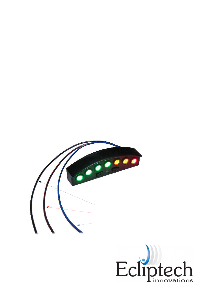
Shift-I requires only three wires to be connected, Ground, Ignition and
Ground = Black
Ignition = Black / Red
Tacho = Black / Blue
Depending on your vehicle, the lists below indicate the common
connection points.
Ground
Ignition
•Frame earth point, drivers side.
•Wiring to instrument cluster.
•ECU Connector.
•
Ignition barrel wiring harness.
•
Wiring to instrument cluster.
•ECU Connector.
•Drivers side fuse panel.
•Radio wiring.
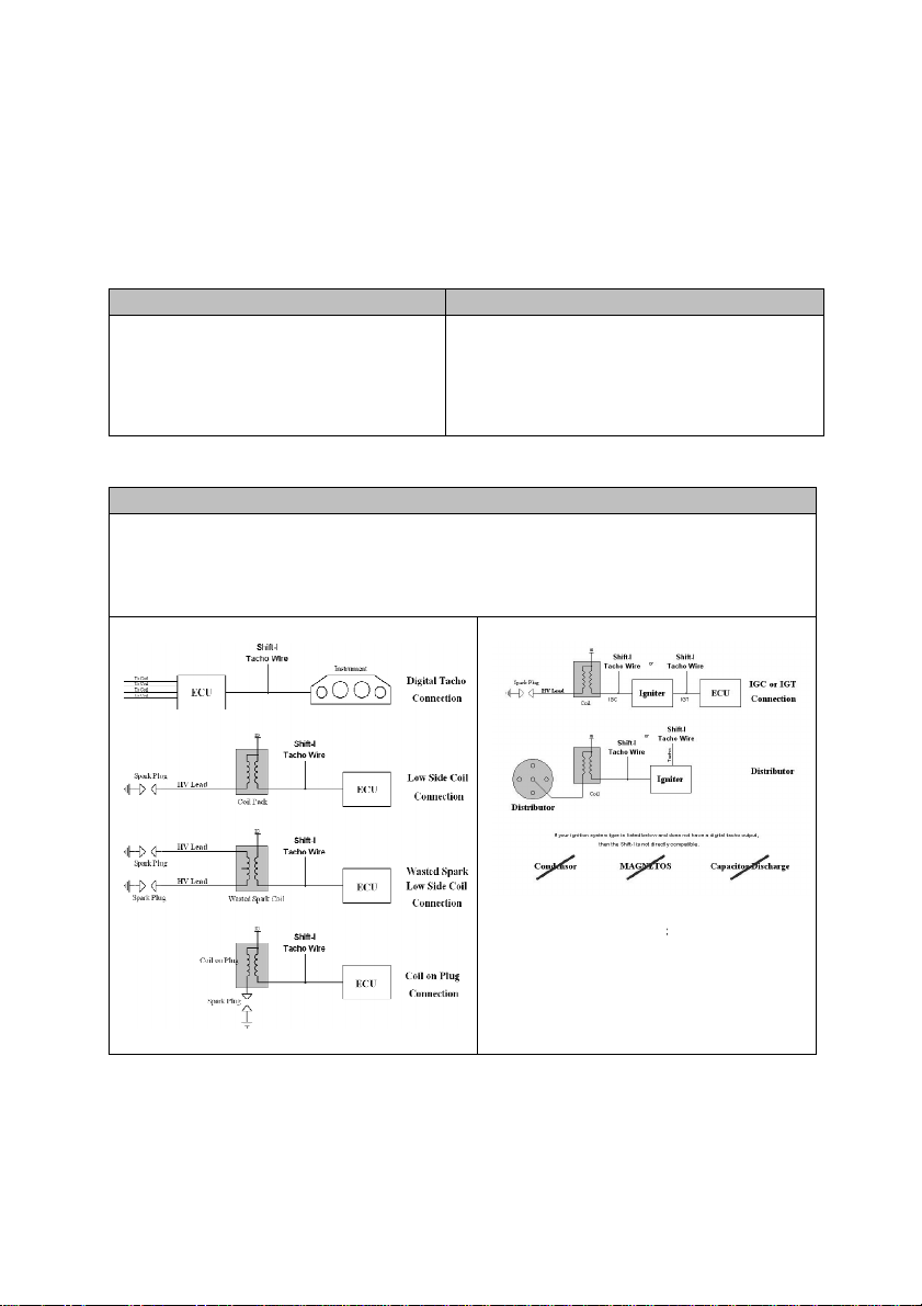
Tacho Signal
•Wiring to instrument cluster.
•Ignition output from ECU (wire going from ECU to coil).
•Connected to the low side of the coil pack, or coil-on-plug.
•Diagnostics connector.
Compatibi
lity with mechanical contact distributors
cannot be guaranteed, as some have excessive
electrical switch contact noise.
Disclaimer: This wiring advice is a guide only and is only to be used
at your own risk
Shift-I is very robust and it will not
be damaged by connecting the wires incorrectly.
accurate way to wire anything is to use the vehicles wiring diagram, however when not available
the information in this guide may be useful.
It is recommended to use a multimeter to verify the
signals before making a connection.
2
Tacho Signal.
connection points.
Ignition barrel wiring harness.
Wiring to instrument cluster.
lity with mechanical contact distributors
cannot be guaranteed, as some have excessive
electrical switch contact noise.
at your own risk
. The
be damaged by connecting the wires incorrectly.
The most
accurate way to wire anything is to use the vehicles wiring diagram, however when not available
It is recommended to use a multimeter to verify the

3
Installation Wiring Guide - Cars
You are welcome to ask Ecliptech if we have any details for fitting your car. Please
advise model/year when enquiring. Alternatively, www.modifiedlife.com and
www.the12volt.com are excellent free sources for wiring information. Our database
grows from customer installation feedback. Any pictures or wiring info you can provide
are kept as reference for other drivers with the model car.
Ground
For vehicles, the easiest place to connect ground is at a local chassis ground point,
around the instrument and pedal area. Take the panel off above the pedals, which is
where you usually find the fuse panel. Look around this area and there is often a bolt
on the chassis frame with one or more wires bolted to it. Connect the Shift-I’s ground
to one of these wires.
If you are connecting the ignition and tacho wires at the instruments wiring harness,
usually it is convenient to wire the ground to the same harness.
Never connect the ground wire near the ignition coils.
Ignition
This wire needs to be connected to a circuit that provides 12 volt power when the
ignition is switched on. Do not use accessories, as this power usually switches off
while cranking. Never connect the power near the ignition coils.
If you are connecting the tacho at the instruments wiring harness, usually it is
convenient to wire the ignition there also.
Alternatively, the key barrel, fuse panel and radio wiring is the easiest to locate. You
can use a multimeter to find a suitable wire, or look for information on the previous two
websites mentioned for more specific information.
Tacho
If you do not have a tacho gauge or it is cable driven, then you will need to connect the
tacho to the ECU/Igniter’s output, or at the coil.
Many of the late 90’s through to ~2005 models have a dedicated tacho signal going
from the ECU to the instrument.
With some vehicles, such as earlier model Porsches, the tacho signal is also available
at the diagnostic connector (as well as ground and ignition).

4
If you have a modern vehicle that uses CAN bus to the instrument, then connect to an
ignition output at the ECU or at a coil-on-plug. To find this wire, look at the coil-on-
plugs (the connector on top of the spark plugs). They have two wires going to them,
one is an ignition output (the wire we want) and the other is power. The power wire for
all the coil-on-plugs are usually the same colour, so you know which one not to use.
To route a wire going to a coil-on-plug, find a grommet going through the firewall near
the pedals and poke a wire through to the engine bay. If you need wire, ask Ecliptech
when ordering. Alternative if you find the same coil-on-plug wire colours at the ECU,
connect there. Depending on the vehicle, sometimes this is more convenient to
access. If you have difficulty, you can always have an auto electrician connect this wire
for you.
www modifiedlife com and www the12volt com are great sources of information for
vehicle wiring.
Installation Wiring Guide - Motorbikes
Often for motorbikes the installation involves connecting all 3 wires to the wire harness
going to the instrument. For some motorbikes, the tacho wire needs to go to the ECU
or the coil.
Ask Ecliptech for wiring info for your model/year bike!
We have a good database already, and may be able to tell you the specific wire colours
you need to connect to.
Motorbike manufacturers do keep some level of consistency with their wiring colours.
The table below shows the typical” wiring colours we see used by the manufacturers
for connecting all 3 wires to the back of the instrument. It is best to contact us, as we
may be able to confirm the wire colours you need.
Manufacturer Ground Ignition Tacho
Ducati ................
Black ................... Violet or Light Blue ....................... Green/Yellow or Green/Grey
Honda ...............
Green .................. Black/Brown or White/Green ....... Yellow/Green
Kawasaki ..........
Black/Yellow ....... Brown/White ................................. Light Blue
Suzuki ...............
Black/White ........ Orange/Green or Red/Yellow ...... Yel/Blue, Yel/Black or Black/Blue
Triumph
............... Black ................... Green/Red ................................... Red
Yamaha ............
Black ................... Light Brown or Red/Yellow .......... Yellow/Black

5
VERIFYING OPERATION
Step 1 – Verify power is connected
The lights should light up successively as soon as ignition is turned on, then shortly
after you will typically see 3 or 4 lights. These 3 or 4 lights are the battery voltage
display, which shows prior to engine start.
Troubleshooting
1. Make sure you have plugged all connectors back together after wiring.
2. Does everything else work… if not, you may have accidentally shorted some wires
during installation. Check all fuses. Don’t forget there may be a separate main
fuse located near the battery.
4. Check the ignition and ground wire to make sure you got the right ones. With
ignition on, measure the voltage at the Shift-I™ to ensure power is there.
Step 2 – Verify Tacho is Connected
IMPORTANT: If you have connected to an ignition output at the ECU/Igniter or to a coil,
then it is recommended to change the “Sensitivity Setting” now. These types of
connections are often electrically very noisy, and can cause display flicker. They can
also make it impossible to get the calibration correct, as the noise can be RPM
dependant. Go to page 17 of the User Manual and reduce the Sensitivity Setting from
the default of 6, down to 4.
When you first turn on ignition, it will show battery voltage. As the Shift-I™ is not yet
calibrated to the vehicle, press either button to exit this mode before starting the
engine”. Start the engine. In the majority of installations, the first light will come on at
either 500, 1000, 2000 or 4000 RPM. The second light would then come on at twice
this value.
If the display is not responding to the engines RPM, first reset the Shift-I to default
settings by holding down both buttons, turn ignition on and keep holding. After about 5
seconds, the display will flash rapidly indicating a successful reset. Release buttons,
start the engine and see if the display now responds to the engine RPM.
Make sure the tacho wire is properly connected to the correct wire on the vehicle. Do
not confuse a Black/Red wire (black with red stripe) with a Red/Black wire (red with
black stripe).
If necessary, try decreasing the Calibration Value” to 0.5 (refer to page 4 of the user
manual).
6
CONFIGURING THE SHIFT-I™
Two settings need be set, Calibration Value and RPM Set-Points.
Calibration Value
The calibration value is a setting that tells the Shift-I™ how many pulses it receives for
each revolution of the engine. This depends on your vehicle and how the tacho signal
is connected. Once this is set correctly, you will have the lights coming on at 1000,
2000, 3000 etc… After the Calibration is set, then this display range can be changed to
suit your preference (next section).
Using the correct Calibration setting is VERY important, as many of the functions,
Inclu ing setting the isplay range, are epen ent on the RPM value.
Most functions are locke out if the RPM is above 2,200.
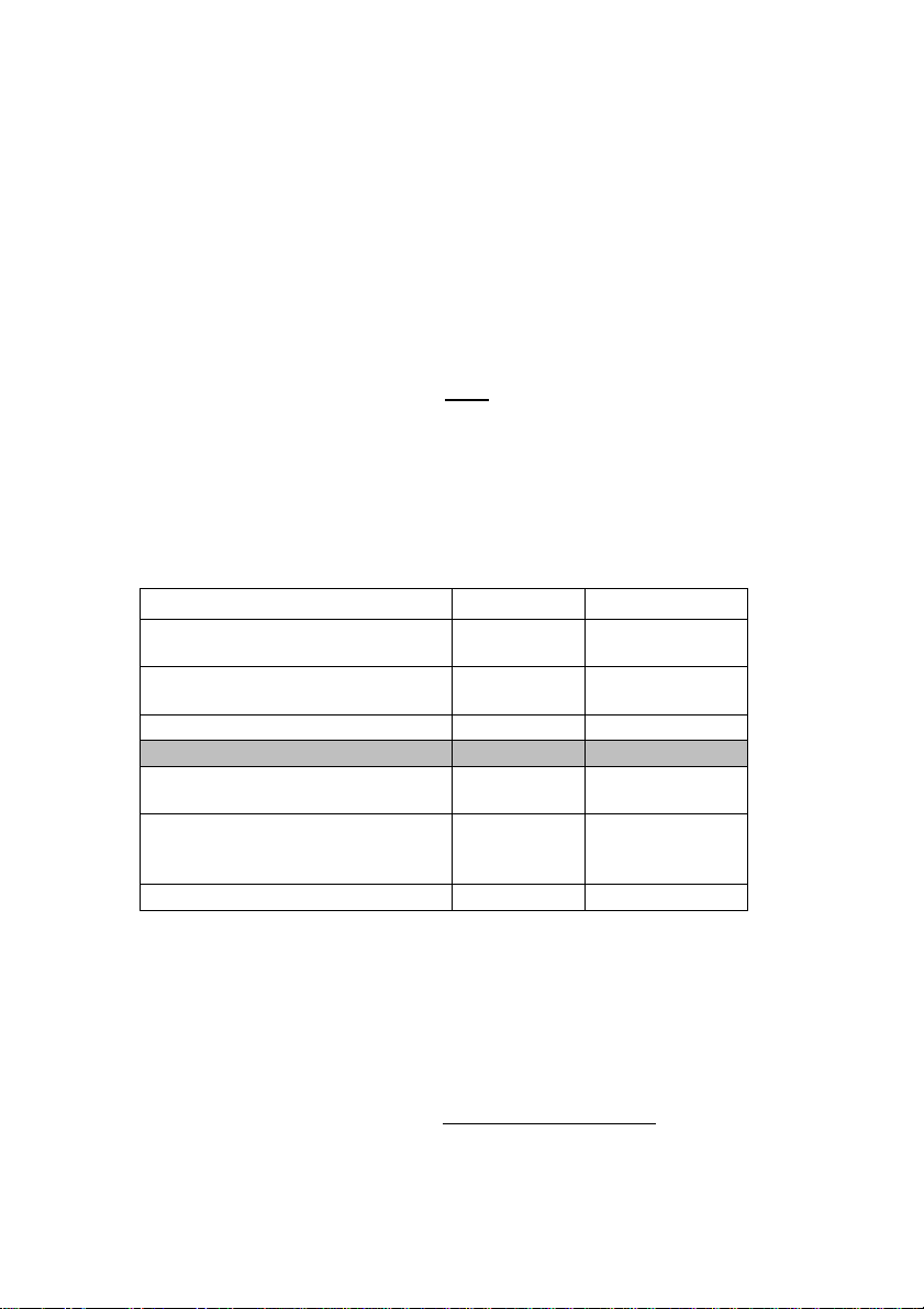
The table below shows the typical” calibration you would use, depending on how the
tacho signal is connected and the engine configuration.
Connection Type Calibration Display Setting
Coil-on-Plug.
Coil per spark plug. 0 5 1 light flashing
Wasted spark coil.
Instrument tacho signal. 1 1 light on
Usually only for 3 cylinder engine. 1 5 1 light on, 1 flashing
Instrument tacho signal. <factory default> 2 2 lights on
Usually only for 3 or 5 cylinder engines 2 5
3
2 lights on, 1 flashing
3 lights on
Distributor coil.
Instrument tacho signal.
4
6
8
4 lights on
6 lights on
All lights on
Usually only for 5 or 10 cylinder engines. 5 5 lights on
Changing the Calibration Value
To change the Calibration value, you need to enter the calibration setting mode. With
the ignition off, press and hold both buttons, turn the ignition on and then release the
buttons. If it is the first time you have entered this mode, you will see the first two lights
are illuminated, indicating the default value of 2 (shaded row in table above). Press up
or down to change the settings, and then press both buttons to save. You can re-enter
the calibration mode to verify it was saved. You don’t need to switch the ignition off,
just start the engine and try the new setting.

7
Unsure which Calibration value to use? Start the engine and see if you get the
lights coming on at 1000, 2000, 3000rpm etc… If the lights are coming on too soon,
increase the calibration. If they are not turning on or you have to rev the RPM too high,
reduce the calibration.
TIPS:
•When you first turn on ignition, it will display battery voltage. This will normally revert to
RPM mode a couple of seconds after the engine has started. To have it in RPM display
mode straight away, press a button to exit battery mode (ONLY before starting the
engine).
•Unless you have an odd cylinder engine, you should not need 1.5, 2.5, 3 or 5.
•If the display flickers with the RPM, reduce the sensitivity first (see previous section
regarding verifying tacho signal connected).
•The Shift-I responds to RPM increasing very quickly. Often it’s considerably faster and
more accurate than the instrument tacho gauge. Which means it may respond before the
gauge needle does. Once a light turns on, the RPM has to drop a certain amount before it
will turn off. This is a configurable feature, quite an important useful one. Later, once you
have the RPM display range set, you won’t notice it.
RPM Set-Points
You can set when the first light turns on (Lower Set-Point), and also when they flash
(Upper Set-Point). The lights in between are automatically calculated. This section
advises how to adjust the set-points.
With ignition on, press and hold the Up button. After a couple of seconds the display
will change. The lights at the right side are used to represent the value of the Upper
RPM set-point. To read the value, count how many times each light flashes. Each
light represent a digit. For example, a value of 12,500rpm would flash the left most
light once (1), the next one twice (2), the third one 5 times (5) and the remaining two
won’t flash (0) & (0). You then have the number 12500. The flash sequence repeats,
so if you miss it the first time, wait for the pause and count again.
Press up or down to increase or decrease the value, then press both buttons at once to
save your changes (or blip the engine over 2,200rpm to save). Setting the lower RPM
set-point is similar, except press and hold the Down button instead. The lights used
are now on the left hand side. More detail on this topic can be found on page 5 of the
User Manual.
You can change these settings while the engine is idle (<2,200rpm), so you can
conveniently make an adjustment and test it. But not while driving!
You will initially only be able to increase/decrease the settings in one thousand
intervals. Once you have the range set roughly where you want it, have a look at page
9 of the User Manual. It will tell you how to change it so you can change this to a finer
resolution, such as increasing and decreasing in steps of 100rpm.
8
MOUNTING THE DISPLAY
Included is a high performance acrylic adhesive foam pad, which has excellent
resistance to ageing, water, most solvents and UV light. They stick really well to plastic,
but not to vinyl (particularly those with protective waxes applied). They can be safely
removed, however if in doubt, first test an area with a small piece in an appropriate
place. Clean the surfaces before applying the adhesive pads.
Immediately after application, they can be removed or re-positioned without great effort.
The pads take a couple of days to achieve the maximum bond strength, after which,
they will most likely tear apart before coming off. Usually the remains can be rubbed
off (without leaving a residue), and without any chemicals.
The Shift-I™ must be mounted behind a windscreen, where it is not subjected to the
wind pressure or rain. Choose a place to mount the unit where the lights are clearly
visible and it do not interfere or obstruct the drivers view. Do not place it in a location
where the headlights from another vehicle are incident on the display, as the light
sensor will assume it is daylight and automatically increase the brightness. Test the
brightness level is suitable in both light and dark conditions, and adjust as required (see
User Manual, page 8).
Ground
=
Black
Ignition = Black / Red
Tacho = Black / Blue
www.ecliptech.com.au
Table of contents
Other Ecliptech Automobile Accessories manuals


