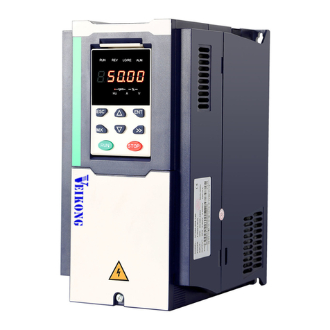
Eco Drive V5-H Series User manual

V&T Technologies Co., Ltd. http://www.ecodrivecn.com
Foreword
The V5−H series inverter is a kind of high-performance vector control inverter
provided by V&T Technologies Co., Ltd. The product adopts speed sensorless
vector control technology technology, the internationally leading technology, to
offer excellent control performance and combines the application
characteristics of China to further enhance the product reliability, environment
adaptability and customized and industrialized design. It can better meet the
demands of the various drive applications.

V&T Technologies Co., Ltd. http://www.ecodrivecn.com
Excellent Performance
Control Mode
Vector Control 1:
Offering excellent vector control performance and insensitive to motor parameters.
Startup torque: 0.50Hz 180% rated torque
Speed adjustment range: 1:100
Speed stabilization precision: ± 0.5%
0.50Hz controlble motor stable operation with 150% rated torque
Vector Control 2:
Precise speed sensorless vector control technology realizes AC motor decoupling,
enabling the DC motorization of operation control.
Startup torque: 0.25Hz 180% rated torque
Speed adjustment range: 1:200
Speed stabilization precision: ± 0.2%
Excellent Control Performance under Speed Sensorless Vector
Control Mode
Realizing AC motor decoupling, enabling the DC motorization of operation control.
Fig. 1 indicates the four-quadrant operation of the motor under speed sensorless vector
control. The torque, current, speed and DC bus voltage have quick response, and the
motor has stable operation.
Realizing 0.1s acceleration/deceleration with rated motor load.
Upon the zero-crossing switching of the motor (forward/reverse switching), the current
has no phase mutation or oscillation, and the rotating speed has no pulsation.
The bus voltage is under stable control. Quick and reliable braking can be realized
when decelerating under the condition of braking without power consumption.
It is especially suitable for:
The reciprocating equipment, such as numerical control machine, fountain control
machine, weaving machine and jacquard.

V&T Technologies Co., Ltd. http://www.ecodrivecn.com
Fig. 1 Quick acceleration/deceleration four-quadrant running in the form of 0Hz
→Forward running 50Hz→0Hz→Reverse running 50Hz→0Hz
Realizing Real Tripless Operation
With excellent current and voltage control technology, 0.1s repetitive and alternate
acceleration and deceleration is performed, and the inverter realizes stable and tripless
operation.
With extremely powerful loading capability, the inverter can realize stable tripless
operation in any acceleration/deceleration time and under any impact load condition.
With strong short-time overload capability, the inverter can operate continuously for
0.5s under 200% rated load, and 1 minute under 150% rated load.
The intelligent module temperature control maximizes the loading capability of the
inverter.
It is especially suitable for:
The heavy-duty equipment, such as injection molding machine (modification for energy
saving), lifting equipment, numerical control machine, rolling mill, furnace feeding
equipment.
Speed
Current
Bus voltage
Torque

V&T Technologies Co., Ltd. http://www.ecodrivecn.com
Fig. 2 The inverter realizes stable control of current and voltage and
will not trigger under any acceleration/deceleration condition
as well as stable operation condition
Large Torque and Stable Operation at Low Frequency under Vector
Control
With precise speed identification and rotor magnetic flux orientation, the torque
responds quickly and stable operation in the case of 0.25Hz load mutation.
Startup torque: Open loop vector control: 0.25Hz; 180% rated torque
Speed stabilization precision: Open loop vector control: ±0.2%
It is especially suitable for:
Medium and large wire-drawing machine, pipe and cable processing, lifting equipment,
rolling mill.
Fig.3 Abrupt increase to full load operation at
0.25Hz under speed sensorless vector control
Current
B
us voltage
Current

V&T Technologies Co., Ltd. http://www.ecodrivecn.com
Unique Instantaneous Mains Failure Reaction
Upon the instantaneous mains failure, the energy of the motor feedback bus will keep
the inverter running till the mains resumes normal.
When shutdown is caused by long-term power-failure during the operation of the
inverter, the inverter will provide alarm message after power resumes normal.
It supports the automatic operation after power-up.
The deceleration time during the power failure and the acceleration time after the
power recovery can be set independently.
It is especially suitable for:
Instantaneous power-failure startup equipment, such as chemical fiber and weaving
equipment, multi-point synchronization linkage equipment, fan/pump, etc.
Unique Speed Tracing Function
It doesn’t need special hardware detection circuit and no special function code to be set.
Within the range of 0 to 60Hz, the inverter can complete identification the motor rotating
speed, rotating direction and phase angle within 0.2s, and start smooth tracing on the
freely rotating motor.
Tracing mode 1: Quick and smooth tracing on the free speed motor without any impact.
It is especially suitable for:
The equipment whose operation shall be traced upon the power recovery after
instantaneous power failure, such as fan and pump.
Fig. 4 Quick and impactless rotating speed tracing upon the motor free rotation
Current
Rotating speed

V&T Technologies Co., Ltd. http://www.ecodrivecn.com
Tracing mode 2: Impactlessly pull down the motor from high-speed to low speed and
then accelerate to normal speed.
Fig. 5 Tracing and smooth startup after frequency reduction upon the motor high-speed
free rotation
Unique Quick DC Braking
Within the range of 0 to 300Hz, the inverter can realize back electromotive force
elimination and quick DC braking within 0.3s.
DC current input in the most efficient way to improve the braking capability.
There is no initial waiting time for the DC braking.
Special function code of the initial waiting time for DC braking setting is cancelled.
It is especially suitable for:
Lifting equipment, invertible roll table for rolling mill, weaving machine, paper making
production line.
Current
Rotating speed

V&T Technologies Co., Ltd. http://www.ecodrivecn.com
High Reliability Design
Meeting the Relevant International Product Standards
IEC61800-2 General requirements–Rating specifications for low voltage adjustable
frequency a.c. power drive systems
IEC61800-3 EMC product standard including specific test methods
IEC61000-6 Electromagnetic compatibility (EMC) –Part6: Generic standards
IEC61800-5-1 Safety requirements –Electrical, thermal and energy
UL508C UL Standard for Safety for Power Conversion Equipment
Integrated Design
Integrated design of hardware interface: The control board, button/shuttle type
operation panel are integrated to facilitate the operation and maintenance of the
user.
Integrated design of software protocol: Terminal/operation panel 485, universal
expansion port SPI protocols are integrated (Modbus protocol).
Integrated design of main circuit terminals: 0.75G to 15G integrated, 18.5G to 75G
integrated, 90G to 500G integrated, to facilitate the operation and maintenance of
the user.
Built-in braking unit design: 0.75G to 15G as standard, 18.5G to 75G as option, to
reduce the cost and the installation space.
Integrated built-in expansion card design: including injection molding machine
interface card/PG feedback card/communication adapter card, meeting the industry
application requirement.
Full series standard common DC bus design: The standard common DC bus
scheme can be realized without modifying the product or adding peripheral circuit. It
is applicable to such industry applications as paper making, chemical fiber,
metallurgy and EPS.
Adaptability Design
Independent duct design: The full series supports the application demand of
mounting heatsink out of the cabinet, and is applicable to the applications of spinning
machine, wire-drawing machine where there is too much cotton batting or dust.
Compact structure design: With complete thermal emulation and unique cold plate
process, the product has compact structure, meeting the demands of OEM
customers.
Complete system protection design: Based on the complete system design scheme,
the PCB adopts protective coating, the copper bus adopts galvanization, the full
series of product adopts sealed key components, the button and shuttle type
operation panels can offer accessories meeting the IP54 requirement, which greatly

V&T Technologies Co., Ltd. http://www.ecodrivecn.com
improve the protection capability of the system. It is applicable to the applications
with dusty and corrosive environment, such as wire-drawing machine, printing and
dyeing and ceramics.
Wide voltage range design: the DC operating voltage range is DC 360−720V, with
mains voltage fluctuation recording function.
Precise current detection and protection: The full series adopts precise Hall sensor
to detect the output current, meeting the quick real time control and protection
requirement of software and hardware, ensuring the performance and reliability of
the system.
Independent power supply for control: The system provides independent switching
power DC input port. External UPS power supply can be realized through option
card. It is applicable to the applications of oilfield, chemical industry and printing and
dyeing industry.
Power-up self-detection function: It realizes the power-up detection on the peripheral
circuit, such as motor grounding, disconnection, greatly improving the reliability of
the system.
Comprehensive system protection function: software/hardware current limiting
protection, overcurrent and overvoltage protection, grounding short circuit protection,
overload protection, IGBT short circuit protection, abnormal current detection
protection, abnormal relay contact protection.
Perfect terminal protection function: short circuit and overload protection for the
+24V and +10V power supply of the control terminal, operation panel cable reverse
connection protection, input signal cable disconnection and abnormal analog input
protection.
Over-temperature prealarm protection function: Automatic adjustment will be made
according to the temperature to ensure the reliable operation of the product, and
maximum operating temperature will be recorded.
Comprehensive switching power protection function: including switching power
output short circuit protection, overload protection, power-up walk-in function, open
loop self-locking and voltage limiting protection function, ensuring the reliability of the
system.

V&T Technologies Co., Ltd. http://www.ecodrivecn.com
Rich and Flexible Functions
Multiple Frequency Reference Modes, Flexible and Convenient for
Operation
Operation panel reference (digital reference). The operation panel can be used to
conduct ∨/∧ adjustment on the frequency reference.
Terminal reference:
1) Analog AI1/AI2: 0 to 10V or 0 to 20mA
2) Analog AI3: -10V to 10V
3) Pulse frequency X7/DI: 0.2Hz to 50kHz
4) Xi terminal: UP/DN mode independent, able to superpose with any other
frequency reference mode
Communication mode reference: International standard Modbus protocol.
The above reference modes can be switched online.
Multiple Channels for Reference and Feedback
Under the open loop mode and analog feedback close loop mode, the reference value
can define the main and auxiliary calculation relation:
1) Main reference + auxiliary reference
2) Main reference - auxiliary reference
3) Main reference + auxiliary reference -50%
4) Max (main reference, auxiliary reference)
5) Min (main reference, auxiliary reference)
The sign of the main and auxiliary reference calculation (positive or negative) can
automatically determine the rotation direction of the motor.
Under the analog feedback close loop mode, the feedback value can also define the
main and auxiliary calculation relation before it enters the process PID for adjustment
control.
It is especially suitable for:
The continuous and automatic production lines, such as paper making, printing and
dyeing, packaging and printing.
The temperature difference and pressure difference applications, such as the chilled
water control of the central air conditioner, the water supply system.
Digital Operation Panel
Button type and shuttle type selectable, RS485 communication mode, standard
network port connection.
The button layout complies with the human engineering principle. One-button function
code access and exit, making it easy for the operation.
The standard configuration operation panel can realize parameter copy and remote
control function (maximum length: 500m).

V&T Technologies Co., Ltd. http://www.ecodrivecn.com
With unique multifunctional button M, the following functions can be defined:
1) JOG
2) Emergency shutdown 1 (fastest shutdown)
3) Emergency shutdown 2 (free shutdown)
4) Reference mode switch through operating command (operation panel reference
→terminal reference→host computer reference →operation panel reference)
5) FASt/bASE menu switch
6) Menu mode switching (bASE→FASt→ndFt→LASt→bASE)
Host Computer Communication
The operation panel and terminals provide 485 ports, the communication protocol is
Modbus, and host computer monitoring software is provided.
Master slave communication control among several inverters can be realized.
Parameter upload and download can be realized.
Cascade transmission of operating frequencies for several inverters can be realized to
provide digital frequency divider functions.

V&T Technologies Co., Ltd. http://www.ecodrivecn.com
Customized Functions
Multiple Function Code Display Modes
bASE: Basic menu mode (refer to 5.1 basic menu function code parameter table),
displays all the function codes.
FASt: Fast menu mode, is especially suitable for the naive users.
ndFt: Non-leave-factory value menu mode, it only displays the function codes different
from the leave-factory values to facilitate the inquiry and commissioning.
LASt: Last change menu mode, it displays the 10 functions codes that are recently
changed and P0.02 to facilitate the inquiry and commissioning.
The users can define the function codes for inquiry and modification by themselves.
Multiple Function Code Encryption Modes (to Protect the Intellectual
Property of the Customers)
The user can encrypt any group function codes by themselves.
The user can lock operation panel.
The user can set function parameter password protection.
The technical secrets, such as system specific process parameters, cannot be copied.
User Self-defined Parameter Display Function
The user can choose the common parameters displayed by the operation panel and
use to >> key switch such parameters.
The user can define the parameters displayed upon running and stopping respectively.
The user can define such parameters as pressure, temperature, flux and line speed.
The User can Make Secondary Development
Universal expansion port is provided as standard.
Physical port SPI bus, software protocol Modbus.
The ports provide +24V, ±15V and 5V power supply and two ways of A/D input.
The CPU expansion scheme can realize PLC function.
It supports the programming by user to realize process control.
Enhanced Function
The software filtering time for the AI1, AI2 and AI3 analog input is settable to enhance
the anti-interference capability.
Independent multi-section modification can be made on theAI1, AI2, AI3 and DI analog
input curve.
Multi-section speed setting is provided, with 16 speeds as standard, and up to 23
speeds.
With a maximum output frequency of 3000Hz, it is applicable to such equipment as

V&T Technologies Co., Ltd. http://www.ecodrivecn.com
vacuum pump, grinding machine, female thread extrusion machine.
With the acceleration/deceleration time up to 10 hours, it is applicable to the bobbiner
and other equipment of the textile industry.
It supports the overload protection with motor temperature feedback.
Customized timed shutdown, with the duration up to 100 hours.
The user can select button type or shuttle type operation panel according to their
preference.
Independent high-speed pulse input and output ports are provided to realize
high-speed pulse cascade function.

V&T Technologies Co., Ltd. http://www.ecodrivecn.com
Typical industry applications
Digital Control Machine Tool
Compact structure: The size is equal to 70% of the inverter of the same power.
Low speed precise processing: The excellent low-frequency torque performance can
meet the processing demand of the machine main shaft in low speed condition (when it
is operating in motoring state, it can realize a frequency as low as 0.25Hz and output
180% rated torque).
Torque and rotating speed index: It can meet the sudden loading and unloading
requirement upon the cutting processing, with the dynamic torque response time
<20ms and speed stabilization precision of ±0.2%.
Special Function for Wire-drawing Machine
Operation without swing link: It adopts open loop tension control to realize operation
without swing link under speed sensorless control mode.
Operation with swing link: The user does not need to adjust the position of the swing
link manually. When the system starts up, the swing link will get to the proper position
automatically.
Powerful tensile capability: It is suitable for the applications of large and medium
wire-drawing machine. It features large torque upon low frequency operation and high
speed stabilization precision.
Double conversion scheme: It can realize the inverter application of the same power
class with precise current control and does not need to upgrade the level.
Environment adaptability: Independent duct design, protective coating treatment,
high-temperature operation, and digital protection function.
Special Function for Textile
Traverse operation function: It can effectively lead the yarn into the yarn carrier on the
yarn and chemical fiber equipment to prevent the overlapping of the yarn and facilitate
the unreeling.
Constant line speed mode: It can effectively prevent the uneven tightness of the yarns
from the high speed cone winder to maintain the constant tension.
Fixed length calculation: It is convenient for the user to calculate the thread length.
When the thread length reaches the preset value, the equipment will be shut down
automatically.
Fixed diameter shutdown: The spindle diameter can be detected by inputting analog
signal. When the preset value is reached, the equipment will be shut down
automatically.
Crawling positioning: When the spinning is interrupted or ended, it can decelerate the
equipment to designated frequency for low-speed operation and then shut down the

V&T Technologies Co., Ltd. http://www.ecodrivecn.com
equipment when receiving the positioning signal.
Extrusion Machine Energy Saving
Extrusion machine interface board: It can realize best flow and pressure distribution
relation in different processes by receiving the extrusion machine feedback signal to
realize the optimized energy saving control of the motor.
Customized process curve: The user does not need to change the inverter parameter
when replacing the moulds. The process curve memory can be easily realized.
Wide range torque output: Within the set range of pressure and flow, the motor torque
output is stable to ensure the quality of the workpiece.
Tripless: With extremely powerful loading capability, the inverter can realize stable
tripless operation in any acceleration/deceleration time and under any impact load
condition.
Green output: It adopts advanced power module drive mode to reduce the interference
to the extrusion machine control circuit and sensor.
Lifting Control
Step torque response: It can quickly follow the equipment load change to prevent the
runaway situation and ensure the safe production.
Four quadrant operations: It can smoothly and quickly switch the forward and reverse
motoring and generating state of the equipment.
Torque monitoring: It can adjust, limit, display and switch the torque output, so as to
monitor the operating state of the equipment.

V&T Technologies Co., Ltd. http://www.ecodrivecn.com
Safety Precautions
Description of safety marks:
Danger: The misuse may cause fire, severe injury, even death.
Note: The misuse may cause medium or minor injury and equipment damage.
Use
DangerDanger
This series of inverter is used to control the variable speed operation of three-phase
motor and cannot be used for single-phase motor or other applications. Otherwise,
inverter failure or fire may be caused.
This series of inverter cannot be simply used in the applications directly related to the
human safety, such as the medical equipment.
This series of inverter is produced under strict quality management system. If the
inverter failure may cause severe accident or loss, safety measures, such as
redundancy or bypass, shall be taken.
Goods Arrival Inspection
NoteNote
If the inverter is found to be damaged or lack parts, the inverter cannot be installed.
Otherwise, accident may be caused.
Installation
NoteNote
When handling and installing the product, please hold the product bottom. Do not hold
the enclosure only. Otherwise, your feet may be injured and the inverter may be
damaged because of dropping.
The inverter shall be mounted on the fire retardant surface, such as metal, and kept far
away from the inflammables and heat source.
Keep the drilling scraps from falling into the inside of the inverter during the installation;
otherwise, inverter failure may be caused.
When the inverter is installed inside the cabinet, the electricity control cabinet shall be
equipped with fan and ventilation port. And ducts for radiation shall be constructed in
the cabinet.

V&T Technologies Co., Ltd. http://www.ecodrivecn.com
Wiring
DangerDanger
The wiring must be conducted by qualified electricians. Otherwise, there exists the risk
of electric shock or inverter damage.
Before wiring, confirm that the power supply is disconnected. Otherwise, there exists the
risk of electric shock or fire.
The grounding terminal PE must be reliably grounded, otherwise, the inverter enclosure
may become live.
Please do not touch the main circuit terminal. The wires of the inverter main circuit
terminals must not contact the enclosure. Otherwise, there exists the risk of electric
shock.
The connecting terminals for the braking resistor are⊕2/B 1 and B 2. P lease do not
connect terminals other than these two. Otherwise, fire may be caused.
The leakage current of the inverter system is more than 3.5mA, and the specific value of
the leakage current is determined by the use conditions. To ensure the safety, the
inverter and the motor must be grounded.
Wiring
NoteNote
The three-phase power supply cannot connect to output terminals U/T1, V/T2 and
W/T3, otherwise, the inverter will be damaged.
It is forbidden to connect the output terminal of the inverter to the capacitor or LC/RC
noise filter with phase lead, otherwise, the internal components of the inverter may be
damaged.
Please confirm that the power supply phases, rated voltage are consistent with that of
the nameplate, otherwise, the inverter may be damaged.
Do not perform dielectric strength test on the inverter, otherwise, the inverter may be
damaged.
The wires of the main circuit terminals and the wires of the control circuit terminals shall
be laid separately or in a square-crossing mode, otherwise, the control signal may be
interfered.
The wires of the main circuit terminals shall adopt lugs with insulating sleeves.
The inverter input and output cables with proper sectional area shall be selected
according to the inverter power.
When the length of the cables between the inverter and the motor is more than 100m, it
is suggested to use output reactor to avoid the inverter failure caused by the overcurrent
of the distribution capacitor.
The inverter which equipped with DC reactor must connect with DC reactor between the
terminal of ○
+1、○
+2, otherwise the inverter will not display after power on.

V&T Technologies Co., Ltd. http://www.ecodrivecn.com
Operation
DangerDanger
Power supply can only be connected after the wiring is completed and the cover is
installed. It is forbidden to remove the cover in live condition; otherwise, there exists the
risk of electric shock.
When auto failure reset function or restart function is set, isolation measures shall be
taken for the mechanical equipment, otherwise, personal injury may be caused.
When the inverter is powered on, even when it is in the stop state, the terminals of the
inverter are still live. Do not touch the inverter terminals; otherwise electric shock may
be caused.
The failure and alarm signal can only be reset after the running command has been cut
off. Otherwise, personal injury may be caused.
NoteNote
Do not start or shut down the inverter by switching on or off the power supply, otherwise,
the inverter may be damaged.
Before operation, please confirm if the motor and equipment are in the allowable use
range, otherwise, the equipment may be damaged.
The heatsink and the braking resistor have high temperature. Please do not touch such
device; otherwise, you may be burnt.
When it is used on lifting equipment, mechanical contracting brake shall also be
equipped.
Please do not change the inverter parameter randomly. Most of the factory set
parameters of the inverter can meet the operating requirement, and the user only needs
to set some necessary parameters. Any random change of the parameter may cause
the damage of the mechanical equipment.
In the applications with industrial frequency and variable frequency switching, the two
contactors for controlling the industrial frequency and variable frequency switching shall
be interlocked.
Maintenance, Inspection
DangerDanger
In the power-on state, please do not touch the inverter terminals; otherwise, there exists
the risk of electric shock.
If cover is to be removed, the power supply must be disconnected first.
Wait for at least 10 minutes after power off or confirm that the CHARGE LED is off
before maintenance and inspection to prevent the harm caused by the residual voltage
of the main circuit electrolytic capacitor to persons.
The components shall be maintained, inspected or replaced by qualified electricians.

V&T Technologies Co., Ltd. http://www.ecodrivecn.com
NoteNote
The circuit boards have large scale CMOS IC. Please do not touch the board to avoid
the circuit board damage caused by electro static.
Others
DangerDanger
It is forbidden to modify the inverter unauthorizedly; otherwise, personal injury may be
caused.

V&T Technologies Co., Ltd. http://www.ecodrivecn.com
Contents
Chapter 1 Introduction to V5-H Series Inverter..................................................................................1
1.1 Product Model Description..................................................................................................................1
1.2 Product Nameplate Description..........................................................................................................1
1.3 Product Series....................................................................................................................................2
1.4 Technical Specifications of Product.....................................................................................................4
1.5 Product Component Name.................................................................................................................6
1.6 Product Outline, Mounting Dimension, and Weight .............................................................................6
1.7 Operation Panel Outline and Mounting Dimension..............................................................................9
1.8 Pallet Outline and Mounting Dimension..............................................................................................9
1.9 Braking Resistor Lectotype...............................................................................................................10
Chapter 2 Inverter Installation...........................................................................................................11
2.1 Environment for Product Installation .................................................................................................11
2.2 Mounting Direction and Space..........................................................................................................11
2.3 Removal and Mounting of Operation Panel and Cover......................................................................12
Chapter 3 Wiring of Inverter..............................................................................................................16
3.1 Connection of the Product and Peripheral Devices...........................................................................16
3.2 Description of Peripheral Devices for Main Circuit.............................................................................17
3.3 Lectotype of mMain Circuit Peripheral Devices.................................................................................17
3.4 Product Terminal Configuration.........................................................................................................19
3.5 Functions of Main Circuit Terminal....................................................................................................19
3.6 Attention for Main Circuit Wiring........................................................................................................20
3.7 Terminal Wiring ................................................................................................................................24
3.8 Functions of Control Circuit Terminals...............................................................................................25
3.9 Schematic Diagram of Control Board................................................................................................28
3.10 Lectotype of Control Circuit Peripheral Devices ..............................................................................29
3.11 Description of Jumper Function.......................................................................................................29
Chapter 4 Using Instructions of Operation Panel ............................................................................30
4.1 Introduction to Operation Panel........................................................................................................30
4.2 Descriptions of Indicators .................................................................................................................30
4.3 Description of Keys on Operation Panel............................................................................................31
4.4 Menu Style.......................................................................................................................................32
4.5 Password Operation.........................................................................................................................37
4.6 Lock/Unlock Keys.............................................................................................................................38
4.7 Operation Panel Display and Key Operation.....................................................................................39
4.8 Operation Example...........................................................................................................................40
4.9 Running for the First Time ................................................................................................................41
Chapter 5 List of Parameters ............................................................................................................43
5.1 List of Basic Menu Function Codes...................................................................................................43

V&T Technologies Co., Ltd. http://www.ecodrivecn.com
5.2 User’s Parameter Record.................................................................................................................60
5.3 User’s Connection Diagram..............................................................................................................61
Chapter 6 Parameter Description......................................................................................................62
6.1 Basic Function Parameter (Group P0)..............................................................................................62
6.2 Main and Auxiliary Reference Parameter (Group P1)........................................................................67
6.3 Key and Display Parameters (Group P2)..........................................................................................71
6.4 Startup/stop Parameter (Group P3) ..................................................................................................74
6.5 Multi-section Parameter (Group P4) .................................................................................................76
6.6 Multi-functional Input Parameter (Group P5).....................................................................................79
6.7 Analog Reference Parameter (Group P6) .........................................................................................86
6.8 Multi-function Output Parameter (Group P7).....................................................................................90
6.9 Process PID Close Loop Parameters (Group P8) .............................................................................96
6.10 Motor Parameter (Group P9)..........................................................................................................98
6.11 Control Parameter (Group PA)......................................................................................................102
6.12 Enhanced Function Parameter (Group Pb)...................................................................................108
6.13 Communication Parameters (Group PC).......................................................................................112
6.14 Vector Control 2 Parameters (Group Pd) ......................................................................................113
6.15 Failure Record Parameters (Group d0).........................................................................................117
6.16 Product Identity Parameters (Group d1)........................................................................................117
6.17 Use of Display Parameters (Group d2).........................................................................................119
Chapter 7 Fault Diagnosis...............................................................................................................121
7.1 List of Fault and Alarm Information .................................................................................................121
7.2 Troubleshooting Procedures...........................................................................................................127
Chapter 8 Routine Repair and Maintenance .....................................................................................128
8.1 Routine Maintenance .....................................................................................................................128
8.2 Periodic Maintenance.....................................................................................................................129
8.3 Component Replacement...............................................................................................................129
8.4 Insulation Test................................................................................................................................129
Appendix A Modbus Communication Protocol..............................................................................131
Appendix B Control Mode Setting Process....................................................................................140
1. Setting Process for Auto-tuning ........................................................................................................140
2. Setting Process for Open Loop.........................................................................................................141
3. Setting Process for Closed Loop ......................................................................................................143
Appendix C FAQ..............................................................................................................................146
Table of contents
Other Eco Drive Inverter manuals
