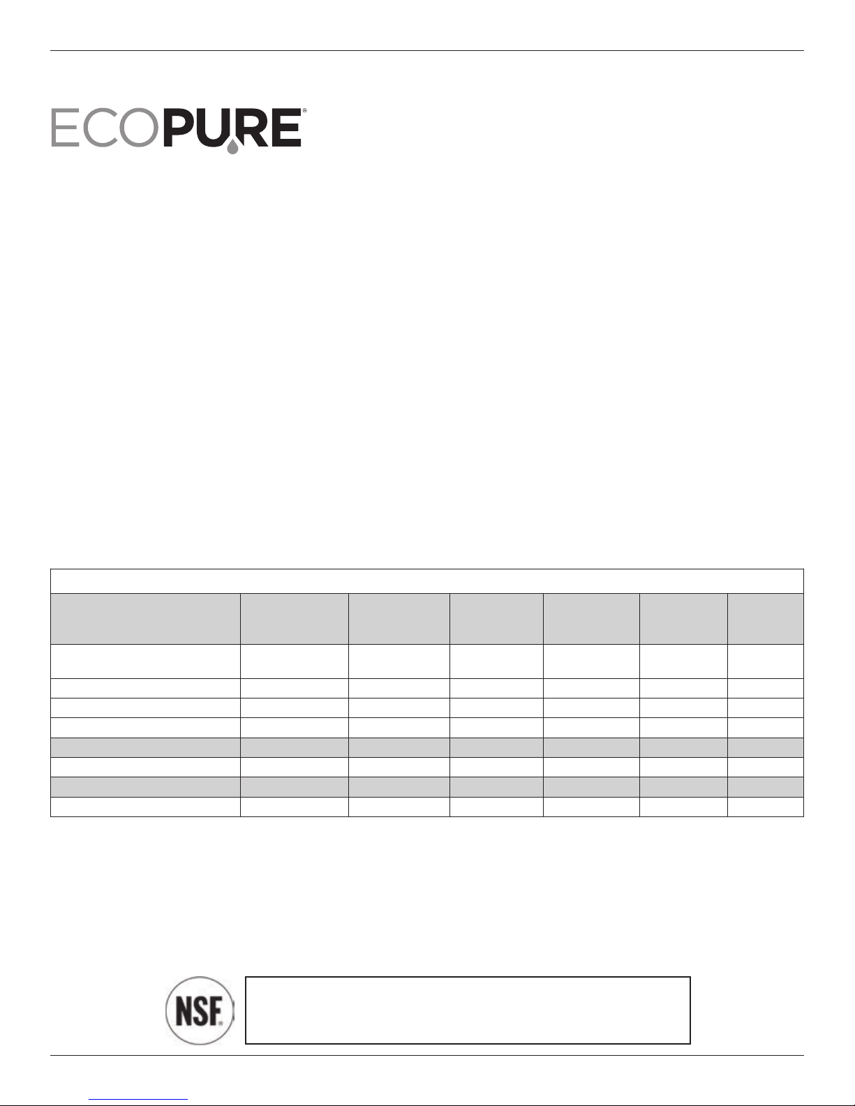
Eco Pure ECOP20 User manual

7316151 (Rev. L 1/2/18)
Installation and Operation Manual
Manufactured and warranted by
Ecodyne Water Systems
1890 Woodlane Drive
Woodbury, MN 55125
How to install, operate
and maintain your Undersink
Drinking Water System
Model E OP20
System tested and certified by NSF International
against NSF/ANSI Standards 42 & 53. See
performance data on pages 11 & 12 for details.
If you have any questions or concerns when
installing, operating or maintaining your water
filtration system, call our toll free number:
1-800-693-1138
or visit www.ecopure.com
When you call, please be prepared to provide
the model number and date code of
your product, found inside the top cover.
PR DUCT AND WARRANTY
REGISTRATI N
Register your product
online to validate and
extend your warranty.
See warranty page for
details.
www.ecopure.com

2
Questions? all toll free: 1-800-693-1138
3-1/2"8-3/8"
13"
FFiFilFiltFilteFilterFilterFilter 1Filter 1 FFilter 1 FiFilter 1 FilFilter 1 FiltFilter 1 FilteFilter 1 FilterFilter 1 FilterFilter 1 Filter 2Filter 1 Filter 2
3-1/2”
13”
8-3/8”
Table of Contents
Parts of the System / Materials and Tools Needed / Typical Undersink Installation . . . . . . . . . . . . . . . . . 3
Installation Steps . . . . . . . . . . . . . . . . . . . . . . . . . . . . . . . . . . . . . . . . . . . . . . . . . . . . . . . . . . . . . . . . . . 4-6
Filter artridge Life / Filter artridge Replacement . . . . . . . . . . . . . . . . . . . . . . . . . . . . . . . . . . . . . . . . . 7
Faucet Timer / Battery hange . . . . . . . . . . . . . . . . . . . . . . . . . . . . . . . . . . . . . . . . . . . . . . . . . . . . . . . . . 8
Troubleshooting the System . . . . . . . . . . . . . . . . . . . . . . . . . . . . . . . . . . . . . . . . . . . . . . . . . . . . . . . . . . . 8
Repair Parts . . . . . . . . . . . . . . . . . . . . . . . . . . . . . . . . . . . . . . . . . . . . . . . . . . . . . . . . . . . . . . . . . . . . . . . 9
Warranty . . . . . . . . . . . . . . . . . . . . . . . . . . . . . . . . . . . . . . . . . . . . . . . . . . . . . . . . . . . . . . . . . . . . . . . . . 10
Performance Data . . . . . . . . . . . . . . . . . . . . . . . . . . . . . . . . . . . . . . . . . . . . . . . . . . . . . . . . . . . . . . . 11-12
Before You Start
qRead all steps and guides carefully before installing and using your undersink drinking water filter sys-
tem. Follow all steps exactly to correctly install. Reading this manual will also help you to get all the ben-
efits from the undersink drinking water filter system.
qDo not use with water that is microbiologically unsafe or of unknown quality without adequate disinfec-
tion before or after the system. This system is certified for cyst reduction and may be used on disinfected
waters that may contain filterable cysts.
qAll plumbing should be done in accordance with local codes and requirements. In Massachusetts,
plumbing code 248 MR 3.00 and 10.00 shall be adhered to. onsult with your licensed plumber.
qThe undersink drinking water filter system works on water pressures of 30 psi (minimum) to 100 psi
(maximum). If your house water pressure is over the maximum, install a pressure reducing valve in the
water supply pipe to the filter system.
qDo not install the undersink drinking water filter system outside, or in extreme hot or cold tempera-
tures. Temperature of the water supply to the undersink drinking water filter system must be between
40°F and 100°F. Do not install on hot water.
Min. - Max. Supply Water Pressure 30 - 100 psi (207 - 689 kPa)
Min. - Max. Supply Water Temperature 40 - 100 °F (4 - 38 ° )
Inlet - Outlet 3/8" quick connect fittings and tubing included
Specifications and Dimensions

3
Questions? all toll free: 1-800-693-1138
Parts of the System
Materials and Tools Needed
Typical Undersink Installation
• filter system assembly
• water supply fitting
• filtered water faucet for sink or countertop mounting
• 3/8" tubing to make all needed connections
N TE: Gather the required tools before starting installation. Read and follow
the instructions provided with any tools listed here.
• slotted and Phillips screwdrivers
• pliers and adjustable jaw wrench
• tubing cutter
• electric drill and 1-1/4" drill bit if mounting hole is needed for the faucet
IMP RTANT: To avoid damaging the sink, consult a qualified plumber or
installer for drilling procedures in porcelain or stainless steel.
Locate the water filter housing on the cold water supply pipe, under the kitchen and/or bathroom sink, to
filter the cold drinking water. Refer to the following drawing.
shutoff valve
filtered water
faucet
Filter 2
(post filter)
Filter 1
(pre filter)
Blue
WATER
UT
Yellow
WATER
IN
water supply
fitting
SINK
N TE: Be sure to allow a minimum space of 1-1/2" under the system
for removing the filter cartridges, in order to change the cartridges.
Fig. 1
4-1/4”
HOT OLD

4
Questions? all toll free: 1-800-693-1138
Installation Steps
Step 1 - old Water Supply Fitting
Fig. 2
A. Water supply connection
(using included water supply fitting)
B. Water supply typical connection
(using compression fitting)
- parts not provided -
cold water shutoff
3/8" compression fitting
insert
ferrule
cold water
pipe
3/8" tubing to
water filter inlet
cold water shutoff
cold water
shutoff
3/8" tubing to
water filter inlet
cold water
line
water supply
fitting
heck and comply with local plumbing codes as you plan, then install a cold water supply fitting. The fit-
ting must provide a leak-tight connection to the water filter 3/8" tubing. A typical connection using the
included water supply fitting is shown in Figure 2A. An optional connection using standard plumbing fit-
tings (not included) is shown in Figure 2B.
Included Water Supply Fitting
1. lose the cold water shutoff valve (angle stop valve) that the water supply fitting will be installed on,
and open faucet(s) to relieve pressure.
2. Disconnect the existing cold water line from the water shutoff valve.
3. Make sure that the water supply fitting’s gasket is inside the female threaded portion of the fitting.
4. Install the water supply fitting onto the cold water shutoff valve, where the existing cold water line was
removed, and hand tighten. Be careful not to cross thread or overtighten.
5. onnect the existing cold water line to the male threaded portion of the water supply fitting and hand
tighten. Be careful not to cross thread or overtighten.
ptional Pipe Fittings (compression type shown)
N TE: Be sure to turn off the water supply and open a faucet to drain the pipe.
omplying with plumbing codes, install a fitting on the cold water pipe to adapt 3/8" OD tubing. A typical
connection is shown in Figure 2B. If threaded fittings are used, be sure to use pipe joint compound or
thread sealing tape on outside threads.
gasket

5
Questions? all toll free: 1-800-693-1138
Installation Steps
Step 2 - Make Hole For Filtered Water Faucet
Step 3 - Install Faucet
IMP RTANT: To avoid damaging the sink, consult a qualified plumber or installer for drilling procedures
in porcelain or stainless steel. Special drill bits are made for this.
1. Select one of the following places to install the faucet. Be sure there's room underneath so you can
make the needed connections.
•In an existing sink spray attachment hole.
•Drill a hole in the sink top.
•Drill a hole in the countertop next to the sink.
2. If drilling is needed make a 1-1/4" dia. (minimum) hole for the faucet.
1. Feed the 3/8" tubing that is attached to the faucet through the mounting hole. Slide the toggle bolts
through the mounting hole. Tighten the screws to secure the base flat on the mounting surface. Do not
overtighten.
2. Move the faucet down onto the base. Turn 1/4 clockwise to attach the faucet to the base.
3. Install battery in base. See “Battery hange” section for instructions.
Fig. 3
faucet base
1/4 turn to connect
faucet to base
screw
toggle bolt
rubber washer
hole in sink
or countertop
faucet

6
Questions? all toll free: 1-800-693-1138
Installation Steps
Step 4 - Make Tubing onnections
To Disconnect Tubing:
1. Push the collet inward and hold with a finger while pulling the tubing out.
Fig. 5
tubing
collet (depress to remove tubing)
Fig. 4
N TE: Remove protective foam plugs before connecting tubes (See Fig. 4). Discard foam plugs.
1. Allowing some slack, measure and cut a length of 3/8" tubing to connect between the supply fitting
and the filter system inlet, Figure 1. ut the ends of the tubing square.
2. Insert tubing all the way into the supply fitting and inlet fitting. Pull on the tubing to be sure that it's
held firmly in the fittings.
3. Repeat steps 1 and 2 to connect tubing from the faucet to the filter system outlet, Figure 1.
Tubing onnection (all push-in fitting locations):
This system includes push-in fittings for quick tubing connections. If working with the fittings, do the fol-
lowing.
Connect Tubing:
1. Use a sharp cutter or knife to cut the end of tubing square.
2. Inspect the end (about 1") of the tubing to be sure there are no nicks, scratches or other rough spots.
If needed cut the tubing again.
3. Push tubing through the collet and all the way into fitting. Full engagement is 3/4" length of tube into
the fitting.
If tubing other than supplied with the system is used, be sure it is of high quality, exact size and round-
ness with a smooth surface.
end of tubing round and smooth,
with no cuts, nicks or flat spots
correct full 3/4" engagement
Tubing correctly cut and connected
Incorrect partial engagement
Remove and discard foam plugs
foam plug
push in fitting

7
Questions? all toll free: 1-800-693-1138
Filter Cartridges
Filter artridge Life
Filter artridge Replacement
Taste and dor Cartridges: A taste and odor cartridge contains activated carbon, a black powder.
When new, open the filtered water faucet and allow fine, carbon particles to purge from the cartridge.
lose the faucet when you no longer see the “fines” (carbon particulates) in the filtered water, or approxi-
mately 10 minutes. It is recommended to replace the battery and filter cartridges every six months of
use. There are several variables that determine how long a cartridge will last. These include:
1. How much water you use, and
2. How much sediment, taste and/or odor, or other unwanted substance, is in the water.
Use the following information as a guide. However, no matter which type of cartridge you are using, you
will know it is time to replace it when you first notice the return of the unwanted substance in your water.
Ecopure Undersink Drinking Water Filter system model E OP20 with replacement element pack
E ODWF conforms to NSF/ANSI 42 and 53 for the specific performance claims as verified and substan-
tiated by test data. The rated capacity for this system is 270 gallons (1022 liters) at a rated service flow
of 0.5 gpm (gallons per minute).
1. Turn filter cartridge to the left to remove cartridges from the filter heads.
2. Dispose of the cartridges in a proper manner.
3. Install new cartridges. Turn cartridges to the right to re-attach to the filter heads.
4. Remove and replace the timer battery. See “Battery hange” section for instructions.
Taste and dor Cartridges: A taste and odor cartridge contains activated carbon, a black powder.
When new, open the filtered water faucet and allow the fine carbon particles to purge from the cartridge.
lose the faucet when you no longer see the “fines” in the filtered water, or approximately 10 minutes.
FFiFilFiltFilteFilterFilterFilter 1Filter 1 FFilter 1 FiFilter 1 FilFilter 1 FiltFilter 1 FilteFilter 1 FilterFilter 1 FilterFilter 1 Filter 2Filter 1 Filter 2
Fig. 6
filter cartridge
head
Turn filter cartridge to the left
to remove from head
Turn filter cartridge to the right
to attach to head

8
Questions? all toll free: 1-800-693-1138
Faucet Electronics
Troubleshooting the System
Battery hange
Faucet Timer
To change the battery, complete the following steps.
1. Loosen the screw on the right side of the faucet base.
2. Press the battery housing upwards from faucet base until it releases from the base.
3. Replace the battery ( R 2032 or equivalent). Place battery into the holder with the positive (+) side
facing the back of the holder.
4. When the battery is first replaced the light in the base will flash six times and turn off. This indicates
the battery is fully charged. After the six flashes the timer enters the 6 month time cycle. If it repeatedly
flashes two times, the battery is weak and needs to be replaced.
5. Re-install the battery housing and firmly tighten the mounting screw.
Inside the faucet base is a battery operated 6 month timer.
An amber LED indicator is also located in the front of the faucet base. This LED will flash continuously
after 6 months have passed. This indicates that it is time to replace the battery and filters.
Problem: Taste and/or Odor.
Cause: Filter 1 and 2 expended. Correction: Replace the filter cartridges.
Cause: System contaminated. Correction: Sanitize system. all 1-800-693-1138 for
instructions.
Problem: Faucet LED indicator light does not function after batter change.
Cause: Battery dead. Correction: Replace with new battery.
Cause: Battery installed incorrectly. Correction: Install battery correctly.
Problem: Water leaks at push connect fittings.
Cause: Tubing not pushed in all the way. Correction: Push tubing in all the way into fittings.
Cause: Tubing not cut square. Correction: ut tubing square.
Cause: Tubing nicked. Correction: Remove nicked portion, reinsert tubing into fit-
ting.
Cause: Outer tubing surface not smooth. Correction: Remove rough portion, reinsert tubing into fit-
ting.
battery housing
battery,
negative (-) side
facing the front screw
Fig. 7

9
Questions? all toll free: 1-800-693-1138
Repair Parts List
Key
No. Part No. Description
1 7292674 Faucet, with base & electronics
2 7268382 over (2 req’d)
3 119-8600088 Water Supply Fitting, 3/8” Q. .
4 7168435 Tubing, 3/8” x 72” long, White
5 7280106 Head Assembly
6 E ODWF Rep’l Filter artridge (2 pack) Ù
– 7333129 Mounting Hardware Kit
(includes 2 ea. of Key Nos. 7 & 8)
7áHanger Washer (2 req’d)
8áScrew (2 req’d)
¢7316151 Owner’s Manual
ÙPlease purchase replacement cartridges from the
retailer where you bought your drinking water system.
¢Not illustrated.
For repair parts call 1-800-693-1138.
1
2
3
4
5
4
7
6
8

10
Questions? all toll free: 1-800-693-1138
EXTEND Y UR WARRANTY:
Register your EcoPure replacement filter purchases
You can turn your water filtration system’s one year factory warranty into a lifetime warranty by registering your pur-
chases of EcoPure replacement filter cartridges. See “Lifetime Warranty” below for details.
WARRANTY
UNDERSINK DRINKING WATER FILTRATI N SYSTEM - M DEL EC P20
(not including filter cartridges)
Warrantor: Ecodyne Water Systems, 1890 Woodlane Drive, Woodbury, MN 55125
ne Year Warranty:
Warrantor guarantees, to the original owner, that the Undersink Drinking Water Filtration System (E OP20), when installed
and maintained in accordance with the instructions, will be free from defects in materials and workmanship for a period of
one (1) year from the date of purchase.
Lifetime Warranty:
Warrantor guarantees, to the original owner only, that the Undersink Drinking Water Filtration System (E OP20) will be
free from defects in materials and workmanship for the lifetime of the owner, provided that:
● The system is installed and maintained in accordance with the instructions in the same home where it was originally
installed.
● The owner replaces both the pre and post filters every six (6) months and registers their purchase of the EcoPure
E ODWF filter cartridge set on www.ecopure.com. Purchase of no more than two (2) E ODWF filter sets in a 12
month period may be applied toward compliance with this warranty.
Failure to adhere to the above requirements from the date of purchase voids the lifetime warranty.
If, during such respective periods, a part proves, after inspection, to be defective, Warrantor will, at its sole option, either
replace or repair the part without charge except normal shipping and installation charges. Labor to maintain the equipment
is not part of the warranty. Filters, which are expendable, are not covered by the warranty.
TO OBTAIN WARRANTY PARTS, SIMPLY ALL 1-800-693-1138 for assistance. This warranty applies only while this
product is in use in the United States or anada.
General Provisions
The above warranties are effective provided the Undersink Drinking Water Filtration System is operated at water pressures
not exceeding 100 psi, and at water temperatures not exceeding 100°F; provided further that the Undersink Drinking Water
Filtration System is not subject to abuse, misuse, alteration, neglect, freezing, accident or negligence; and provided further
that the Undersink Drinking Water Filtration System is not damaged as the result of any unusual force of nature such as,
but not limited to, flood, hurricane, tornado or earthquake.
Warrantor is excused if failure to perform its warranty obligations is the result of strikes, government regulation, materials
shortages, or other circumstances beyond its control.
*THERE ARE N WARRANTIES N THE UNDERSINK DRINKING FL W WATER FILTRATI N SYSTEM BEY ND
TH SE SPECIFICALLY DESCRIBED AB VE. ALL IMPLIED WARRANTIES, INCLUDING ANY IMPLIED WARRANTY
F MERCHANTABILITY R F FITNESS F R A PARTICULAR PURP SE, ARE DISCLAIMED T THE EXTENT
THEY MIGHT EXTEND BEY ND THE AB VE PERI DS. THE S LE BLIGATI N F WARRANT R UNDER THESE
WARRANTIES IS T REPLACE R REPAIR THE C MP NENT R PART WHICH PR VES T BE DEFECTIVE
WITHIN THE SPECIFIED TIME PERI D, AND WARRANT R IS N T LIABLE F R C NSEQUENTIAL R INCIDEN-
TAL DAMAGES. N WARRANT R DEALER, AGENT, REPRESENTATIVE, R THER PERS N IS AUTH RIZED T
EXTEND R EXPAND THE WARRANTIES EXPRESSLY DESCRIBED AB VE.
Some states do not allow limitations on how long an implied warranty lasts or exclusions or limitations of incidental or con-
sequential damage, so the limitations and exclusions in this warranty may not apply to you. This warranty gives you spe-
cific legal rights, and you may have other rights which vary from state to state. This warranty applies to consumer-owned
installations only.

11
Performance Data
Model EC P20 Drinking Water Filter
IMP RTANT N TICE: Read this performance data and compare the
capabilities of this unit with your actual water treatment needs. It is recom-
mended that, before purchasing a water treatment unit, you have your water supply tested to determine your actual water
treatment needs. This filter system is designed to be used for the reduction of the performance claims listed below. Do
not use where water is microbiologically unsafe or of unknown quality, without adequate disinfection before or after the
system. Systems certified for cyst reduction may be used on disinfected water that may contain filterable cysts. While
testing was performed under standard laboratory conditions, actual performance of this system may vary based on local
water conditions. Some or all of the contaminants reduced by this unit may not be in your water supply. See elsewhere
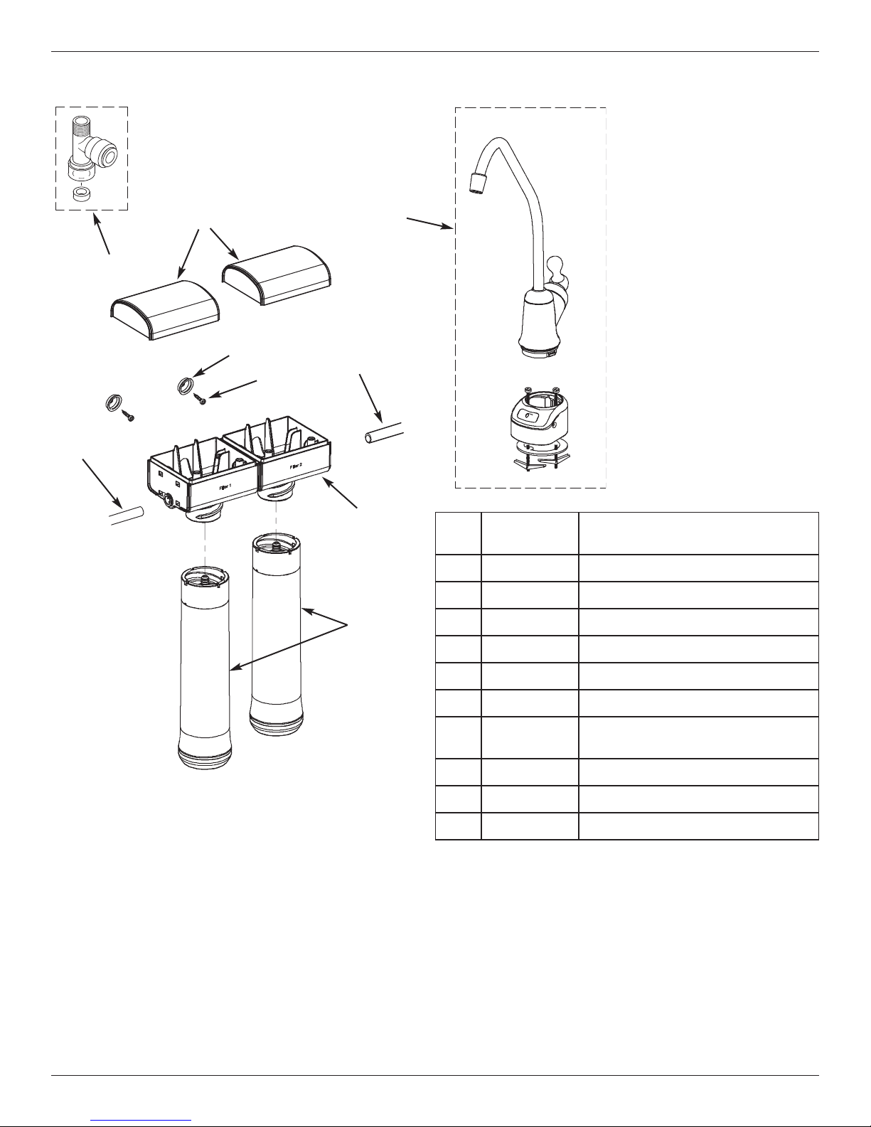
in this owner’s manual for further instructions on filter cartridge replacement, system installation, operating procedures,
and warranty. The maintenance instructions must be followed for the product to perform as indicated below.
General Information
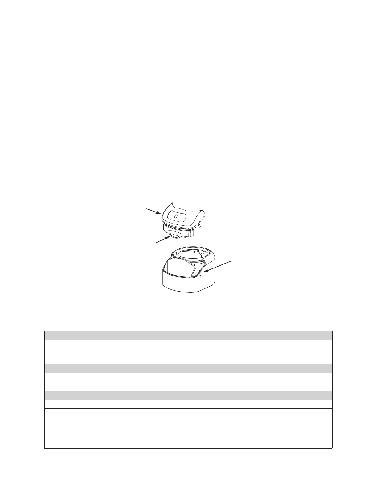
This filter improves the taste and odor and reduces
many chemical contaminants in drinking water. The
faucet indicator monitors the length of time the filter has
been installed and will flash amber continuously; indi-
cating the filters and battery need to be replaced.
This system has been tested according to NSF/ANSI 42
and 53 for reduction of the substances listed below.
The concentration of the indicated substances in water
entering the system was reduced to a concentration
less than or equal to the permissible limit for water leav-
ing the system, as specified in NSF/ANSI 42 and 53.
The testing was performed using spiked tap water at a
flow rate of 0.5 gpm (1.9 L/min.), pH of 7.5 ± 0.5, pres-
sure of 60 psig, and temperature of 68 ±5°F.
Installation Requirements
Pressure Range................. 30-100 psig (207-689 kPa)
Temperature Range ........................ 40-100°F (5-38° )
Service Flow Rate ........................ 0.5 gpm (1.9 L/min.)
Service Life ......................... 270 Gallons (1,022 Liters)
Maintenance
artridges should be replaced every 270 gallons or six
months, whichever comes first. Replacement filter
prices will vary. Estimated costs of replacement filter
elements (part number E ODWF) range from $30.00 to
$50.00 per filter element.
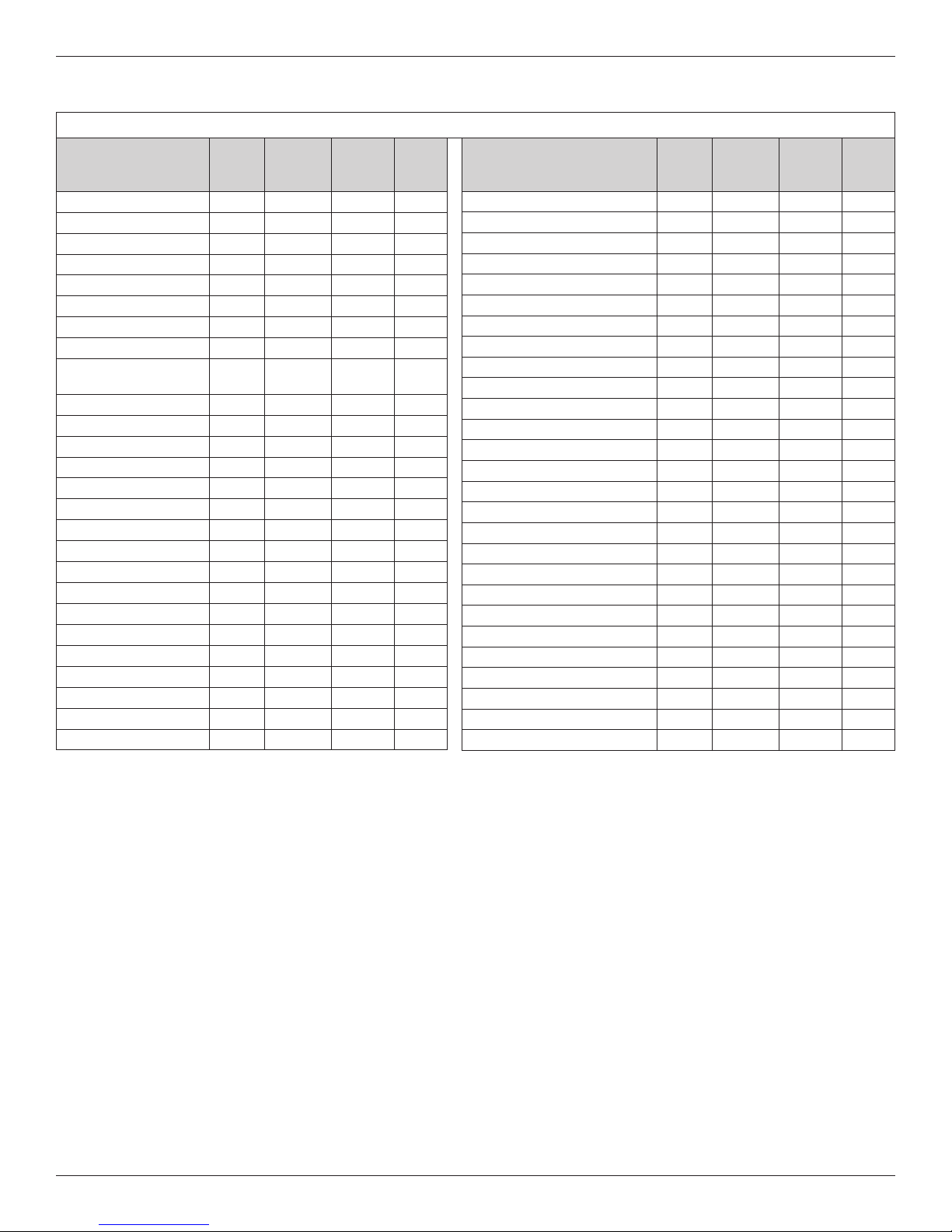
PERF RMANCE CLAIMS
Contaminant
NSF Required
Influent Level
(mg/L)2
NSF Max. Per -
missible Eff.
Level (mg/L)2
Average
Influent Level
(mg/L)2
Avg. / Max.
Effluent
(mg/L)2
Avg. / Min.
Percent
Reduction
EPA MCL1
(mg/L)2
yst ≥50,000
particles / mL4,5 99.95%393,000
particles / mL4<1 / <4
particles / mL499.99 / 99.99 None7
Lead @ pH 6.5 0.15 ±10% 0.010 0.152 0.001 / 0.001 98.8 / 93.1 0.015
Lead @ pH 8.5 0.15 ±10% 0.010 0.150 0.001 / 0.001 99.3 / 99.3 0.015
Methyl tert-Butyl Ether (MTBE) 0.015 ±20% 0.005 0.01467 0.0005 / 0.0005 96.2 / 96.2 None6
Substance
hlorine Taste & Odor 2.0 ±10% 50%32.0 0.05 / 0.08 97.5 / 96.5 None6
V C Reduction7
hloroform 0.30 ±10% 95%30.320 0.0005 / 0.0005 99.8 / 99.8 0.080
1Environmental Protection Agency Maximum ontaminant Level, as required under the Safe Drinking Water Act.
2Milligrams per Liter, which is equivalent to parts per million (PPM).
3NSF minimum percent reduction requirement. Acceptance level for this substance is based on percent reduction, rather than
maximum effluent concentration.
4yst reported in particles per milliliter.
5Microspheres was used as a surrogate.
6The EPA has not determined an M L for this chemical.
7hloroform was used as a surrogate for the reduction of chemicals specified in the Organic hemicals Reduced by hloroform
Surrogate Testing table.
System tested and certified by NSF International against
NSF/ANSI Standard 42 for the reduction of chlorine taste and odor,
and Standard 53 for the reduction of cyst, lead, MTBE and VO s.

12
Performance Data
1Influent challenge levels are average influent concentrations determined in surrogate qualification testing.
2Environmental Protection Agency Maximum ontaminant Level, as required under the Safe Drinking Water Act.
3Micrograms per Liter, which is equivalent to parts per billion (PPB).
4Maximum product water level was not observed, but was set at the detection limit of analysis.
5Maximum product water level is set at a value determined in surrogate qualification testing.
6hemical reduction percent and maximum product water level calculated at chloroform 95% breakthrough point, as determined in sur-
rogate qualification testing.
7The surrogate test results for Heptachlor Epoxide demonstrated a 98% reduction. These data were used to calculate an upper occur-
rence concentration, which would produce a maximum product water level at the M L.
Contaminant
Avg.1
Influent
(µg/L)
3
Maximum
Effluent
(µg/L)
3
Percent
Removal
EPA
MCL2
(µg/L
)3
Alachlor 50 1.04>98 2.0
Atrazine 100 3.04>97 3.0
Benzene 81 1.0499 5.0
arbofuran 190 1.04>99 40
arbon Tetrachloride 78 1.8598 5.0
hlorobenzene 77 1.0499 100
hloropicrin 15 0.2599 NA
2,4-D 110 1.7598 70
Dibromochloropropane
(DB P) 52 0.024>99 0.2
o-Dichlorobenzene 80 1.0499 600
p-Dichlorobenzene 40 1.0498 75
1,2-Dichloroethane 88 4.869565.0
1,1-Dichloroethylene 83 1.0499 7.0
cis-1,2-Dichloroethylene
170 0.54>99 70
trans-1,2-Dichloroethylene
86 1.0499 100
1-2-Dichloropropane 80 1.0499 5.0
cis-1,3-Dichloropropylene
79 1.0499 NA
Dinoseb 170 0.2599 7.0
Endrin 53 0.59599 2.0
Ethylbenzene 88 1.0499 700
Ethylene Dibromide (EDB)
44 0.024>99 0.05
Haloacetonitriles (HAN):
NA
Bromochloroacetonitrile
22 0.5598 NA
Dibromoacetonitrile 24 0.6598 NA
Dichloroacetonitrile 9.6 0.2598 NA
Trichloroacetonitrile 15 0.3598 NA
Contaminant
Avg.1
Influent
(µg/L)
3
Maximum
Effluent
(µg/L)
3
Percent
Removal
EPA
MCL2
(µg/L
)3
Haloketones (HK): NA
1,1-Dichloro-2-Propanone 7.2 0.1599 NA
1,1,1-Trichloro-2-Propanone 8.260.3596 NA
Heptachlor 25 0.014>99 0.4
Heptachlor Epoxide 10.770.2798 0.2
Hexachlorobutadiene 44 1.0498 NA
Hexachlorocyclopentadinene 60 0.0024>99 50
Lindane 55 0.014>99 0.2
Methoxychlor 50 0.14>99 40
Pentachlorophenol 96 1.0499 1.0
Simazine 120 4.0497 4.0
Styrene 150 0.54>99 100
1,1,2,2-Tetrachloroethane 81 1.0499 NA
Tetrachloroethylene 81 1.0499 5.0
Toluene 78 1.0499 1,000
2,4,5-TP (silvex) 270 1.6499 50
Tribromoacetic acid 42 1.0498 NA
1,2,4-Trichlorobenzene 160 0.54>99 70
1,1,1-Trichloroethane 84 4.6595 200
1,1,2-Trichloroethane 150 0.54>99 5.0
Trichloroethylene 180 1.04>99 5.0
Trihalomethanes (includes): 300 15 95 80
hloroform (surrogate chemical)
Bromoform
Bromodichloromethane
hlorodibromomethane
Xylenes (total) 70 1.0499
10,000
RGANIC CHEMICALS REDUCED BY CHL R F RM SURR GATE TESTING
F R I WA USE NLY
All sales in Iowa require the following signature before consummation of sale. These signatures must be retained by
seller/renter for 2 years minimum.
Buyer/Renter __________________________________________________________ Date _________________
Seller ________________________________________________________________ Date _________________
Seller’s Address _______________________________________________________________________________
Seller’s Phone No. _____________________________________________________________________________
Product: EcoPure Model EC P20 Drinking Water Filter
– – – – – – – – – – – – – – – – – – – – – – – – –
"
Table of contents
Other Eco Pure Water Filtration System manuals

Eco Pure
Eco Pure ECOP30 User manual

Eco Pure
Eco Pure EP-ASF1 User manual

Eco Pure
Eco Pure EPWPFF User manual

Eco Pure
Eco Pure EPWHE User manual

Eco Pure
Eco Pure EPWUFF User manual

Eco Pure
Eco Pure EP 6225 User manual

Eco Pure
Eco Pure EP-RO25 User manual

Eco Pure
Eco Pure ECOP30 User manual

Eco Pure
Eco Pure EP-ASF15 User manual

Eco Pure
Eco Pure EPWHCW User manual
Popular Water Filtration System manuals by other brands

CAB
CAB MAESTRO 3E Instructions for use and service

CSI
CSI Signature 2 Nitro Pro Series Installation & operation manual

WilTec
WilTec HW-602B user manual

Pentair
Pentair DELTA ENVIRONMENTAL ECODRIP Series manual

Kohler
Kohler Aquifer 22156-NA installation guide

Perrin & Rowe
Perrin & Rowe UKIT1570LS installation instructions