Eco Pure EP-ASF15 User manual
I stallatio a d Operatio Ma ual
How to install, operate
and maintain your
Automatic Sediment Filter
Manufactured and warranted by
Ecodyne Water Systems
1890 Woodlane Drive
Woodbury, MN 55125
If you have any questions or concerns when
installing, operating or maintaining your Auto-
matic Sediment Filter, call our toll free number:
1-800-693-1138
Monday- Friday, 7 AM - 6 PM CST or visit
www.ecopure.com (U.S.A.)
www.ecopure.ca (Canada)
When you call, please be prepared to provide the
model, date code and serial number of your product,
found on the rating decal, located inside the cover.
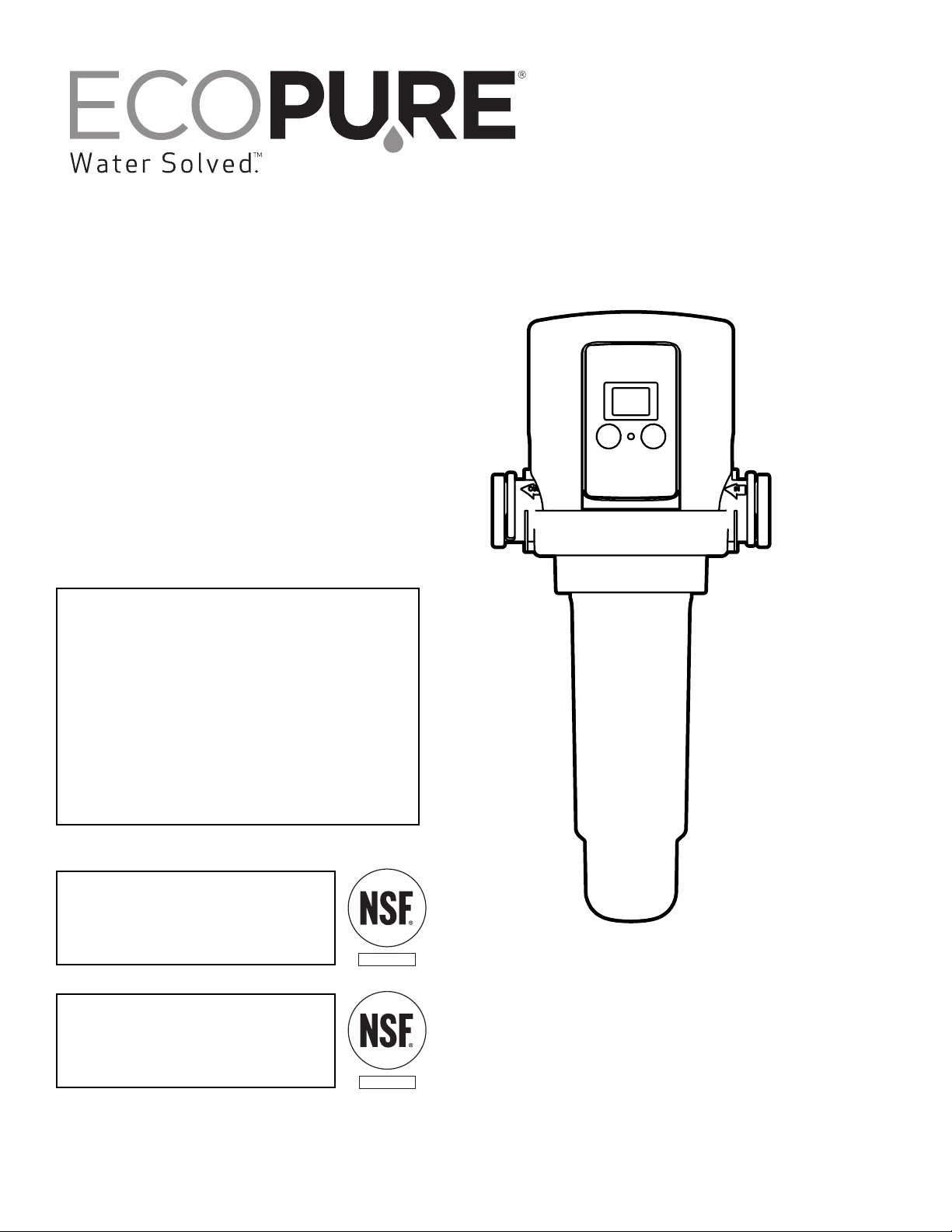
EP-ASF15 is tested and certified
by NSF International against
NSF/ANSI Standard 42 for structural
integrity and materials safety only.
Model EP-ASF15
with filter screen
COMPONENT
Filter screen is tested and
certified by NSF International against
NSF/ANSI Standard 42
for materials safety only.
COMPONENT
201-8402976 (Rev. 00 2/5/15)

2
Table of Co te ts
Before You Start
=Read this entire manual before installing and using your Automatic Sediment Filter. Then, obtain all the materials
and tools you will need to make the installation. Follow all steps exactly and in order to correctly install.
=The Automatic Sediment Filter must only be installed vertically, with the head up and the sump down. It will not
operate properly if installed horizontally or at an angle.
=Check local plumbing, electrical and sanitation codes. You must follow their guides as you install the system.
=Use only lead-free solder and flux for all sweat-solder connections, as required by federal codes.
=Maximum operating pressure: 100 psi.
=Maximum operating temperature: 120 °F.
=Avoid installing in direct sunlight. Excessive sun heat may cause distortion or other damage to non-metallic parts.
=For cold water use only. Do not install on a hot water line.
=Do not use this system to treat water that is microbiologically unsafe or of unknown quality without adequate dis-
infection before or after the system.
=eep solvents and sprays away from the clear sump housing material. Surface cracking and failure can result.
European Directive 2002/96/EC requires all electrical and electronic equipment to be disposed of accord-
ing to Waste Electrical and Electronic Equipment (WEEE) requirements. This directive or similar laws
are in place nationally and can vary from region to region. Please refer to your state and local laws for
proper disposal of this equipment.
In the state of Massachusetts: The Commonwealth of Massachusetts plumbing code 248-CMR shall
be adhered to. A licensed plumber shall be used for this installation.
Before You Start . . . . . . . . . . . . . . . . . . . . . . . . . . . . . . . . . . . . . . . . . . . . . . . . . . . . . . . . . . . . . . . . . . . . . . . . . . . . 2
Warranty . . . . . . . . . . . . . . . . . . . . . . . . . . . . . . . . . . . . . . . . . . . . . . . . . . . . . . . . . . . . . . . . . . . . . . . . . . . . . . . . . . 3
Unpacking §Dimensions . . . . . . . . . . . . . . . . . . . . . . . . . . . . . . . . . . . . . . . . . . . . . . . . . . . . . . . . . . . . . . . . . . . . . 4
How the Automatic Sediment Filter Works . . . . . . . . . . . . . . . . . . . . . . . . . . . . . . . . . . . . . . . . . . . . . . . . . . . . . . . . 5
Specifications . . . . . . . . . . . . . . . . . . . . . . . . . . . . . . . . . . . . . . . . . . . . . . . . . . . . . . . . . . . . . . . . . . . . . . . . . . . . . . 5
Planning the Installation . . . . . . . . . . . . . . . . . . . . . . . . . . . . . . . . . . . . . . . . . . . . . . . . . . . . . . . . . . . . . . . . . . . . . 5-6
Installation Location . . . . . . . . . . . . . . . . . . . . . . . . . . . . . . . . . . . . . . . . . . . . . . . . . . . . . . . . . . . . . . . . . . . . . . 5
Always Install the Filter Upright §Reversing the Faceplate §Mounting Bracket . . . . . . . . . . . . . . . . . . . . . . 6
Installation Requirements . . . . . . . . . . . . . . . . . . . . . . . . . . . . . . . . . . . . . . . . . . . . . . . . . . . . . . . . . . . . . . . . . . . . . 7
Air Gap Requirements . . . . . . . . . . . . . . . . . . . . . . . . . . . . . . . . . . . . . . . . . . . . . . . . . . . . . . . . . . . . . . . . . . . . 7
Valve Drain Requirements . . . . . . . . . . . . . . . . . . . . . . . . . . . . . . . . . . . . . . . . . . . . . . . . . . . . . . . . . . . . . . . . . 7
Grounding Information . . . . . . . . . . . . . . . . . . . . . . . . . . . . . . . . . . . . . . . . . . . . . . . . . . . . . . . . . . . . . . . . . . . . 7
Installation Instructions . . . . . . . . . . . . . . . . . . . . . . . . . . . . . . . . . . . . . . . . . . . . . . . . . . . . . . . . . . . . . . . . . . . . . . 8-9
Attach the Adaptors and Clips to the Filter §Connect the Water Supply Lines . . . . . . . . . . . . . . . . . . . . . . . . 8
Install the Drain Hose §Check For Leaks . . . . . . . . . . . . . . . . . . . . . . . . . . . . . . . . . . . . . . . . . . . . . . . . . . . . 8
Install Battery §Optional AC Adaptor . . . . . . . . . . . . . . . . . . . . . . . . . . . . . . . . . . . . . . . . . . . . . . . . . . . . . . . . 9
Programming the Electronic Controller . . . . . . . . . . . . . . . . . . . . . . . . . . . . . . . . . . . . . . . . . . . . . . . . . . . . . . . 10-11
Power Up §Manually Start a Sediment Flush . . . . . . . . . . . . . . . . . . . . . . . . . . . . . . . . . . . . . . . . . . . . . . . . 10
Normal Operation §LCD Backlight . . . . . . . . . . . . . . . . . . . . . . . . . . . . . . . . . . . . . . . . . . . . . . . . . . . . . . . . 10
Setting Number of Days Between Automatic Sediment Flushes . . . . . . . . . . . . . . . . . . . . . . . . . . . . . . . . . . . 11
Time of Day When Flush Occurs . . . . . . . . . . . . . . . . . . . . . . . . . . . . . . . . . . . . . . . . . . . . . . . . . . . . . . . . . . . 11
Low Battery Indication §Battery Replacement . . . . . . . . . . . . . . . . . . . . . . . . . . . . . . . . . . . . . . . . . . . . . . . . 11
Routine Maintenance . . . . . . . . . . . . . . . . . . . . . . . . . . . . . . . . . . . . . . . . . . . . . . . . . . . . . . . . . . . . . . . . . . . . . . . 12
Cleaning the Filter Screen . . . . . . . . . . . . . . . . . . . . . . . . . . . . . . . . . . . . . . . . . . . . . . . . . . . . . . . . . . . . . . . . 12
Troubleshooting Guide . . . . . . . . . . . . . . . . . . . . . . . . . . . . . . . . . . . . . . . . . . . . . . . . . . . . . . . . . . . . . . . . . . . . . . 13
Disassembly of Solenoid §Disassembly of Valve . . . . . . . . . . . . . . . . . . . . . . . . . . . . . . . . . . . . . . . . . . . . . 13
Repair Parts . . . . . . . . . . . . . . . . . . . . . . . . . . . . . . . . . . . . . . . . . . . . . . . . . . . . . . . . . . . . . . . . . . . . . . . . . . . . . . 14
Questions? Call Toll Free 1-800-693-1138, Monday - Friday, 7 am - 6 pm CST.

3
Warra ty
O E YEAR LIMITED WARRA TY O AUTOMATIC SEDIME T FILTER
Warrantor: Ecodyne Water Systems, 1890 Woodlane Drive, Woodbury, M 55125
Warrantor guarantees, to the original owner, that the Automatic Sediment Filter, when installed and main-
tained in accordance with the instructions, will be free from defects in materials and workmanship for a
period of one (1) year from the date of purchase. If, within the first year, a part proves, after inspection, to
be defective, Warrantor will, at its sole option, either replace or repair the part without charge except instal-
lation charges. Labor and shipping costs to maintain the equipment are not part of the warranty.
TO OBTAIN WARRANTY PARTS, SIMPLY CALL 1-800-693-1138, Monday - Friday, 7 am - 6 pm CST, for
assistance. This warranty applies only while this product is in use in the United States or Canada.
General Provisions
The above warranties are effective provided the Automatic Sediment Filter is operated at water pressures
not exceeding 100 psi, and at water temperatures not exceeding 120°F; provided further that the
Automatic Sediment Filter is not subject to abuse, misuse, alteration, neglect, freezing, accident or negli-
gence; and provided further that the Automatic Sediment Filter is not damaged as the result of any unusu-
al force of nature such as, but not limited to, flood, hurricane, tornado or earthquake.
Warrantor is excused if failure to perform its warranty obligations is the result of strikes, government regu-
lation, materials shortages, or other circumstances beyond its control.
*THERE ARE O WARRA TIES O THE AUTOMATIC SEDIME T FILTER BEYO D THOSE SPECIFI-
CALLY DESCRIBED ABOVE. ALL IMPLIED WARRA TIES, I CLUDI G A Y IMPLIED WARRA TY
OF MERCHA TABILITY OR OF FIT ESS FOR A PARTICULAR PURPOSE, ARE DISCLAIMED TO
THE EXTE T THEY MIGHT EXTE D BEYO D THE ABOVE PERIODS. THE SOLE OBLIGATIO OF
WARRA TOR U DER THESE WARRA TIES IS TO REPLACE OR REPAIR THE COMPO E T OR
PART WHICH PROVES TO BE DEFECTIVE WITHI THE SPECIFIED TIME PERIOD, A D WARRA -
TOR IS OT LIABLE FOR CO SEQUE TIAL OR I CIDE TAL DAMAGES. O WARRA TOR DEAL-
ER, AGE T, REPRESE TATIVE, OR OTHER PERSO IS AUTHORIZED TO EXTE D OR EXPA D
THE WARRA TIES EXPRESSLY DESCRIBED ABOVE.
Some states do not allow limitations on how long an implied warranty lasts or exclusions or limitations of
incidental or consequential damage, so the limitations and exclusions in this warranty may not apply to
you. This warranty gives you specific legal rights, and you may have other rights which vary from state to
state. This warranty applies to consumer-owned installations only.
4
U packi g
Packing List
Filter Assembly
Dime sio s
5-1/4 in.
15 in.
4-1/8 in.
10 in.
FIG. 2
Mounting Bracket 10 ft. Drain Hose
Installation Adaptors
FIG. 1
Clips
10 in.
15 in.
4-1/8 in.5-1/4 in.
9V Battery
Hose Clamp
I SPECT SHIPME T
The Automatic Sediment Filter is shipped complete in
one carton. Remove all items from the shipping carton
and check against the packing list below. Note any
items lost or damaged in shipment. If problems exist,
call our toll free number: 1-800-693-1138, Monday -
Friday, 7 AM - 6 PM CST
Inlet & Outlet
Adaptors
1” NPT threaded
5
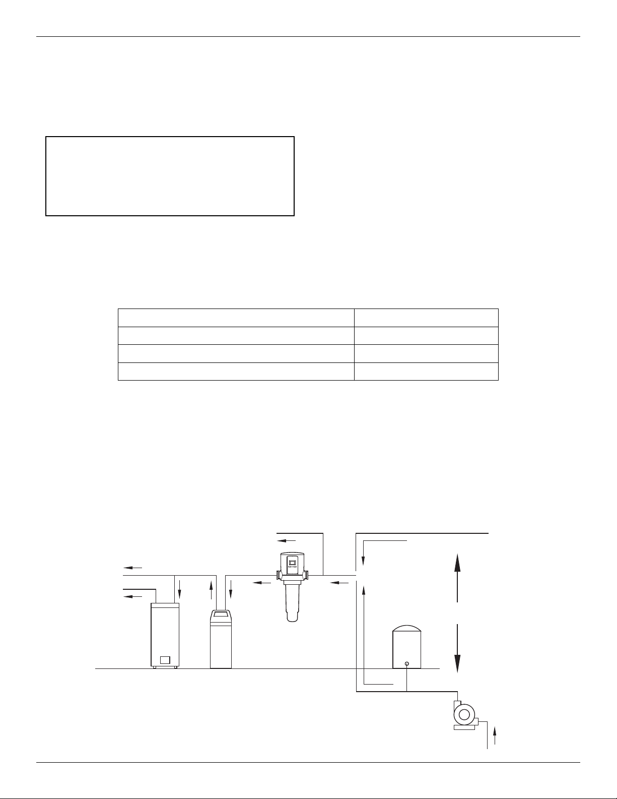
How the Automatic Sedime t Filter Works
Specificatio s
I STALLATIO LOCATIO
To filter sediments from all household water, install the
Automatic Sediment Filter on the household’s main
incoming water pipe. The Automatic Sediment Filter
Pressure
Tank
City Water Supply
Well Water Supply
Well
Pump
OR
Automatic
Sediment
Filter
Untreated Water to
Outside Faucets
Cold Water
to House
should be installed upstream from the water softener
(if any), the water heater and all inside faucets. See
diagram below.
FIG. 3
Water
Softener
Water
Heater
Hot Water
to House
Pla i g the I stallatio
Service Flow Rate 35 gpm (132 lpm)
Water Pressure Limits (minimum / maximum) 30 - 100 psi (207 - 689 kPa)
Water Temperature Limits (minimum / maximum) 40 - 120 °F (5 - 49 °C)
Inlet - Outlet Adaptors 1” NPT male threaded
The EcoPure Automatic Sediment Filter is designed to
be plumbed into a home’s incoming water supply pipe,
where it will capture particles of sediment from the
water and periodically flush them down the drain.
The unit has an electronic control that counts down the
days until the next automatic flush of collected sedi-
ment particles. The number of days is programmable.
The electronic controller runs on a 9 volt battery. The
controller will indicate when the battery needs to be
replaced. An optional AC power adaptor (P/N
7302835) may also be purchased to eliminate the
need for batteries.
Three sizes of filter mesh are available. A 60 micron fil-
ter is included with the ASF unit, and optional 100 or
150 micron filters can also be purchased (see spare
parts list at the end of this manual).
OTE: This product is designed to reduce sand,
grit, debris, pipe scale and other loose matter. On
water supplies that contain sticky sediment includ-
ing mud, silt and clay, you may have to remove
the sump and clean the screen periodically.
10 in.
min.
6 in.
min.
IN
OUT
House W
Supply
Sump
Pointed
Straight
Down
6
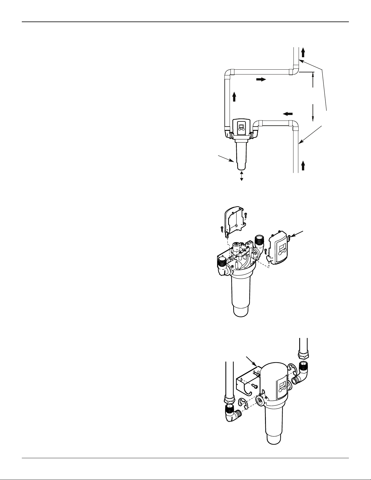
Pla i g the I stallatio (co ti ued)
FIG. 4
FIG. 6
FIG. 5
10 in.
min.
B
D
E
Remove 2
screws and
turn faceplate
around, if
necessary
ALWAYS I STALL THE FILTER UPRIGHT
To operate properly, the Automatic Sediment Filter
must be installed with the sump pointed straight down.
When possible, install the filter on a horizontal section
of the household’s main incoming water pipe. If the
available incoming main house water pipe runs verti-
cally where you want to install the filter, buy 90° pipe
elbows and plumb a detour, as shown in Figure 4.
Allow enough space under the filter (6” minimum) to
remove the sump (to clean or replace the filter screen).
Allow enough space above the filter to remove the top
cover (to change batteries, etc.), as shown in Figure 4.
REVERSI G THE FACEPLATE / DISPLAY
The Automatic Sediment Filter must be installed with
the water flowing into the side of the filter marked I .
Remove the unit’s top cover and observe the IN and
OUT markings. Depending on the direction of water
flow and the viewing angle, the faceplate may need to
be reversed (turned around to face the opposite direc-
tion) so that it does not end up against a wall or other
obstruction. This can be done either before or after
the filter is installed on the plumbing:
1. Remove the top cover from the ASF by sliding it
upward.
2. With a phillips screwdriver, remove the 2 screws
holding the faceplate assembly to the filter head
(See Figure 5).
3. Lift the faceplate assembly up and turn it around
180°, taking care not to pull on the wires between
the electronic control board and the valve solenoid.
4. Lower the faceplate assembly into place on the
opposite side of the head and reinstall the 2 screws.
5. Slide the top cover back onto the ASF and push it
down to snap into place.
MOU TI G BRACKET
A metal bracket is included with the Automatic
Sediment Filter to support the assembled filter and
plumbing when necessary. It may be mounted to a
wall or wall framing member with 2 screws (included),
as shown in Figure 6.
Mounting
Bracket
House
Water
Supply
Pipe
I
OUT
6 in.
min.
Sump
Pointed
Straight
Down

Aim end of drain
hose toward center
of drain. Tie or wire
tubing in place.
Drain grate
with 1 in. dia.
hole in center
1-1/2 in.
air gap
To drain point other
than floor drain.
Support tubing
place as needed.
Drain
Fitting
Hose
Clamp
Valve Drain
Hose
IMPORTANT:
To prevent drain hose from
detaching from system during a flush
do not kink, crush or obstruct the hose.
IMPORTANT:
Flow
at higher pressure. Be sure to secure
both ends of drain hose properly and test.
7
I stallatio Requireme ts
PLUMBI G CODES
All plumbing must be completed in accordance with
national, state and local plumbing codes.
VALVE DRAI REQUIREME TS
Using the flexible drain hose (included), measure and
cut to the length needed.
=Avoid drain hose runs longer than 10 feet. Make
the valve drain line as short and direct as possible.
=If possible, avoid elevating the drain hose. This
could reduce the effectiveness of the flush cycle,
especially in a low pressure application.
=The drain must be capable of handling a flow of 5
to 10 gallons per minute, depending on the home’s
water pressure.
=The drain must be capable of handling the sediment
being flushed from the filter.
1-1/2”
air gap
FIG. 8
LAU DRY TUB STA DPIPE
1-1/2”
air gap
FLOOR DRAI
In the state of Massachusetts: The Commonwealth
of Massachusetts plumbing code 248-CMR shall
be adhered to. A licensed plumber shall be used
for this installation.
AIR GAP REQUIREME TS
A drain is needed for sediment flush discharge water.
A floor drain, close to the Automatic Sediment Filter, is
preferred. A laundry tub, standpipe, etc. are other
drain options. The valve drain hose must be secured
in place, since drain water will be spraying from the
end of the hose at a high rate during flush cycles.
Leave an air gap of 1-1/2” between the end of the
hose and the drain. This gap is needed to prevent
backflow of sewer water into the Automatic Sediment
Filter. Do not put the end of the drain hose into the
drain.
Clamp
(2 - not
included)
Ground Wire
(not included)
FIG. 7
GROU DI G I FORMATIO
(for Installations on Metal Pipe)
The house main incoming water pipe is often
used to ground electrical outlets in the home.
Grounding protects you from electrical shock.
Installing the Automatic Sediment Filter may break
this ground. To restore it, buy and install a #4
copper wire across the filter, tightly clamped at
both ends, as shown below.
IMPORTA T:
Flow rate to drain can
exceed 9 gpm at high-
er pressure. Be sure
to secure drain hose
properly and test.
Clamp
(2 -not
included)
Ground Wire
(not included)
CO ECTI G VALVE TO DRAI
1-1/2 in.
air gap
Drain grate
with 1 in. dia.
hole in center
Valve Drain
Hose
Drain
Fitting
Hose
Clamp
Aim end of drain
hose toward center
of drain. Tie or wire
tubing in place.
To drain point other
than floor drain.
Support tubing in
place as needed.
8
I stallatio
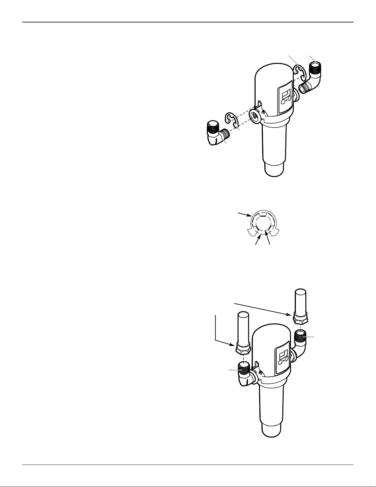
A. ATTACH THE ADAPTORS A D CLIPS
TO THE FILTER
1. Insert the adaptors into the holes on each side of
the filter head (See Figure 9).
2. Secure in place with clips. Ensure all three tabs on
the clips go through the matching holes and are fully
in the channels on the adaptor (See Figure 10).
B. CO ECT THE WATER SUPPLY LI ES
IMPORTA T: Do not solder the metal plumbing while
attached to plastic installation adaptors.
Solder heat will damage the adaptors.
1. Seal the inlet and outlet threads on the filter adap-
tors (See Figure 11) with several wraps of sealant
tape.
2. Connect the water supply lines to the inlet and out-
let using 1 in. female NPT threaded adaptors (not
included). Use caution to avoid cross-threading the
adaptors.
C. I STALL THE DRAI HOSE
Do the following before turning the water supply back
on:
1. Measure, cut to needed length and connect the 3/8
in. drain line (provided) to the Automatic Sediment
Filter’s valve drain fitting (See Figure 8 on Page 7).
Use a hose clamp to hold hose in place.
2. Run the drain hose or copper tubing to the floor
drain. Secure drain hose. This will prevent the
drain line from “whipping'' during sediment flush
cycles. See “Air Gap Requirements" section.
D. CHECK FOR LEAKS
1. With the installation steps completed, fully open the
home’s main water supply valve.
2. Check for leaks at all the plumbing connections you
made.
3. Make sure the electronics are completely dry before
powering the unit up (as described in the next sec-
tion).
E
D
E
D
FIG. 9
FIG. 10
CORRECT ASSEMBLY
Clip
Outside diameter
of clip channel
on Adaptor
Outside diameter
of Filtration
System Head
AdaptorClip
Clip
Adaptor
1
2
FIG. 11
OUTLET
Use thread
sealing tape
I LET
Use thread
sealing tape
1 in. female
NPT adaptors
(not included)
9
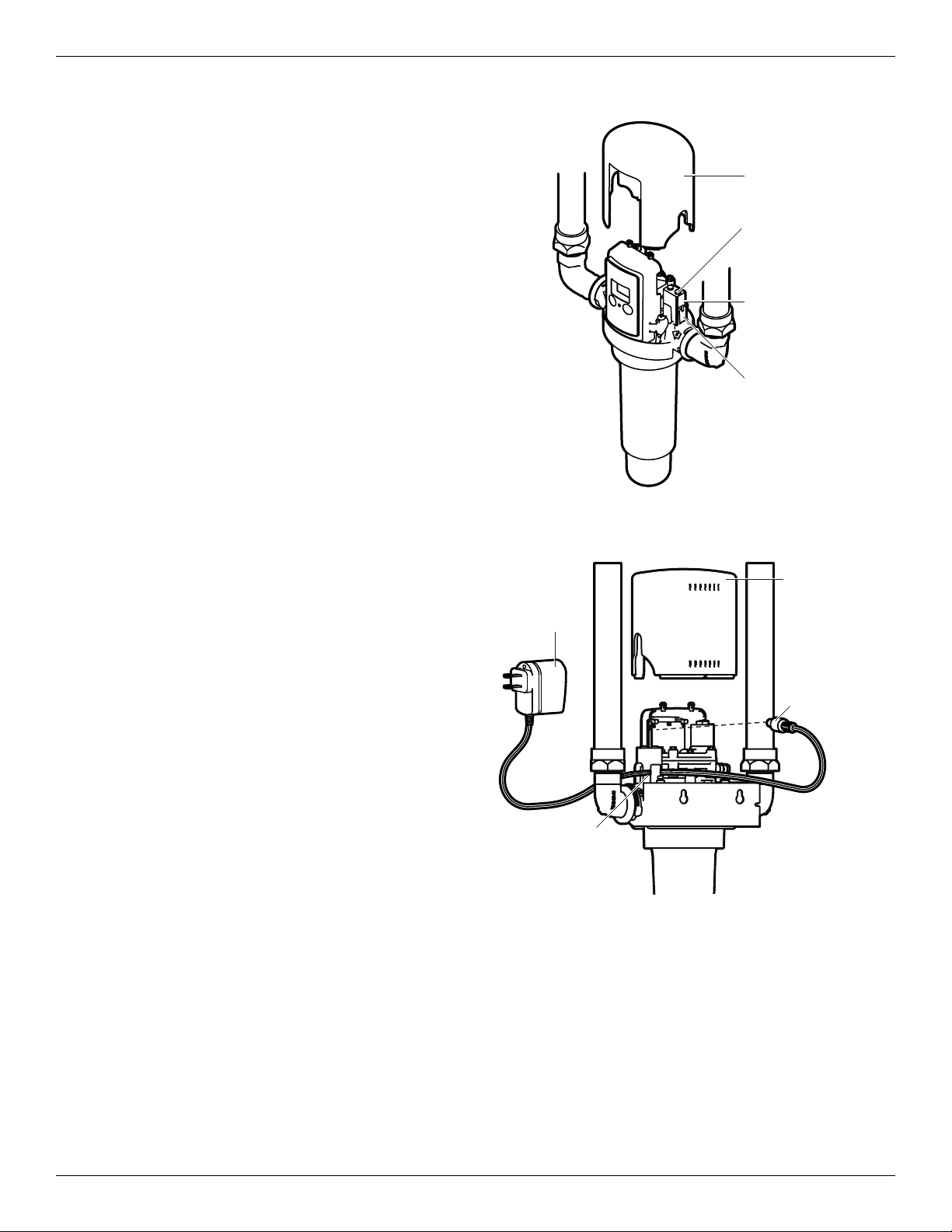
I stallatio (co ti ued)
Top Cover
Plug into
Connector on
Electronic
Control Board
Feed Wire
through Slot
Optional
AC Adaptor
E. I STALL THE BATTERY
1. Take the included 9V battery out of its plastic wrap.
2. Remove the top cover from the ASF by sliding it
upward (See Figure 12).
3. Snap the battery connector onto both terminals of
the 9V battery.
4. Place the connected battery into the clip provided
for it directly above the IN port (See Figure 12).
5. Slide the top cover back onto the ASF and push it
down to snap into place.
F. OPTIO AL AC ADAPTOR (not included)
An optional AC adaptor (P/N 7302835) is available to
supply 9V DC power to the electronic control instead
of using a 9V battery. This adaptor has 5 feet of wire.
One end plugs into a household 120V AC, 60 Hz. out-
let and the other end plugs into the back of the elec-
tronic control board, as shown in Figure 13. See the
Repair Parts List page for ordering information.
IMPORTA T: Do not use any AC adaptor other than
the EcoPure P/N 7302835 with this
Automatic Sediment Filter.
To install the optional AC adaptor:
1. Remove the top cover from the ASF by sliding it
upward (See Figure 13).
2. Remove any previously installed 9V battery from the
ASF (disconnect it from the battery connector and
lift it out of the clip above the IN port).
3. Locate the small round plug on one end of the AC
adaptor cable and insert this into the connector on
back of the electronic control board (See Figure 13).
4. Plug the other end of the AC adaptor into a 120V,
60 Hz household electric socket.
5. Before replacing the cover on the ASF, feed the wire
through the small slot above the IN port of the ASF
(See Figure 13).
6. Slide the top cover back onto the ASF, making sure
not to pinch any wires, and push it down to snap
into place.
Top Cover
9V Battery
Battery Connector
Clip
FIG. 12
FIG. 13
Plug into
Connector on
Electronic
Control Board
Top Cover
Battery Connector
Clip
9V Battery
Top Cover
Feed Wire
through Slot
Optional
AC Adaptor
10
Programmi g the Electro ic Co troller
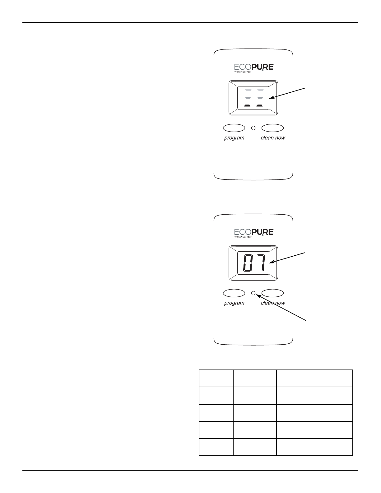
LED color State of LED Shows when...
Green Blinks every
8 sec. Unit is in normal operation
Amber On steadily You are programming
the controller
Red Blinks every
8 sec. Battery is low
None Completely
Off
Battery is dead
or disconnected
POWER UP
When the controller is powered up (by installing the
battery or plugging in the optional AC adaptor), the dis-
play will briefly show the software version (example
“1.0”), then the number of days until the next automatic
sediment flush.
MA UALLY START A SEDIME T FLUSH
After all installation steps have been completed, initiate
a manual sediment flush as follows:
1. Press the CLEAN NOW button and hold it for at
least 2 seconds. When the 2-digit display changes
to show moving dashes (See Figure 14), release the
CLEAN NOW button.
2. Check drain hose to ensure a secure connection.
3. The sediment flush sequence takes about 30 sec-
onds to complete. The flow of water to the drain will
start and stop several times.
4. Once the sediment flush has been completed, the 2-
digit display will change to show the number of days
until the next automatic flush (or if the automatic
flush feature has been turned off it will show “- -”).
The ASF can be manually activated to flush sediment
at any time, regardless of whether or not it is set to
flush automatically.
ORMAL OPERATIO
During normal operation, the LED will momentarily
blink green every 8 seconds and the 2-digit display
(LCD) will show the number of days remaining until the
next automatic sediment flush. Momentarily pressing
the PROGRAM button shows the setting for the num-
ber of days between flushes.
LCD BACKLIGHT
The 2-digit display has a backlight that goes on when-
ever a button is pressed. It goes off again after 10
seconds if no more buttons have been pressed (to
conserve battery life). Momentarily press either the
PROGRAM or CLEAN NOW button to turn on the
backlight.
Moving dashes
indicate sedi-
ment flush is
taking place
FIG. 14
LED (see
Table below)
2-Digit LCD
Display
(when unit is in
normal opera-
tion, shows
number of days
until next auto-
matic sediment
flush)
FIG. 15
11
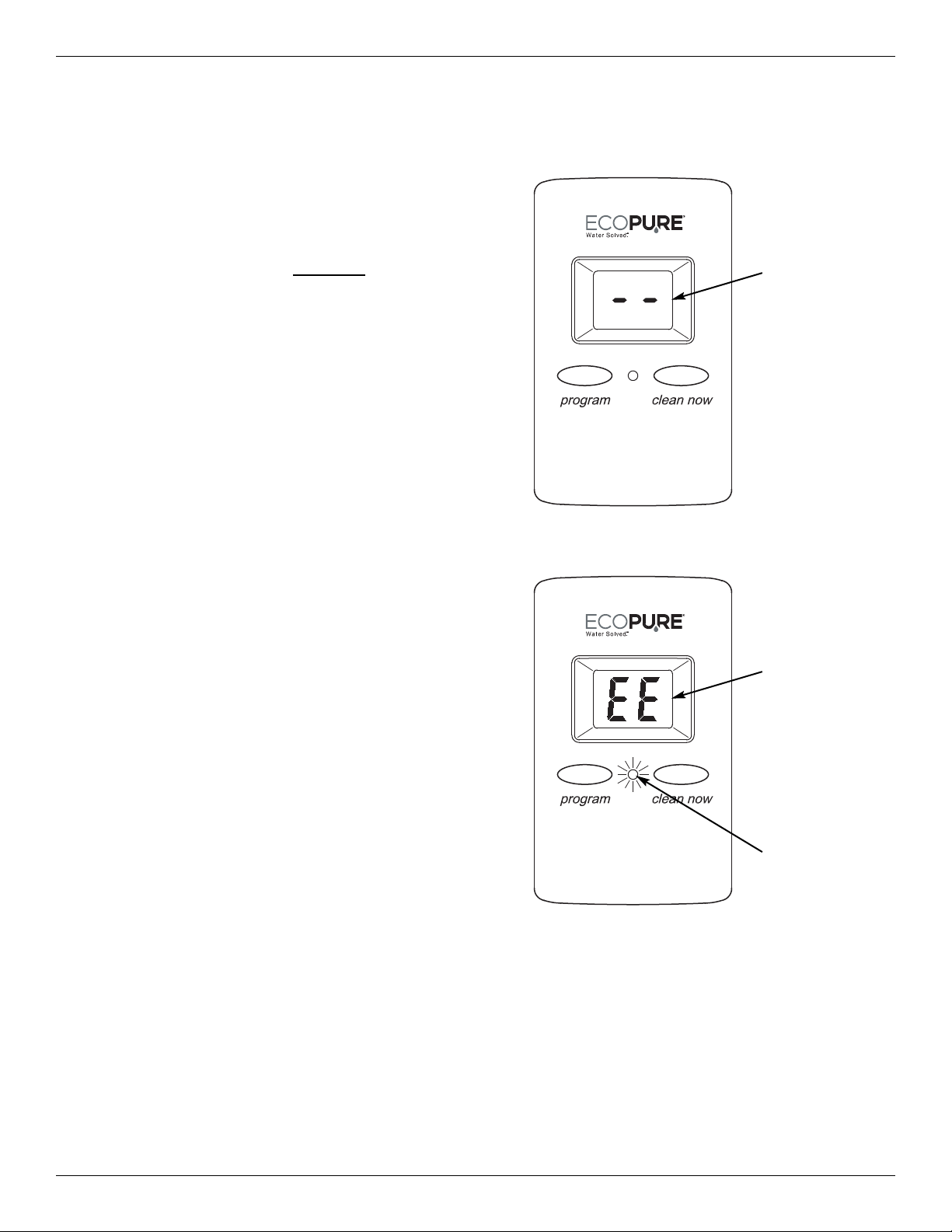
Electro ic Co troller (co ti ued)
LED blinking
red every 8
sec. indicates
battery is low
“E E” in the
display indi-
cates battery
is low
FIG. 17
Two dashes
(not moving)
in the display
indicate auto-
matic flush is
turned off
FIG. 16
3. Take a new 9-volt battery and snap the battery con-
nector onto both terminals.
4. Place the connected battery into the clip provided
for it directly above the IN port (See Figure 12 on
Page 9).
5. Slide the top cover back onto the ASF and push it
down to snap into place.
No reprogramming of the controller is necessary after
battery replacement or a power outage.
The ASF controller is shipped with a default value of 7
days between automatic sediment flushes. To change
the number of days (between 1 and 30) or to turn this
feature off:
1. Press the PROGRAM button and hold it for at least
2 seconds. When the LED turns on steadily with an
amber color, quickly release the PROGRAM button.
2. While the amber LED is on (it turns off after 10 sec-
onds of button inactivity), repeatedly press the PRO-
GRAM button until the desired number of days
shows in the display. Each press increases the
number of days by 1. When the number passes 30,
it returns to zero, indicated by “- -”, and counts up
from 1 again.
3. Setting the number of days to “- -” (zero) turns off
the automatic flush feature.
4. When the desired number of days shows in the dis-
play, wait 10 seconds (press no more buttons) for
the amber LED to go off. The new number of days
is programmed. This new setting will remain after
battery change or power loss.
TIME OF DAY WHE FLUSH OCCURS
The time of day when the automatic sediment flush will
occur is the same time of day as when the most recent
of the following was done:
=The filter was powered up (battery installed or
replaced, optional AC adaptor plugged in).
=The number of days was set
=A manual flush was initiated
If a different time of day is desired for automatic flush,
simply initiate a manual flush (as described on the pre-
vious page) at the desired time of day.
LOW BATTERY I DICATIO
If the LED is blinking red every 8 seconds (and the 2-
digit display shows “E E“), then the battery needs to be
replaced.
BATTERY REPLACEME T
1. Remove the top cover from the ASF by sliding it
upward (See Figure 12 on Page 9).
2. Locate the old battery and unsnap it from the bat-
tery connector. Dispose of (recycle) old battery
properly.
SETTI G THE UMBER OF DAYS BE TWEE
AUTOMATIC SEDIME T FLUSHES
O-Ring
Drain Straw
Filter
Screen
O-Ring
Sump
Head
12
Routi e Mai te a ce
CLEA I G THE FILTER SCREE
It may be necessary to manually clean the filter screen from
time to time. On water supplies that contain sticky sediment
including mud, silt and clay, you may have to remove the
sump and clean the screen frequently. Also, if the ASF has
not been automatically flushing for any reason, such as a
dead battery, a larger amount of sediment than normal may
have accumulated in the sump. In this case it is recom-
mended that the sump and filter be cleaned manually (an
excess amount of sediment could plug the valve).
1. Before shutting off the water supply (as directed in Step
2), run a bucketful or sinkful of water to use for cleaning
the filter screen.
2. Shut off the main house water supply valve upstream from
the Automatic Sediment Filter.
3. Open a cold water faucet in the house (downstream from
the ASF) to depressurize the system. Then close this
faucet again
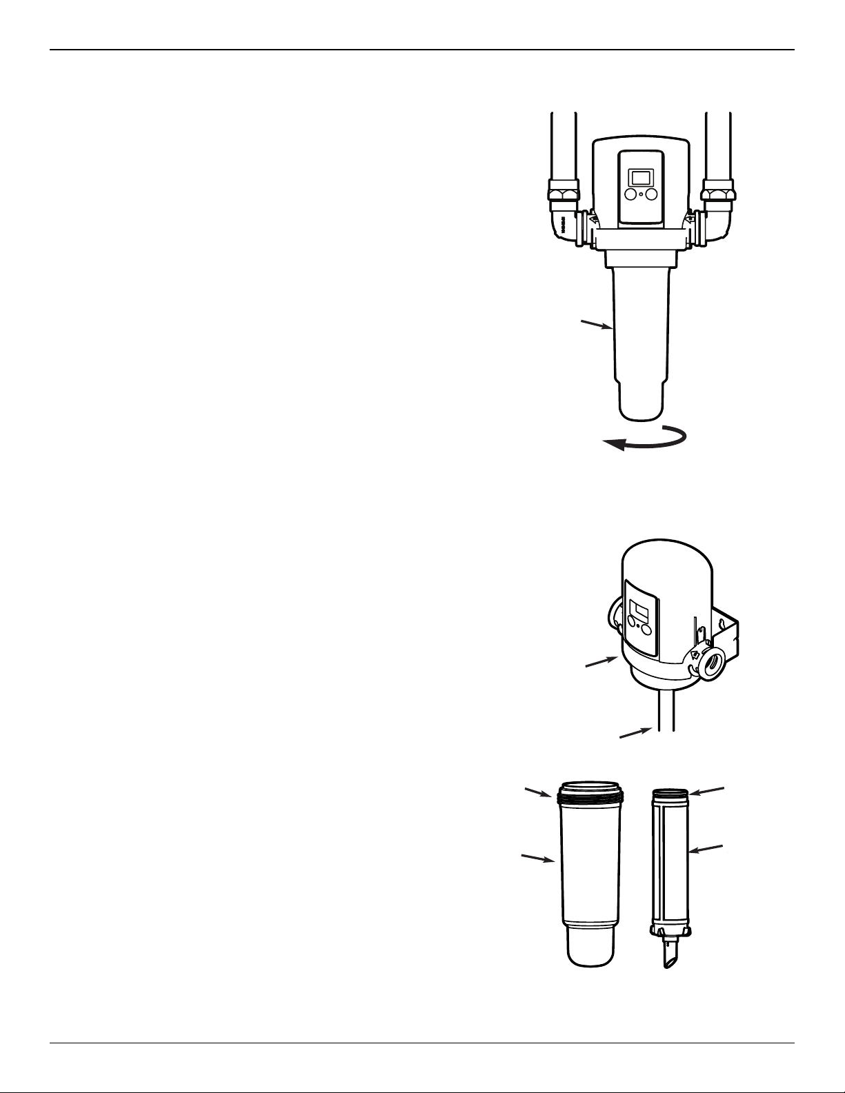
4. Remove the sump by turning it to the left to unscrew it
from the ASF head (See Figure 18). Be prepared for
water to drip out of the ASF head when the sump is
removed.
5. Remove the filter screen assembly by pulling it down out
of the ASF head (See Figure 19).
6. Using the water you saved in Step 1, wash the filter
screen assembly. If necessary, gently scrub the filter
mesh with a soft brush to remove material from the pores.
7. The drain straw may have come out of the ASF head
when the sump and filter screen were removed. If so,
reinsert it into the small hole at the center of the head
assembly (See Figure 19).
8. Make sure the o-ring is in place on the filter screen
assembly (See Figure 19). Make sure that no sediment
particles are on the o-ring or the corresponding sealing
area in the head. Slide the filter screen over the drain
straw and into the corresponding hole at the center of the
ASF head. Push it in to engage the o-ring seal.
9. Make sure the large o-ring is in place on the sump (See
Figure 19). Make sure no sediment particles are on the o-
ring, sump threads or corresponding threads in the ASF
head. Slide the sump over the filter screen and screw it
into the ASF head to seal. Do not overtighten.
10. Open a cold water faucet in the house downstream from
the ASF.
11. Turn the main house water supply back on.
12. Close the faucet that you opened in Step 10 after air has
been expelled from the system and water is flowing
smoothly with no spurting.
13. Check that there is no water leaking from the sump
threads. Tighten sump if necessary.
Turn to the
left to remove
Sump
FIG. 18
FIG. 19
Turn to the
left to remove
(with water shut off)
Sump
Sump
O-Ring
Head
Drain Straw
O-Ring
Filter
Screen

13
Troubleshooti g
PROBLEM CAUSE CORRECTIO
Sediment flush
does not initiate
1. Battery is dead. Replace battery (See “Battery Replacement” on Page 11).
Low or no water
flow through filter
1. Filter is plugged. Manually clean filter screen (See Page 12). May be necessary to reduce
number of days be tween automatic sediment flushes (See Page 11).
Sediment does
not leave sump
during sediment
flush cycle
1. Valve is plugged. Manually clean filter screen (See Page 12). After water has been turned
back on, initiate another clean cycle (hold CLEAN NOW button for 2
sec.). Repeat if necessary. If caused by too great a volume of sediment,
may be necessary to reduce number of days be tween automatic sedi-
ment flushes (See Page 11). If this does not clear plugged valve, it may
be necessary to disassemble valve and clean manually (See
“Disassembly of Valve,” below).
2. Drain hose is plugged. Disconnect drain hose, remove obstruction and reconnect.
3. Insufficient water pressure. Make sure water pressure requirement (30 psi minimum) is met. Shorten
drain line.
4. Misapplication of product. See application information (“How the Automatic Sediment Filter Works”)
on Page 5.
Continuous leak
to drain
1. Solenoid seat is dirty. Initiate several clean cycles. If leak continues, then remove valve sole-
noid and clean seat area (See “Disassembly of Solenoid”, below).
2. Valve is plugged or valve
seat is dirty.
Manually clean filter screen (See Page 12). After water has been turned
back on, initiate another clean cycle (hold CLEAN NOW button for 2
sec.). Repeat if necessary. If caused by too great a volume of sediment,
may be necessary to reduce number of days be tween automatic sedi-
ment flushes (See Page 11). If this does not clear plugged valve, it may
be necessary to disassemble valve and clean manually (See “Dis -
assembly of Valve,” below).
DISASSEMBLY OF SOLE OID
(See Exploded View on Page 14)
If the troubleshooting table, above, indicates that the sole-
noid seat requires cleaning, use the following procedure:
1. Before shutting off the water supply (as directed in Step
2), run a bucketful or sinkful of water to use for cleaning.
2. Shut off the main house water supply valve upstream from
the Automatic Sediment Filter.
3. Open a cold water faucet in the house (downstream from
the ASF) to depressurize the system. Close faucet again.
4. Remove the solenoid ( ey No. 6 on Page 14) by unscrew-
ing it from the top of the valve.
5. Using the water you saved in Step 1, clean the solenoid
seat, plunger and hole.
6. Make sure the o-ring ( ey No. 7) is in place and reinstall
the solenoid, being careful not to cross-thread.
7. Open a cold water faucet downstream from the ASF.
8. Turn the main house water supply back on.
9. Close the faucet that you opened in Step 7 after air has
been expelled from the system.
10. Check that there is no water leaking from the solenoid
thread area. Tighten solenoid if necessary.
DISASSEMBLY OF VALVE
(See Exploded View on Page 14)
If the troubleshooting table, above, indicates that the valve
requires cleaning, use the following procedure:
1. Before shutting off the water supply (as directed in Step
2), run a bucketful or sinkful of water to use for cleaning.
2. Shut off the main house water supply valve upstream from
the Automatic Sediment Filter.
3. Open a cold water faucet in the house (downstream from
the ASF) to depressurize the system. Close faucet again.
4. Remove the six screws ( ey No. 8 on Page 14) from the
top of the valve and lift off the valve cover ( ey No. 9).
5. Using the water you saved in Step 1, clean the diaphragm
ey No. 12) and seat area of valve body ( ey No. 13).
6. Make sure the two small holes in the valve body under the
diaphragm are not plugged.
7. Reassemble the valve, making sure the diaphragm is right
side up (small knob at center points up) and the other
components are properly placed, as shown on Page 14.
8. Open a cold water faucet downstream from the ASF.
9. Turn the main house water supply back on.
10. Close the faucet that you opened in Step 8 after air has
been expelled from the system.
11. Check that there is no water leaking from the valve seal-
ing area. Tighten screws if necessary.
eed help troubleshooting? Call Toll Free 1-800-693-1138, Monday - Friday, 7 am - 6 pm CST.

Repair Parts
1
4
20
6
17
18
21 19
8
9
12
13
15
14
16
11
27
7
10
5
2
26
24
22
23
25
3
ey
No. Part No. Description
1 7298442 Top Cover
2 7295177 Electronic Control Board (PWA)
3 7298434 Faceplate (order decal below)
4 107-8402980 Decal, Faceplate, EcoPure
5 7300346 Screw, 6-19 x 1/2” (2 req.)
6 7301596 Solenoid
7 7301758 O-Ring, Solenoid
8 7300338 Screw, 10-16 x 1-1/4” (6 req.)
9 7298426 Valve Cover
10 7301520 Spring
11 7301685 Retainer, Spring
12 7301512 Diaphragm
13 7298418 Valve Body
14 7300320 O-Ring, Valve (2 req.)
15 7272658 Check Valve
16 1073-27-01 Head Assembly
17 7300312 O-Ring, Sump
18 7298395 Sump
19 7300304 Drain Straw
ey
No. Part No. Description
20
7298808 Filter Screen Assembly,
60 Micron (includes ey No. 21)
7298816 Filter Screen Assembly, 100
Micron (includes ey No. 21) Ù
7298824 Filter Screen Assembly, 150
Micron (includes ey No. 21) Ù
21 7011086 O-Ring, Filter
22 7139999 Drain Hose, 20 ft.
23 0900431 Clamp, Drain Hose
24 1073-27-03 Bracket, Mounting
25 9006053 Screw, 10-16 AB (2 req.)
26 7302835 AC Power Adaptor Ù
27 – Battery, 9 Volt, Standard
28 1042-32-HA Installation Adaptor (2 req.)
29 1042-32-22 Clip (2 req.)
¢201-8402976 Owner’s Manual
¢Not illustrated.
ÙOptional - not included with Automatic Sediment Filter.
29
28
14
To order repair parts call toll free
1-800-693-1138,
Monday - Friday, 7 am - 6 pm CST.
Table of contents
Other Eco Pure Water Filtration System manuals

Eco Pure
Eco Pure EPWPFF User manual

Eco Pure
Eco Pure ECOP30 User manual

Eco Pure
Eco Pure ECOP20 User manual

Eco Pure
Eco Pure EP-RO25 User manual

Eco Pure
Eco Pure ECOP30 User manual

Eco Pure
Eco Pure ECOP20 User manual

Eco Pure
Eco Pure EPWHCW User manual

Eco Pure
Eco Pure EPWUFF User manual

Eco Pure
Eco Pure EP 6225 User manual

Eco Pure
Eco Pure EP-ASF1 User manual


