ECO SPARK eco SPARK 30 User manual

Table of Contents
Magen eco-Spark®Installation manual. © 2012, all rights reserved P a g e | 1
www.magen-ecoenergy.com

Table of Contents
Magen eco-Spark®Installation manual. © 2012, all rights reserved P a g e | 2
TABLE OF CONTENTS
PREFACE ....................................................................................................................................................................... 5
Overview .......................................................................................................................................................................... 5
Safety precautions and regulations.................................................................................................................................. 5
Transport and handling................................................................................................................................................ 6
Lightning protection..................................................................................................................................................... 6
Definitions of terms used in this document ..................................................................................................................... 7
Modules/panels/banks..................................................................................................................................................... 7
Dimensions & specifications......................................................................................................................................... 8
Maximum operation pressure.......................................................................................................................................... 8
Pressure drop ............................................................................................................................................................... 8
Wind and snow load......................................................................................................................................................... 8
DESIGNING YOUR SYSTEM............................................................................................................................................ 9
The solar system layout.................................................................................................................................................... 9
Collector area ................................................................................................................................................................... 9
Proximity to pool .............................................................................................................................................................. 9
Location & Orientation..................................................................................................................................................... 9
Tilt................................................................................................................................................................................... 10
Preparing a schematic diagram ...................................................................................................................................... 10
Sample collector system................................................................................................................................................. 11
Mounting racks............................................................................................................................................................... 12
PARTS AND TOOLS.......................................................................................................................................................13
Fittings and accessories.................................................................................................................................................. 14
Connecting between panels/modules........................................................................................................................ 14
Ends of a bank............................................................................................................................................................ 14
Securing panels to the roof ........................................................................................................................................ 15
eco-SPARK®fittings summary .................................................................................................................................... 15
Pipes and other fittings .................................................................................................................................................. 15
Pipes ........................................................................................................................................................................... 15
Fittings ....................................................................................................................................................................... 15
Other fittings .............................................................................................................................................................. 16
Tools........................................................................................................................................................................... 16
HYDRAULICS ................................................................................................................................................................17
Panel configurations....................................................................................................................................................... 17
Basic plumbing & arrays layouts .................................................................................................................................... 17
Plumbing......................................................................................................................................................................... 18
Water inlet /outlet ..................................................................................................................................................... 18
Pipe diameter ............................................................................................................................................................. 19
Plumbing runs ............................................................................................................................................................ 19
Balanced flow............................................................................................................................................................. 19
Pump power ............................................................................................................................................................... 20
Automatic drainage ................................................................................................................................................... 20
Compensating for lack of automatic drainage........................................................................................................... 20

Table of Contents
Magen eco-Spark®Installation manual. © 2012, all rights reserved Page | 3
INSTALLATION .............................................................................................................................................................21
Connecting panels together ........................................................................................................................................... 21
Connecting across a large obstruction ........................................................................................................................... 24
Fixing panels to a sloping roof........................................................................................................................................ 24
Mounting panels using S roof mounting pads................................................................................................................ 25
Fixing panels to a flat roof .............................................................................................................................................. 27
Pipes connections - CPVC Cementing............................................................................................................................. 28
CPVC cementing ......................................................................................................................................................... 28
Pipes connections - pex welding .................................................................................................................................... 29
PEX welding (using pex2pex Electrofusion couplers).................................................................................................. 29
Pipes connections - ppr welding..................................................................................................................................... 31
CONNECTING TO EXISTING EQUIPMENT......................................................................................................................32
Feed and return lines ..................................................................................................................................................... 32
Connecting to existing filtration system Plumbing guidelines ....................................................................................... 33
Connect with the filtration system ............................................................................................................................. 35
Running feed and return lines to ground level ........................................................................................................... 36
Automatic systems (private & public pools)................................................................................................................... 37
OPERATION .................................................................................................................................................................39
Before letting water into the system ............................................................................................................................. 39
High pressure testing...................................................................................................................................................... 39
Turning the system on (manual systems)....................................................................................................................... 40
Turning the system on (automatic systems) .................................................................................................................. 40
Turning the system off (manual systems) ...................................................................................................................... 40
Turning the system off (automatic systems) .................................................................................................................. 41
MAINTENANCE ............................................................................................................................................................41
Maintenance requirements........................................................................................................................................ 41
TROUBLSHOOTING ......................................................................................................................................................42
DISABLING A DAMAGED RISER TUBE ...........................................................................................................................44
®.........................................................................................................................47
Direct pre-heating .......................................................................................................................................................... 47
Solar hot water storage tank .......................................................................................................................................... 49
SITE EVALUATION SHEET .............................................................................................................................................51
Client contact info ...................................................................................................................................................... 51
Site info ...................................................................................................................................................................... 51
Basic system layout .................................................................................................................................................... 52
............................................................................................................................................53
Standards and certifications.......................................................................................................................................... 53

Table of Contents
Magen eco-Spark®Installation manual. © 2012, all rights reserved P a g e | 4
Table of Figures
Figure 1: Sample collector system..................................................................................................................... 11
Figure 2: Sample mouting rack.......................................................................................................................... 12
Figure 3: PPC (Plastic Panel Connector) Set....................................................................................................... 14
Figure 4: Ends of a bank .................................................................................................................................... 14
Figure 5: Connecting across an obstruction ...................................................................................................... 24
Figure 6: Mounting with S Roof Mounting Pad Set........................................................................................... 24
Figure 7: Correct installation of S Roof Mouting Pad Set .................................................................................. 27
Figure 8: 4'x4' wooden rail section.................................................................................................................... 27
Figure 9: Connecting plumbing line to the collector ......................................................................................... 32
Figure 10: Riser repair plug (left) and sleeve (right).......................................................................................... 44
Figure 11: Riser repair tools: ............................................................................................................................. 44
Table 1: Summary of eco-Spark® fittings required............................................................................................ 15
Table 2: Maximum number of panels allowed per bank................................................................................... 17
Table 3: Recommended pipe diameters ........................................................................................................... 19
Table 4: Recommended flow rate through the panels ..................................................................................... 20

Preface Overview
Magen eco-Spark®Installation manual. © 2012, all rights reserved Page | 5
PREFACE
ECO-SPARK®SOLAR POOL PANELS ARE MANUFACTURED UTILIZING STATE-OF-THE-ART TECHNOLOGY
AND PRODUCTION TECHNIQUES. ECO-SPARK®COLLECTORS ARE SLEEK AND SIMPLE, YET THE PATENTED
OVERMOLDING DESIGN MAKES THEM DURABLE ENOUGH TO LAST A LIFETIME. CORRECT INSTALLATION
IS ESSENTIAL TO THE OVERALL SUCCESS OF THE SYSTEM. INSTALLED CORRECTLY, AN ECO-SPARK®
SYSTEM IS PRACTICALLY MAINTENANCE FREE, AS IT TAPS SOLAR HEAT YEAR AFTER YEAR.
This manual contains easy, step-by-step instructions to help ensure that your installation meets our
recommended standards. It also includes techniques and tips gathered from experienced contractors, to
save you time and effort. An installation NOT conducted by an authorized dealer and according to the
instructions detailed in this manual may void warranty!
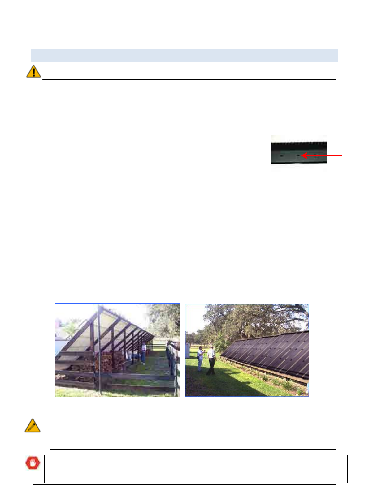
OVERVIEW
eco-Spark®solar heating systems can be either mounted on a roof or on the ground with a blanket
underneath. If a change of angle is necessary a special rack must be constructed.
Before installing the collector, please take the time to read the following instructions to ensure smooth and
successful installation and operation.
Make sure you follow the safety and operation guidelines when installing Magen's eco-Spark® solar
collector.
The general performance and energy savings that you can expect from your solar system will depend upon
several factors: insolation, ambient temperatures, wind and the facility's characteristics.
SAFETY PRECAUTIONS AND REGULATIONS
Magen's solar collectors must be installed by an authorized installer. The installation work must conform
to local authority’s standards and regulations. Consult the appropriate authorities or check with your
local building department concerning local permits and requirements before you begin the job.
Electrical installation must be performed by an individual qualified in electrical installations, and conform
to local regulations.
Warning! Always check that power is turned off before attempting any wiring or electrical hookups,
especially when water is present.
Always exercise extreme caution, care and good judgment when working on or around a roof. Avoid
hazards such as overhead electrical wires or loose shingles/roof tiles. Secure ladders so they will not slip
or fall. Wear shoes with proper tread to prevent slipping on a ladder or slopped roof areas.
Always use approved lifting devices when installing solar systems at heights. All occupational health and
safety issues must be adhered to.
Important: While this manual explains how to install eco-Spark®solar panels properly in typical
situations; it cannot address all the possible individual cases. If you have any installation questions,
contact your sales representative for assistance. As the installing contractor, you are responsible for
fulfilling top quality standards when installing eco-Spark®panels.

Preface Safety precautions and regulations
Magen eco-Spark®Installation manual. © 2012, all rights reserved Page | 6
Important: Avoid walking over the eco-Spark®collectors! Wherever possible, the system should be
installed so that all parts of it are accessible.
Warning! Water in the collector can reach high temperatures (up to 90°C, 194°F)! Take caution while
handling the collector to avoid burns.
Transport and handling
eco-SPARK® solar collectors must be secured during transportation to avoid damage to the packaging,
and scratches to the collector’s cover. Keep the marked side of the package up and consider it fragile.
Keep original package for storage in warehouse and for transporting solar panels prior to the installation.
While in storage or when transported, up to 8 boxes can be stacked on top of one another.
Lightning protection
An authorized lightning protection specialist should be consulted to examine the required lightning
protection measures required. eco-Spark®solar system is made from "all plastic" materials.

Preface Definitions of terms used in this document
Magen eco-Spark®Installation manual. © 2012, all rights reserved Page | 7
DEFINITIONS OF TERMS USED IN THIS DOCUMENT
Module –39 individual tubes connected to 30 cm (1') wide manifold on both ends. Each module is encased
in transparent multi-layer polycarbonate plate.
Panel –Four (4) modules welded to one another at the manufacturing facility. The collector absorbs the sun
rays and transforms them into thermal energy.
PC Glazing –Durable Polycarbonate glazing with a UV blocking layer.
Differential Controller –An electrical device that operates the solar pump, according to a pre-set
temperature difference between the collector temperature and the pool temperature.
Solar Pump –A pump that runs water to/from the collectors and the pool's filtration circuit. Operates
according to the differential controller.
Vacuum/Air Relief Valve –A valve connected to the upper point of the solar system to release trapped air
when the system turns ON, or to allow air into the system when it turns OFF.
MODULES/PANELS/BANKS
eco-Spark® collectors are manufactured as individual "modules", and connected together in the factory in
groups of four modules to form "panels". You connect the supplied panels together to form "banks" of
various lengths, depending on the individual requirements at your site.
An eco-Spark®solar pool heating system consists of one or more banks of collectors, connected to the
swimming pool filtration system.
Module –Modules
come in two lengths,
always 30 cm (1') wide.
Panel –4 Modules
welded to one another
in the factory.

Preface Maximum operation pressure
Magen eco-Spark®Installation manual. © 2012, all rights reserved Page | 8
DIMENSIONS & SPECIFICATIONS
Model Metric Units Spark 40 Spark 30 US Units Spark 40 Spark 30
M.E.E. Cat No.
1237111
1237108
1237111
1237108
Area
[m2]
3.85
2.77
[ft²]
41
30
Length [cm] 323 231 [ft] 10.5 8
Width [cm] 125 125 [ft] 4.1 4.1
Weight (empty) [kg] 17 13.1 [lbs] 37 28
Fluid capacity [l] 11.7 9 [gallons] 3 2.3
Weight (wet)
[kg]
28.7
22.1
[lbs]
63
48
Weight per area (wet) [kg/m
2
] 7.5 8 [lbs/ft²] 1.5 1.6
Recommended flow rate
[l/h]
500-1000
300-800
[gpm]
2.2-2.4
1.3-2.0
MAXIMUM OPERATION PRESSURE
The collectors are designed to operate under a maximum pressure of 4 bar/60 psi.
PRESSURE DROP
The pressure drop of 1 collector is 0.05 bar/0.72 psi (in a recommended flow rate of 500 l/h | 2.2 gpm).
WIND AND SNOW LOAD
When properly installed, the collectors can withstand uplift wind pressure or snow load of at least 1000 Pa.
Maximum operation pressure
Bank –a structure made of several panels joined together with Magen eco-Energy's (MEE) designated
Plastic Pipe Connectors (PPC).

DESIGNING YOUR SYSTEM THE SOLAR SYSTEM LAYOUT
Magen eco-Spark®Installation manual. © 2012, all rights reserved Page | 9
DESIGNING YOUR SYSTEM
This chapter describes the factors you need to take into account when designing your system, and the
process planning of the systems' structure.
During all stages of the design and construction keep in mind that you want to produce a system for the
customer that will be as efficient and as AESTHETICALLY PLEASING as possible.
THE SOLAR SYSTEM LAYOUT
The first thing to do is determine the location of your solar heating system. The following factors must be
taken into account.
COLLECTOR AREA
The total panel area must be large enough to heat the pool efficiently. In addition to the pool's surface area,
the exact optimum size depends on many factors such as: solar radiation intensity, climate, latitude, roof
orientation, slope, winds, pool cover (at night), pool volume and shading.
An approximate “rule of thumb” is to allow for a collector area equal to 60% of the pool's surface.
PROXIMITY TO POOL
The panels need to be as close to the pool as possible to reduce heat loss in the plumbing and
eliminate the need for an additional pump.
LOCATION & ORIENTATION
Ideally the collectors should be mounted on a flat or tilted roof or on an elevated ground mounted rack,
facing south (in the North Hemisphere). Where necessary, East facing or west facing roofs can be used (in
that order of preference). If you have to mount collectors on a north facing slope, it is recommended to
construct a reverse rack.
Tip: For ideal self-cleaning of the glazing it is recommended to install the collector at a minimum angle
of 150.
How to locate the collector on the selected roof? The lower side of the collector is the side where the
Stoppers are connected. Stopper (Cat Num. 1233160) is attached to the edges of every single module (8 in
total) and mounted to the unglazed tubes. The stoppers eliminate the possibility of the glazing moving due
to thermal expansion/contraction and contribute to the collectors' strength and stability.
IMPORTANT: A collector should be installed so the stoppers are located on the lower part of the
collector. A system that will be installed differently will function less efficiently.

DESIGNING YOUR SYSTEM Tilt
Magen eco-Spark®Installation manual. © 2012, all rights reserved Page | 10
TILT
Be sure the planned position of the collector panels allows for them to drain naturally when the pool pump
shuts off.
Tip:
The “ideal” angle for maximum solar collection should be similar to the local latitude or up to 15
o
higher. However, any angle that allows for self-drainage of the panels is sufficient.
Important: Mounting the solar panels in certain locations, and/or constructing a support structure (if
necessary) may require a building permit. Consult with the appropriate authorities, or check with
your local building department, about permit requirements and codes that may apply, before you
begin work.
PREPARING A SCHEMATIC DIAGRAM
Once you have decided on the location for the panels, prepare a schematic diagram of the
system you wish to construct, taking into account the collectors sizes available.
1. Fill in the "Site evaluation sheet” at the end of this document. This will help you decide on
the best system for your site.
2. Prepare a schematic drawing of the installation area. Include the proposed location of the
feed and return lines.
3. Use the panel dimensions on page 8, to sketch the system you will construct.
Important: Large scale or commercials systems must be designed by a professional engineer.
Tip: Roof areas often give the impression of being bigger than they really are, so be sure to actually
MEASURE the available area before making your drawing.
Note: Where possible construct your system using panels of the same length (if possible the largest
length). In cases where space limitations do not allow for a complete panel, individual modules can
be ordered. Modules can then be connected to one another or to panels in exactly the same manner
that panels are connected to each other. Use individual MODULES only if essential.

DESIGNING YOUR SYSTEM
Sample collector system
Magen eco-Spark®Installation manual. © 2012, all rights reserved P a g e | 11
SAMPLE COLLECTOR SYSTEM
Figure 1: Sample collector system
Note: example illustrated above does not allow for natural water drainage and is not suitable for colder regions with
freezing conditions.
1. Feed line climbing to far point from pump house.
2. Air release valve at highest point (optional).
3. CPVC/PPR/PEX pipe connecting across a large obstruction
4. Flat roof
5. Balance valves in the return line.
6. Return line as short as possible, made of high temperature resistant pipe.
Note: Full details of how to connect the supply and return pipes are given on Page 33.
DESIGNING YOUR SYSTEM Mounting racks
Magen eco-Spark®Installation manual. © 2012, all rights reserved Page | 12
MOUNTING RACKS
Important:
The collector must be supported and lying on a rigid surface. It is not a self-supported unit.
Wherever the system is installed, both headers should be elevated 2.5 cm (1") to 5 cm (2") above the
roof/ground, by using stainless steel/wooden profiles. For roof types that might be affected by the heat
radiating from the collector an additional metal/wooden profile should be installed under the binders. The
metal/wooden profiles prevent the collector from coming in direct contact with the roof.
In all installations a minimum of two metal/wooden profiles must be installed as instructed above, to
keep the breathing holes (which are located on the lower surface of the sealing panel) constantly open.
This will eliminate the possibility of water ingress into the glazing.
Where there is no roof space, you may need to construct a rack to mount some
or all of the eco-Spark®panels. The rack must provide a STABLE base for the panels to be secured to.
When designing a mounting rack the following considerations should be taken into account:
The tilt of the rack should be as near as possible to the latitude of the location, to provide optimum
solar collection.
The tilt of the rack must be sufficient to allow the collectors to drain naturally when the pool pump
shuts off as well as for self-cleaning purposes (at least 150).
When calculating the area for the rack, take into account that collectors expand and contract due to
temperature changes under normal working conditions. Allow for additional 10 cm (4'') length per
collector.
Allow room on the rack for the supply and return plumbing and plumbing between collectors and
banks.
The mounting rack must be stable, and able to support the weight of the collectors when filled with
water, which is up to 8kg/m2(1.6 lbs./ft2).
Note: Whenever solar collectors are installed on a rack, a substrate should be mounted on the rack
prior to mounting the panel. This eliminates heat loss and stress created by wind blowing on the back
and sides of the rack.
Breathing
holes
Figure 2: Sample mouting rack
IMPORTANT
: Some local building codes require that the rack construction be approved by an authorized
engineer. Please conform to local building codes and regulations in your region!
Parts and tools Mounting racks
Magen eco-Spark®Installation manual. © 2012, all rights reserved Page | 13
PARTS AND TOOLS
Once you know the layout of your solar collector system, and how many panels/modules you
require, this chapter will help you calculate which eco-Spark®panels and other fittings you will
need to complete your installation.
This chapter deals with the following three categories:
eco-Spark®fittings and accessories
Other fittings
Tools
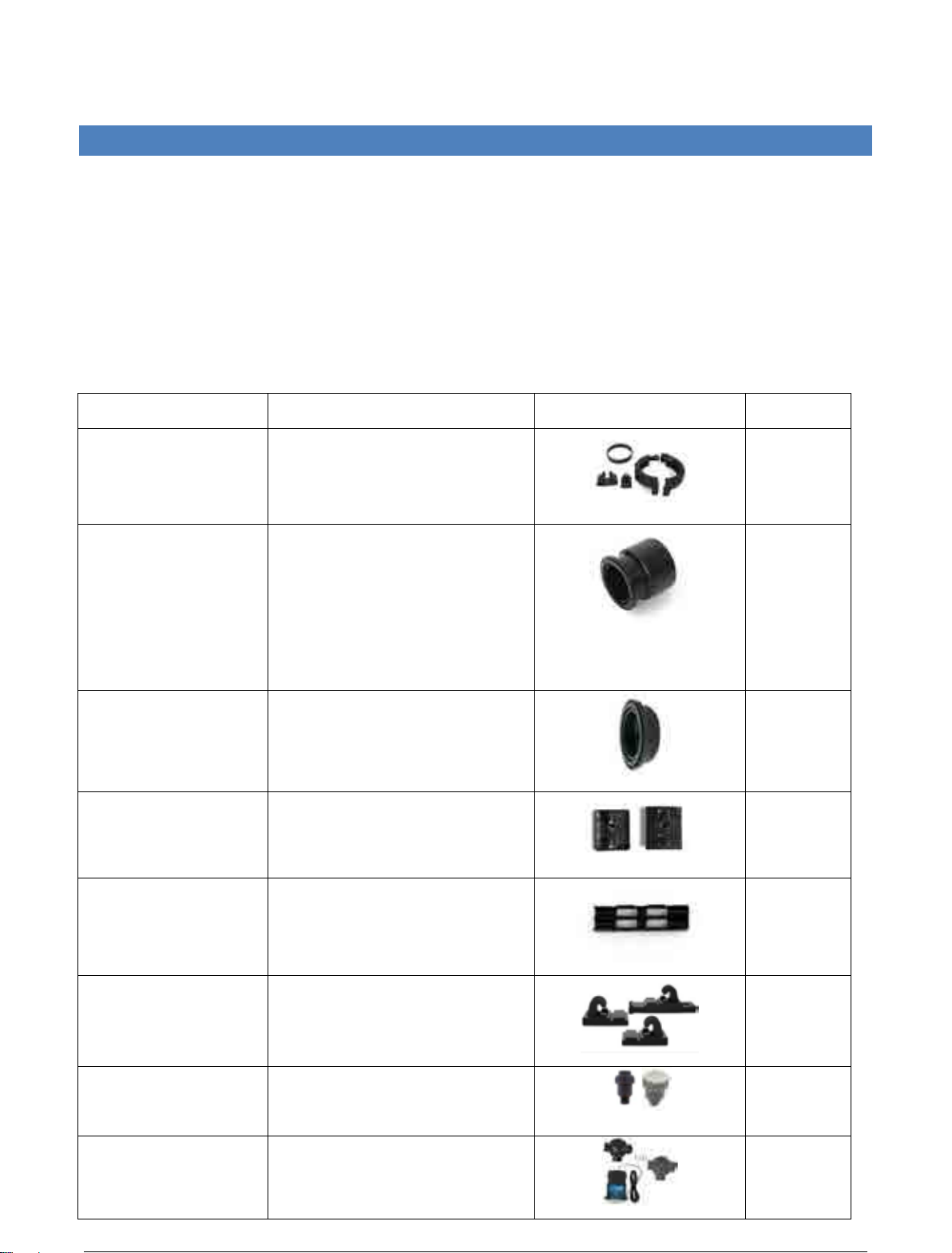
Description Cat. Number Picture Box
PPC SET + Lock 1202320
400
Pipe adaptor CPVC [mm] –420910E
CPVC [inch] –4209100
Polypropylene [mm] –1204000
Polypropylene [inch] –1204100
Polyethylene [mm] –1205000
Polyethylene [inch] –1205100
100
End Cap 1202600
100
Binder (top & bottom) 1202130
Assembled
on panel
Stopper 1233160
Assembled
on panel
Roof mounting pad set
1203100
76
Air/vacuum relief valve
Vacuum relief valve
1201400
1201410
12
Controller + 3-way-
valve set
4201563
1

Parts and tools fittings and accessories
Magen eco-Spark®Installation manual. © 2012, all rights reserved Page | 14
FITTINGS AND ACCESSORIES
This section summarizes the four basic types of connections to and between eco-Spark®panels, using
eco-Spark®fittings.
CONNECTING BETWEEN PANELS/MODULES
To connect one panel to another or a panel to a module, you need a PPC connector set. This consists
of a clamp top and bottom, a rubber gasket, a latch and a latch lock.
When connecting two panels together you need two PPC sets (Cat Num. 1202320), one to connect the
upper manifolds and one to connect the lower manifolds.
Tip: To ensure comfortable assembly, soak top and bottom PPC for 24 hours before installation.
ENDS OF A BANK
When all the panels/modules in a row are connected together you will have four open ends. Two of
these will be connected to the supply and return lines, the other two will usually be blocked with end
caps.
For each bank you will require:
2 end caps (1202600), and
2 pipe adaptors, made from the
same material as the pipelines.
Each of the fittings above is connected with
a PPC.
these will be connected to the supply and return
lines
,
the
other two will usually be blocked with end
caps.
Figure 3: PPC (Plastic Panel Connector) Set
Figure 4: Ends of a bank

Parts and tools Pipes and other fittings
Magen eco-Spark®Installation manual. © 2012, all rights reserved Page | 15
SECURING PANELS TO THE ROOF
Panels are secured to the roof using S Roof Mounting Pads (Cat. Num.1203100). As a general rule of thumb
allow 3 pads per panel, 2 at the upper end and one at the bottom. For steep roofs or windy regions, use 4
units per panel, 2 at the upper end and 2 at the lower end.
ECO-SPARK®FITTINGS SUMMARY
Table 1: Summary of eco-Spark® fittings required
* Make sure that the Pipe Adaptor is made from the same material as the chosen pipelines;
otherwise the connection will come apart.
S Roof
Mounting
Pads
PPC
Connectors *Pipe
Adaptor
End Caps
For each panel 3-4 - - -
Between 2 panels - 2 - -
Between 2 panels
across obstruction
- 4 2 -
For each bank ends - 4 2 2
PIPES AND OTHER FITTINGS
This section deals with pipes and other fittings you will need, that are not supplied by Magen eco-energy.
PIPES
Use only pressure rated pipe with temperature resistance of up to 90 oC (194oF). Make sure that the pipes
are UV resistant where subjected to UV radiation, otherwise use UV protection or a cover. For open loop
installations use only pipes that are certified for drinking water contact. Optional pipe materials are: CPVC,
PEX, PPR.
FITTINGS
Use only pressure and high temperature rated fittings to match the selected pipes. Connections must follow
manufacturer instructions and training if necessary.
Important: Do not use “plumbers” fittings or DWV fittings (Drain, Waste and Vent). Use a quality
brand name product and follow the manufacturer’s directions for use on the product label.
Important: If you cannot obtain black pipes & fittings, and wish to spray paint the fittings black, be
sure to use high quality paint, preferably with UV inhibitors.

Parts and tools
Pipes and other fittings
Magen eco-Spark®Installation manual. © 2012, all rights reserved P a g e | 16
OTHER FITTINGS
Depending on your specific job, you will need various other plumbing items and materials such
as: Valves, stainless steel lag bolts, silicone or polyurethane caulk, silicone spray, galvanized pipe
straps, black electrical wire ties, electrical wire nuts, 18ga-22ga sensor wire, 14ga-16ga electrical
wire with ground, Teflon tape, concrete anchors and screws, electrical conduit, etc. Be sure to
use quality products that will withstand direct sun radiation for many years.
Additional parts you may have to include are:
Air/Vacuum relief valve
Check valve
Ball valve
T-joint
L-joint
3-way valve/ Automatic control
Pipe reductions, bushings, sockets
TOOLS
Standard tools and materials that are useful to have when installing an eco-Spark®systems are:
Basic toolbox
Chalk
String
Electric wire (to connect to
automatic control)
Cable for sensor
Measuring tape
Flat head and Phillips head
screwdrivers
Channel lock pliers
Power drill with bits
Caulking gun
Pipe cutter or hacksaw
Ladder
Garden hose
Hand saw
Chisel

hydraulics Panel configurations
Magen eco-Spark®Installation manual. © 2012, all rights reserved Page | 17
HYDRAULICS
This chapter deals with the hydraulics that demands consideration before installation.
PANEL CONFIGURATIONS
Before you can start constructing the system you have designed, you must consider how the
banks will be connected together. You must also take into account the maximum number of
panels allowed per bank, as shown below.
Table 2: Maximum number of panels allowed per bank
Panel type Max. bank size
SPARK-30 (4’x8’) - Cat. 1237108 12
SPARK -40 (4’x10.5’) - Cat. 1237111 10
These numbers may be exceeded if there is high-pressure flow or substantial back pressure on
the system that will force adequate flow through every panel. In other cases you should divide
the bank into two using one of the following configurations.
Banks in parallel can also be used for smaller installations, when space is limited.
Important:
Large scale or commercials systems must be designed by a professional engineer.
BASIC PLUMBING & ARRAYS LAYOUTS
END
CAP
SINGLE BANK
FEED
ROOF TILT
RETURN
END
CAP
END
CAP
BANKS IN PARALLEL
FEED
ROOF TILT
RETURN

hydraulics
Plumbing
Magen eco-Spark®Installation manual. © 2012, all rights reserved P a g e | 18
PLUMBING
WATER INLET /OUTLET
Inlets are always connected to a lower end of the bank; Outlets to the opposite upper
corner (diagonally).
It is best to connect the inlet to the corner farthest from the pool, so that the outlet can
be as near the pool as possible, to reduce heat loss.
Using the “Reverse return” (Tichelmann) method would ensure balanced flow in all
collector banks.
BANKS IN SERIE
FEED
ROOF TILT
END
CAP
END
CAP
RETURN
SINGLE BANK SPLIT FEED
FEED
ROOF TILT
END
CAP
END
CAP
RETURN
END
CAP
END
CAP
BANKS IN SERIES
FEED ROOF TILT
RETURN
BANKS IN SERIES

hydraulics Plumbing
Magen eco-Spark®Installation manual. © 2012, all rights reserved Page | 19
PIPE DIAMETER
It is important that all plumbing connected to the system uses a diameter of pipe appropriate to the size of
your solar array. Insufficient pipe diameter will unnecessarily restrict water flow to the panels. Use the
following as a guide:
Table 3: Recommended pipe diameters
Flow Rate Recommended pipe diameter
0 - 9 m3/h (0 –40 gpm) 50 mm (2’’)
9 -15 m3/h (40 –66 gpm) 63 mm (2.5’’)
15 - 21 m3/h (66 –92 gpm) 75 mm (3’’)
For larger flow rates you may need to incorporate alternative series-plumbing techniques.
PLUMBING RUNS
Plumbing runs should be as short as possible, especially the “Hot Return” pipe (to minimize
heat loss).
Pipes should be supported every 1.2 m (4') for horizontal pipe runs or 2.5 m (8') for vertical
pipe runs to prevent sagging and movement.
Tip:
Since 90° elbow fittings greatly restrict water flow, use as few of these as possible. In some
cases two 45° fittings can be used in place of a 90° fitting.
Tip: When clamping pipes that run across the roof, use clamps that allow for expansion of the
pipe in hot weather. For very long pipe runs, expansion fittings may be employed. See
manufacturer for recommended size, spacing and techniques for installation.
Tip: When clamping pipes on the side of a building use clamps with a diameter equal to the pipe
diameter, to prevent vibration and to assure a professional looking installation.
BALANCED FLOW
If you install a split system (feed), such as one of those shown in the former page, it is essential that the
piping is connected exactly as shown, to ensure equal water flow through both banks of panels. Water
follows the path of least resistance, so if one plumbing run is shorter, more water will flow through it than
through the longer one. This should also be kept in mind when designing a panel layout different to those
shown. For larger, more complicated configurations “balancing valves” may be necessary to maintain equal
water pressure in all parts of the system.

hydraulics Plumbing
Magen eco-Spark®Installation manual. © 2012, all rights reserved Page | 20
PUMP POWER
The power of the swimming pool filtration pump must be adequate to supply the eco-Spark®system
with enough flow & pressure to provide the recommended parameters. These recommended rates
are detailed in the table below:
Table 4: Recommended flow rate through the panels
Panel type
Recommended Flow per Panel
Spark-30 (4’x8’)
1237108
>300 lit/hr (>1.3 gpm)
Spark-40
1237111
(4’x10.5’)
>500 lit/hr (>2.2 gpm)
For example: If you were installing ten eco-Spark-40 (4'x10.5’) panels installed in parallel, your pump would
have to be able to deliver >5000 liters/hr (22 gpm) to the solar array. These recommended flow rates may be
exceeded by as much as 100% without any detrimental impact on the performance of the system. The
existing pool filtration pump is usually adequate only for circulating the water and not for running the water
through the solar system.
Generally, a 1 horsepower pump (0.75KW) is sufficient for a standard private pool solar system, unless there
is an unusually long pipe run, a high roof, or a large number of panels. If you are not sure what your pump
flow rate is, consult your Dealer or Pump Manufacturer for the pump’s flow characteristics.
AUTOMATIC DRAINAGE
The panels and the pipe must be installed so that the water drains out of them when the pool pump shuts
off. This is especially important in areas where freezing occurs.
To allow for drainage, a vacuum breaker (marked as # 5) is installed on the solar feed line above the 3- way
valve, as shown in the drawing on page 34.
COMPENSATING FOR LACK OF AUTOMATIC DRAINAGE
If, due to unusual roof design, flat roof or pool equipment location, it is not possible to achieve complete
automatic drainage, manual drain down valves must be installed in appropriate places in the plumbing, or at
the end of the bottom (feed) header.
Instead of installing an End Cap at the end of the header, place an Air/Vacuum relief valve (Cat. Num.
1201400) along with a ball valve for manual drain. These valves should be opened when the system is being
shut down for the winter months or when outdoor temperatures approach freezing point.
Important: eco-Spark
®
solar pool panels are NOT warranted against internal freezing. To avoid
damage install the collectors in a manner that allows for automatic draining.
Reminder: eco-Spark®system is not resistant to temperatures below freezing point.
Table of contents
Popular Lighting Equipment manuals by other brands


Equinox Systems
Equinox Systems ARIES EQLA20 user manual

Lightmaxx
Lightmaxx Platinum Line LED Strobe X3 user manual

Chauvet Professional
Chauvet Professional REM-RB100CM IP Quick reference guide

RANCEO
RANCEO See Snake CLH15 instruction manual

CALI
CALI lipLEDs LLED8200-PC-PLM installation instructions

Rosco
Rosco MIRO CUBE 2 user manual


