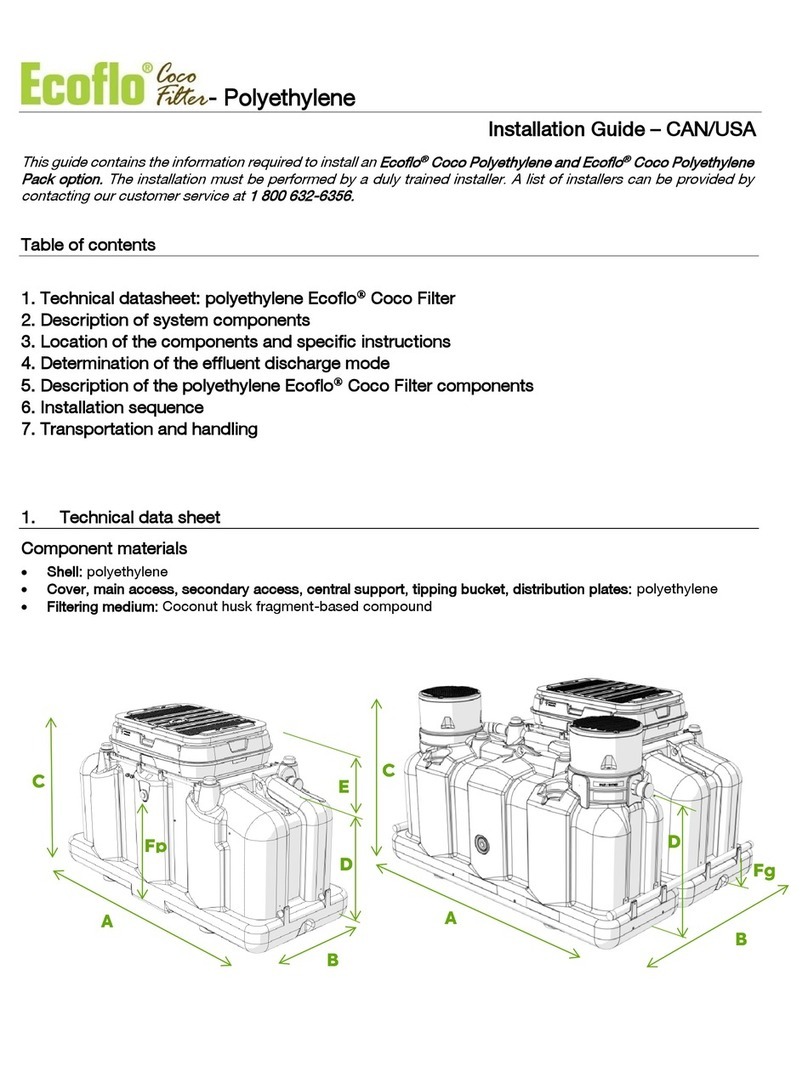
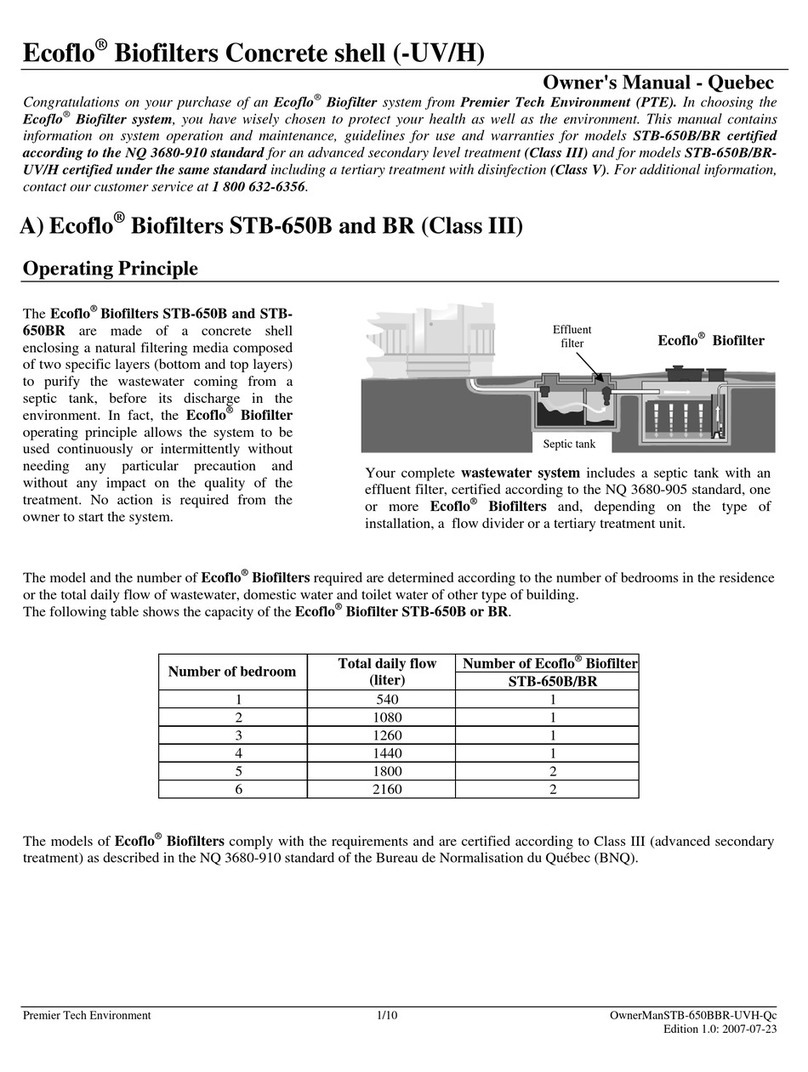
Ecoflo ST-500 User manual

Premier Tech Aqua 1/13 Ecoflo®Fiberglass –Installation guide Ontario
Édition : 2017-05-08
Ecoflo®Biofilter-Fiberglass open bottom
Installation Guide-Ontario
This guide contains the information required to install a Fiberglass Ecoflo®Biofilter Certified under the CAN/BNQ
3680-600 requirements. The installation must be performed by an authorized installer. A list of installers can be
provided by contacting our customer service at 1 800 632-6356.
Table of Contents
1. Technical data on the polyethylene Ecolfo®Biofilter
2. Description of system components
3. Location of components and specific instructions
4. Description of fiberglass Ecoflo®Biofilter components
5. Installation sequence
6. Storage, handling and shipping (consult the Storage, Handling and Shipping Guide on
ptzone.premiertechaqua.com)
7. Typical installations (visit ptzone.premiertechaqua.com to obtain the complete list)
1. Technical data
Component material
Shell : composite fiberglass and polyester resin;
Cover, central support, tipping bucket, distributiom plates and sampling device: polyethylene
Filtering media: natural fiber
* See drawings on next page.
** Weights are approximate and not binding (for handling and lifting purposes only).
Modèles
ST-500
ST-650
ST-750
Demand dosed
Time dosed
Demand dosed
Time dosed
Demand dosed
Time dosed
Hydraulic capacity
1 540 L/d
1 925 L/d
2 000 L/d
2 500 L/d
2 310 L/d
2 890 L/d
Treatment surface area
5,2 m²
6,5 m²
7,5 m²
Type of disposal
Infiltration
Infiltration
Infiltration
Type of bottom
Open
Open
Open
Lenght(A)*
3 345 mm (11')
4 175 mm (13' 8")
4 675 mm (15' 4")
Width (B)*
2 361 mm (7' 9")
2 361 mm (7' 9")
2 361 mm (7' 9")
Height (C)*
1 320 mm (4' 4")
1 320 mm (4' 4")
1 320 mm (4' 4")
Inlet Height (D)*
970 mm (3' 2")
970 mm (3' 2")
970 mm (3' 2")
Inlet Height (E)*
350 mm (1' 2")
350 mm (1' 2")
350 mm (1' 2")
Weight** of the shell
105 kg (230 lb)
125 kg (275 lb)
145 kg (320 lb)

Premier Tech Aqua 2/13 Ecoflo®Fiberglass –Installation guide Ontario
Édition : 2017-05-08
2. Description of system components
2.1 Primary treatment
The primary treatment consists of a primary reactor which clarifies wastewater by letting suspended solids settle to
the bottom and retaining floating matter to avoid clogging the treatment system located downstream. An effluent
filter is installed at the outlet of the primary reactor. All primary reactors and effluent filters must comply with local
regulations.
Regardless of the septic system, opting for a primary reactor that is larger than as specified in the regulation will
contribute to improved effluent treatment performance. The Ecoflo® Biofilter can be installed with a concrete or
polyethylene primary reactor.
The effluent filter contributes to extending the useful life of any treatment system by reducing the solids in the
wastewater before it is discharged from the primary reactor. The use of an effluent filter is especially important if a
residence is equipped with a garbage disposal unit, a sewage pump or any other device that could increase the
quantity of suspended matter in the wastewater and lead to premature clogging of the treatment system. In the
case of Demand dose only, the effluent filter incorporates a flow control device.
2.2 Dosing tank and control unit (Time dosed biofilter only)
A dosing tank of sufficient volume must be installed downstream from the primary reactor to feed the Ecoflo
Biofilter. The dosing tank’s pump is connected to the PTA DCU-100 simplex control panel or the equivalent to feed
the Ecoflo®Biofilter 20 hours per 24-hour period. Premier Tech Aqua recommends feeding each Ecoflo®Biofilter
between 30 and 40 litres (8 and 10 US gallons) per hydraulic event.
2.3 Ecoflo®Biofilter
Once the primary treatment is complete, the wastewater flows from the
primary reactor to the Ecoflo®Biofilter, where it flows into a tipping
bucket that equally distributes it along the distributor plates installed on
either side of a central support. The wastewater then trickles through a
filtering media composed of natural fibers. The organic matter
contained in the wastewater is then consumed by the microbial flora
fixed onto the particles that compose the filtering media
Finally, the treated effluent is discharged into the environment, either by infiltration in an absorption bed located
directly under the Ecoflo®Biofilter or release into a watercourse, provided certain conditions are met and in
accordance with local regulations.
To ensure effective treatment, there must be enough oxygen present
in the system to feed the microorganisms in the filtering media. Air
enters the system through vents located on the main access cover.
Depending on the biofilter model used by the treatment system, the
pumping station and/or central support allows air to circulate
between the surface and base of the filtering media. Air circulates
throughout the system by way of convection from the residence’s
vent (or a standalone vent) through a feed pipe to the primary
reactor.
An Ecoflo®Biofilter’s operating principle allows the system to be
used continuously or intermittently without requiring any special precautions or having any impact on the quality of
the treatment. In most cases, no specific action from the owner is required to start the system.
The Ecoflo®Biofilter model and number of units required are determined based on the number of bedrooms in the
residence or the total daily volume of domestic wastewater generated by any other type of building. It is also
determined in accordance with the surface area and existing topography and soil characteristics (nature,
permeability, depth).
Air flow diagram
To vent of the house or
independant vent
Primary treatment
Air flow diagram

Premier Tech Aqua 3/13 Ecoflo®Fiberglass –Installation guide Ontario
Édition : 2017-05-08
There are many different Ecoflo®system models, and each model has different characteristics: type of shell used,
treatment capacity based on the number of bedrooms and presence or not of a recovery pump built into the shell.
Ecoflo Biofilter
Shell (type of)
Polyethylene
Treatment capacity
5.2 = 1 600 L/d Demand dosed or 2 000 L/d Time dosed
6.5 = 2 000 L/d Demand dosed or 2 500 L/d Time dosed
7.5 =2 310 L/d Demand dosed or 2 890 L/d Time dosed
Bottom (type of)
Open
3. Location of components and specific instructions
Installation diagrams (demand dosed)
3.1 Minimum distances to be maintained in accordance with the regulation in force
In the case of an isolated dwelling, a wastewater treatment system must be installed in a place:
where there is no motorized traffic;
where it is not likely to be submerged;
that is accessible for haulage and maintenance;
that complies with the distances in the following table:
Minimum distances to be maintained in accordance with the regulation in force and Premier Tech Aqua
specifications*
Reference point
Primary reactor
Infiltration Zone* of Ecoflo® Biofilter
Residence
1,5 m (5')
5 m (16,5')
Drain line
**
5 m (16,5')
Property limits
1,5 m (5')
2 m (6,5')
Top of a talus
**
3 m (10')
Water well or source
15 m (50')
30 m (100')
Tube well
15 m (50')
15 m (50')
Drinking water line
1,5 m (5')
2 m (6,5')
Swamp or pond
10 m (33')
15 m (50')
Lake or watercourse
À l’extérieur de la bande riveraine
15 m (50')
Vehicle or object weighing ≥225 kg (500 lbs.)
**
5 m (16,4')***
* The infiltration zone comprises a layer of crushed stone laid down directly under the biofilter or discharges into the environment.
** Refer to the manufacturer’s specifications.
*** Distance calculated from the cover of the Ecoflo®Biofilter.
Primary reactor with
effluent filter
Ecoflo®Biofilter

Premier Tech Aqua 4/13 Ecoflo®Fiberglass –Installation guide Ontario
Édition : 2017-05-08
3.2 Installation conditions
3.2.1 Primary reactor
The primary reactor must be installed in compliance with the following instructions:
Both openings must be extended to the soil surface through watertight and insulated chimneys and equipped
with watertight covers;
The depth of the backfill piled over the tank must not exceed 90 cm (36 in.);
The installation must be 100% watertight and only receive the residence’s domestic wastewater (no foundation,
land or roof drainage);
The primary reactor must be placed where it is not at risk of being flooded or submerged (depending on the
situation, it may be necessary to provide for drainage around the primary reactor to prevent groundwater from
reaching a level that would pose a flooding risk);
The manufacturer’s specifications.
3.2.2 Fiberglass Ecoflo® Biofilter
The Ecoflo®Biofilter must be installed in compliance with the following recommendations and it is important to
notify all stakeholders (installer, landscaper, owner, snow removal company, etc.) of them to prevent damage to
the wastewater processing system components.
Ensure access to the covers of your septic installation at all times. NEVER cover them with mulch, soil or a fixed
structure.
Once your septic installation has been completed, the covers must be 50 mm (2 in.) higher than the surface of
the landscaped terrain.
NEVER install extensions over the access of the polyethylene Ecoflo®Biofilter.
NEVER plant trees within 2 m (6.5 ft.) of the infiltration zone.
NEVER connect a land or foundation drainage line, gutter spout, sump or bilge pump or air conditioner drain to
your septic installation.
NEVER pile up more than 300 mm (12 in.) of backfill on the shell.
NEVER drive a vehicle or place objects weighing more than 225 kg (500 lbs.) within a radius of 4 m (13’ 1’’.)
from the covers of the Ecoflo® Biofilter.
Ensure a rapid regrowth of the vegetation to prevent soil erosion.
Ensure that the maximum seasonal groundwater level never exceeds the base of the shell.
Also, the fiberglass Ecoflo®Biofilter must be installed in a location:
Where the soil is permeable or very permeable;
That is never susceptible of being flooded or submerged by ground water. If that is the case, an Ecoflo
Biofilter with a watertight bottom should be used. Please contact our customer service department for further
information.
By respecting these guidelines, you contribute to the proper operation of your wastewater treatment system. Failure
to abide by these guidelines may void the warranty, at Premier Tech’s discretion
3.2.3 Dosing tank and control unit (Time dosed biofilter only)
The dosing tank and the control panel must be installed in compliance with the manufacturer’s specifications.

Premier Tech Aqua 5/13 Ecoflo®Fiberglass –Installation guide Ontario
Édition : 2017-05-08
4. Fiberglass Ecoflo®Biofilter component description
PLEASE CONSULT THE ILLUSTRATION ON FOLLOWING PAGE
Lid
Access port for maintenance and inspection;
Provides proper air flow through the system (via air intake);
Secures access with bolted assemblies.
Insulating board
Thermally insulates the system;
Guides airflow into the shell's air ducts;
Seals the system (with tie-wraps).
Shell
Encloses the system's components;
Allows connection of water and air pipes;
Distributes air throughout the filtering media via the air ducts.
Central support
Supports the tipping bucket and one end of the distribution plates;
Allows air circulation between bottom and top of the filtering media.
Allows to inspect the state of the filtering media via its access.
Tipping bucket
Evenly distributes the wastewater on both sides of the filtering media;
Creates hydraulic events required for proper distribution of the wastewater on the distribution plates and, at the
same time, contributes to the self-cleaning of the plates.
Distribution plates
Allow even distribution of the influent on the surface of the filtering media.
Filtering media
Consists of a natural fibre-based filtering media;
Promotes good biomass growth which is essential to biological treatment of the wastewater;
Physically filters the solids contained in the influent;
Maintains adequate humidity level required for biomass viability when there is no water going through the
system for a certain amount of time.
Dispositif d’échantillonnage
Allows to collect samples of the effluent treated by the system.
Sampling device could be installed internally or externally.

Premier Tech Aqua 6/13 Ecoflo®Fiberglass –Installation guide Ontario
Édition : 2017-05-08
Exploded view of the system
Filtering media
(top layer)
Filtering media
(bottom layer)

Premier Tech Aqua 7/13 Ecoflo®Fiberglass –Installation guide Ontario
Édition : 2017-05-08
5. Installation Sequence
NOTE: The installer is responsible for the implementation of safety measures throughout the installation
(i.e. wearing a hard hat, gloves, boots, safety glasses, mask, etc).
5.1 Make sure you have all the following components
A. 1 fiberglass shell including :
1 bag (not illustrated) with the owners documents;
6 plastic tie-wraps;
1 insulating board;
B. 1 lid;
C. 1 tipping bucket;
D. 4 distribution plates;
E. 1 sampling device;
F. 1 central support;
G. 1 pallet of filtering media (bags # 1 «bottom
layer» and bags #2 «top layer»).
For any problem, broken or missing part,
contact Premier Tech Aqua at 1 800 632-6356
5.2 Infiltration zone, sampling device and central support
Prepare the absorption bed according to the standards specified in the applicable Design Guide.
Use clean crushed stone with a diameter of 15-60 mm (½"-2"). It is strongly recommended to use crushed
stone with a diameter of 20 mm (¾");
Make sure the minimum thickness of the bed is 200 mm (8").
Then, place the sampling device on the bed of crushed stone, making sure the flat part is installed on the left side
of the inlet pipe (when looking at the absorption bed from the septic tank). The sampling device’s receptacle must
be located in the center, underneath the central support.
Properly level the central support and make sure it is fully in contact with the surface of the crushed stone.
IMPORTANT:
Never install the Ecoflo®Biofilter’s absorption bed within 2 m (6.5') of a tree.
Never install a riser on the fiberglass open bottom Ecoflo®Biofilter –the depth of the absorption bed is
therefore very important.
NOTE: if the existing regulations allow an installation in low permeability soil, consult the Installation Guide of the
Collecting bucket used for low permeability soil in the Fiberglass Section at ptzone.premiertechaqua.com in order
to improve water infiltration in the soil.
G
D
E
B
F
C
A

Premier Tech Aqua 8/13 Ecoflo®Fiberglass –Installation guide Ontario
Édition : 2017-05-08
5.2.1 Surface installation on a sloped site
On a sloped site, the shell should be placed perpendicular to the slope;
The profile of the lot should be such that surface runoff flows away from the Ecoflo®Biofilter and the
absorption bed. If necessary, the profile should be modified;
To account for water released into the soil by the Ecoflo®Biofilter, the base of the retaining wall must be well
drained to ensure that the soil and septic system remain stable;
Make sure there is a minimum distance of 6 m (20') between the biofilter’s lid and the retaining wall;
Make sure there is a minimum distance of 3 m (10') between the absorption bed and the retaining wall;
If there is no retaining wall, the backfill material as well as the backfill technique must ensure the stability of the
system in order to avoid the Ecoflo®Biofilter’s displacement.
5.3 Placing and levelling of the shell
Place the shell on the central support, making sure that the
central support is embedded in the shell. The central support
chimney must be opposite the water inlet.
Double check to make sure the shell and the central support
are both levelled and fully in contact with the surface of the
clean crushed stone.
NOTE: Never install a riser on the fiberglass open bottom Ecoflo®Biofilter.
5.4 Geotextile installation and initial biofilter backfill
Place a geotextile (polymeric membrane permeable to air and water) on top of
the crushed stone, around the shell only, to protect the stone from
contamination or obstruction from objects or particles. Do not place any
geotextile under the Ecoflo® Biofilter.
For the initial biofilter backfill, begin by stabilizing the shell by carefully
backfilling each of the four corners. Then backfill the two long sides followed by
the two short sides, using successive 30 cm (12") layers. The backfill material
must be placed with care, not dumped, which is why using a bulldozer for this
step is not recommended.
Backfill the fiberglass units with sandy material up to 50 mm (2") below the lid.
The backfill material should not contain any organic matter, impervious soil,
stones, rocks, debris or other object that could damage the shell. The shell
should not be overloaded with backfill material or with heavy equipment.
Protective barriers/markers should be installed during landscaping to keep
vehicles from driving over the biofilter.
5.5 Water supply pipe connection
Connect the water supply pipe from the primary/septic tank to the water intake of
the Ecoflo®Biofilter, making sure that the entire length of the pipe is on a constant
downwards slope that slants towards the Ecoflo®. Note that the soil under the
pipes must be properly compacted.
In the case of a gravity fed installation with two (2) Ecoflo®Biofilters, a flow divider
is required. Premier Tech Aqua offers two types of gravity flow dividers: the gravity
flow divider GFD-200 and the gravity flow director GFD-200A.

Premier Tech Aqua 9/13 Ecoflo®Fiberglass –Installation guide Ontario
Édition : 2017-05-08
Demand dose: gravity feeding of the Ecoflo®
Connect the supply line from the septic tank to the water intake of the Ecoflo®
Biofilter, making sure that the entire length of the pipe is on a constant
downwards slope that slants towards the Ecoflo®Biofilter. Note that the soil
under the pipe must be properly compacted. The Ecoflo®Biofilter is equipped
with a standard flexible intake adaptor. Use a regular pipe clamp to make the
connection. Remove the protective cap before connecting the inlet pipe. Do not
discard the documents wrapped under the cap: they must be handed over to
the owner.
Time dosing configuration
When a pumping station is required upstream of an Ecoflo® Biofilter, the following instructions must be taken into
account:
When a pumping station is required Premier Tech Aqua recommends sending approximately 30 to 40 L (8 to 10
US gallons) of wastewater to the Ecoflo® Biofilter every pump dosing cycle (10 tipping bucket events);
The pumping station must be watertight (infiltration and exfiltration);
The water supply pipe (flexible 38 mm (1½") Ø pipe) is connected to an inlet adapter which allows the
connection to the Ecoflo®Biofilter’s 100 mm (4") Ø inlet pipe. Note that the adapter is mandatory to break the
stream of water coming from the pumping station;
An air duct must connect the pumping station to the Ecoflo®Biofilter to ensure air circulation. This air duct is
connected to the adapter, which is equipped with a tee-Y;
Depending on site conditions, a forced air vent may be required;
The pumping station must be accessible at all times.
When an installation consists either of two Ecoflo®Biofilters which cannot be fed by gravity or of three Ecoflo®
Biofilters, a pumping station combined with a pressurized flow divider is required.. Premier Tech Aqua offers
several pressurized flow dividers. For more information on Premier Tech Aqua’s pressurized flow divider, consult
the Peripherals Section at ptzone.premiertechqua.com.
Primary
tank
Dosing tank
Air circulation pipe
Ecoflo®Biofilter
Water supply line
Inlet adapter

Premier Tech Aqua 10/13 Ecoflo®Fiberglass –Installation guide Ontario
Édition : 2017-05-08
5.6 Final backfill and filtering media installation
Complete the backfill. The backfill material must be placed with care and not dumped
(do not compact with bulldozer). The backfill material must be sandy with no rocks or
stones. Allow space for ground cover and make sure the lids are at least 50 mm (2")
above the surface of the landscaped lot. Never install a riser on the fiberglass open
bottom Ecoflo®Biofilter.
Fill the Ecoflo® Biofilter with the filtering media. Pour the filtering media bags with
equal amounts on each side of the central support up to the base of the distribution
plates.
Start with Bags #1 identified « bottom layer » and complete with Bags #2 identified
« bottom layer»
Use a rake to level the surface of the filtering media. The final surface of the filtering
media should be just below the distribution plates.
Be careful! Avoid compacting the filtering media (don’t walk on it).
5.7 Distribution plate installation
Install the distribution plates by placing them on their support rails at both ends of the shell.
The arrow on the distribution plates must be oriented towards the shell’s extremities.
Place the first plate on the left side, followed by a second plate on the right side, fitting it onto the edge of the
first plate.
Follow this same procedure for the other side of the shell (two plates on each side).
The distribution plates should rest on top of the central support and must be attached to it with four plastic tie-
wraps provided for this purpose.
5.8 Tipping bucket installation

Premier Tech Aqua 11/13 Ecoflo®Fiberglass –Installation guide Ontario
Édition : 2017-05-08
Attach the tipping bucket to the central support by inserting the locking catches into the central support's anchor
slots. Press the opposite end down into position and make sure the tipping bucket stays in place. Check the state
of the tipping bucket by moving it from left to right to make sure nothing is blocking its movement.
5.9 System verification and warranty seals
The installed system is certified under CAN/BNQ 3680-600 (2009) and correspond to a B-IV treatment class.
After making sure the tipping bucket is fully operational and that the distribution plates are installed properly,
install the insulating board inside the main access. Seal it shut by attaching the handle of the insulating board to
the access of the Ecoflo® Biofilter using the plastic fasteners. Finally, close the lid of the Ecoflo® Biofilter.
Note that the owner does not have to do anything in particular to start the system.
IMPORTANT REMINDERS
NEVER cover or bury the lids of your septic system. Always keep the lids accessible.
The lids of you septic system must be at least 50 mm (2") above the surface of the landscaped lot.
NEVER install a riser on the access of a fiberglass open bottom Ecoflo®Biofilter.
NEVER plant a tree within 6 m (20') of the Ecoflo®Biofilter lid and within 2 m (6.5') of the absorption bed.
NEVER open the lids or go inside the septic tank or biofilter.
NEVER connect a drain pipe, roof gutter, sump pump or air conditioning drain to your septic system.
NEVER operate a vehicle or place objects weighing over 225 kg (500 lbs) within 5 m (16.5') of the lid. Pass
on this information to all those who have access to your system (landscaper, snow blower, etc.).
NEVER let anything accumulate on top of your septic system (for example: compacted snow). The overload
could damage the system.
NEVER empty the backwash of a spa or pool into your septic system.
NEVER empty wastewater of a recreational vehicle (camping trailer, caravan, etc.) into your septic system.
NEVER use automatic toilet cleaners.
If there is a delay in finishing the landscape after the initial installation of the system, place reference posts
and protective fences to identify the location of the Ecoflo®Biofilter. This will prevent any circulation on the
unit and help indicate the system's final level.
If a pumping station is installed upstream of the Ecoflo®Biofilter, an airflow duct must be connected from
the pumping station to the Ecoflo®Biofilter.
Households must be equipped with an air vent that is in proper working condition and complies with the
applicable standards. Premier Tech Aqua strongly recommends using a 100 mm (4") Ø pipe.
Don’t forget the inspection permit, where applicable.

Premier Tech Aqua 12/13 Ecoflo®Fiberglass –Installation guide Ontario
Édition : 2017-05-08
Hand over the package containing the Owner's Manual and the Maintenance Agreement to the customer.
Remind the customer to fill out and sign the Maintenance Agreement. The customer must keep the white
copy, give the yellow copy to the municipality, and send the pink copy to Premier Tech Aqua.
By respecting these guidelines, you are contributing to the proper operation of your wastewater treatment
system. Failure to abide by these guidelines may, at Premier Tech Aqua's discretion, render the warranty invalid.
6. Handling and Shipping
6.1 Shipping from the distributor to the installation site
Use a trailer or vehicle with adequate loading space depending on the dimensions of the system;
Use appropriate straps to support the systems properly and securely;
When possible, the lifting rings should be used to load the Ecoflo®Biofilter on the trailer or vehicle;
The carrier is responsible for complying with all laws and codes in effect;
The carrier is responsible for any damage caused to the system occurring during shipment.
6.2 Handling
Avoid using handling methods that could damage the system;
Use the four (4) lifting rings of the shell to unload the system. If a forklift is used, make sure the forks are long
enough to support the whole system;
The handler is responsible for any damage caused to the system occurring while handling.
6.3 Loading configuration
The loading configuration depends on the type of transportation used to carry the biofilter to the installation
site;
The loading area must have a surface of at least 4.2 m x 2.4 m (14' X 8') for the biofilter to fit completely;
The carrier must make sure there is enough space to transport the filtering media bags (the bags can be taken
off the pallet). A pallet of filtering media has a surface area of approximately 1.5 m x 1.2 m (5' X 4').
If you have any problems, questions or comments, do not hesitate
to contact Premier Tech Aqua at 1 800 632-6356.

Premier Tech Aqua 13/13 Ecoflo®Fiberglass –Installation guide Ontario
Édition : 2017-05-08
7. Typical installations
The type of installation varies according to the conditions encountered in the field. Here are different types of
installations:
Demand dosed : Gravity feeding of the Ecoflo®
Time dosed : On demand feeding of the Ecoflo
If you have any questions or comments, do not hesitate to
contact Premier Tech Aqua at 1 800 632-6356.
The information contained in this document is based upon the latest information available at the time of publication and is
designed to provide you with a general introduction to our products. We make no warranties or representations as to its accuracy.
We are continually upda-ting and improving our products and reserve the right to amend, discontinue, alter or change
specifications and prices without prior notice. Ecoflo®is a brand of Premier Tech Ltd. The Ecoflo®Biofilter is protected under
patents: CA2499637; US7097768; ES2285173; EP1539325 (BE, FR). Notice issued on 2016-01-12. For current data regarding all
patent application(s) and patent(s) for this product or any part thereof, consult the website patentmarking.premiertech.com
(references: 3685).
© Premier Tech Ltd, 2017
Ecoflo®Biofilter
Dosing tank
Primary reactor
with effluent filter
Ecoflo® Biofilter
Primary reactor
with effluent filter
This manual suits for next models
2
Other Ecoflo Water Filtration System manuals
Popular Water Filtration System manuals by other brands
GE
GE GXWH20S installation instructions

Spectra Watermakers
Spectra Watermakers Newport 400c Installation and operating manual

TLV
TLV SF1 instruction manual
Watts
Watts QTSTMMAX-2S-10M Installation, operation and maintenance manual

Bayrol
Bayrol Automatic Cl/pH Instructions for use

Zen & Pur
Zen & Pur OSMOSEUR ORIGINE user guide

Boneco
Boneco IONIC SILVER STICK Instructions for use
Grizzly
Grizzly G0738 owner's manual
Brita
Brita PROGUARD Gastronomy 200 manual

Envirco
Envirco MAC 10 LEDC/IQ Standard Operation & maintenance manual
Applied Membranes
Applied Membranes AAA-125P MANUAL FOR INSTALLATION, OPERATION AND MAINTENANCE
BWT
BWT VIZION HRS-100 Installation and operation manual
