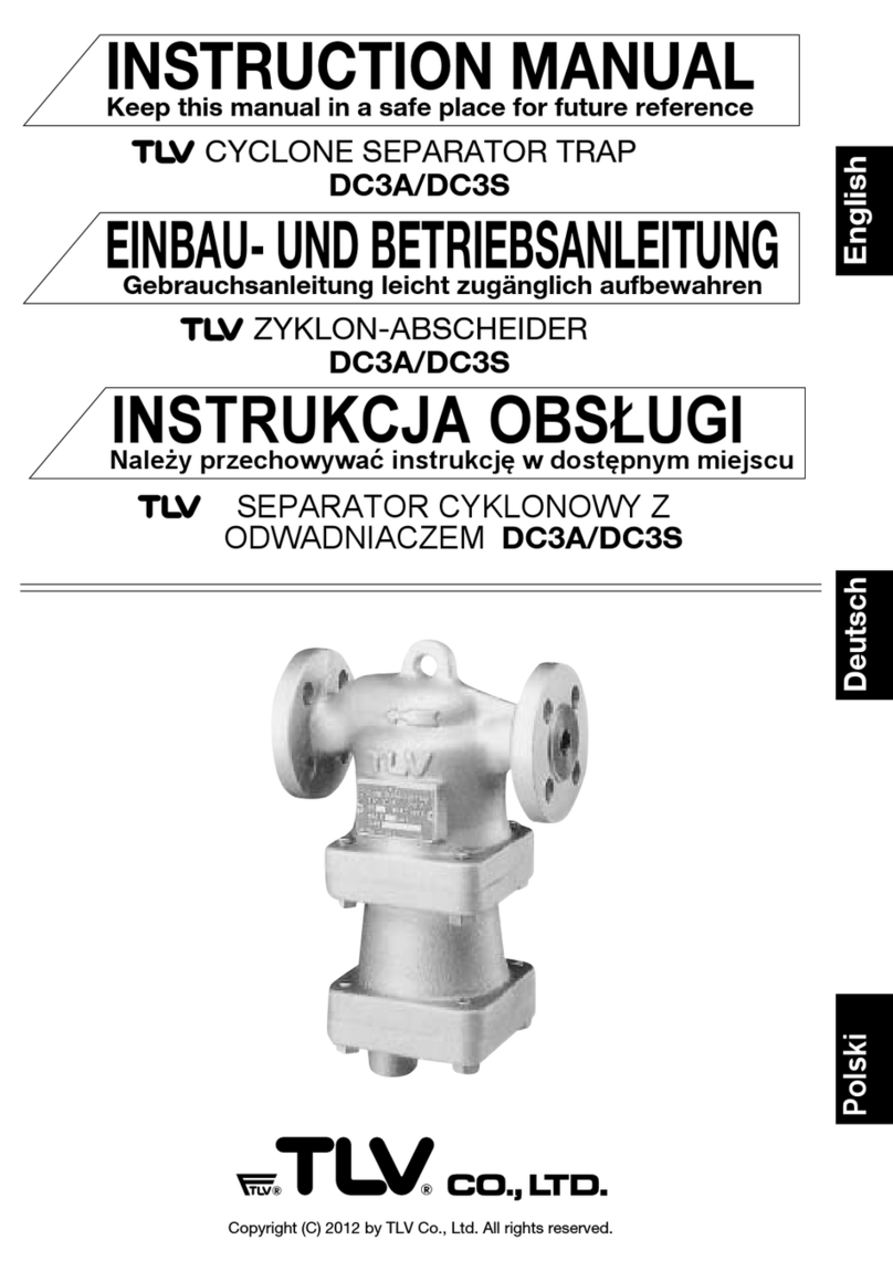
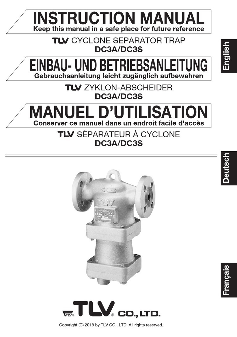
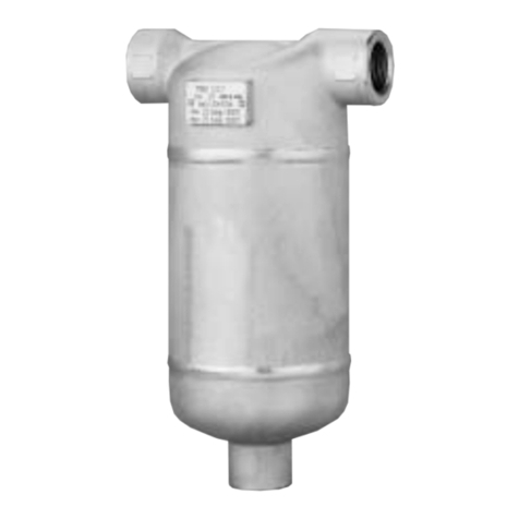
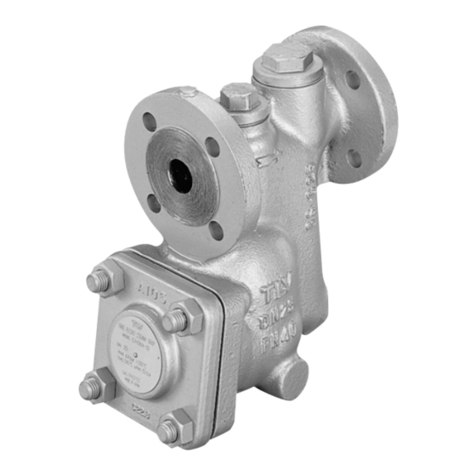
TLV SF1 User manual

Deutsch
Français
English
Separator Filter
MODEL SF1
Trockner-Filter-Einheit
TYP SF1
Filtre séparateur
MODÈLE SF1
SF1
Copyright (C) 2019 by TLV CO., LTD. All rights reserved.
INSTRUCTION MANUAL
EINBAU- UND BETRIEBSANLEITUNG
MANUEL D UTILISATION
Keep this manual in a safe place for future reference
Gebrauchsanleitung leicht zugänglich aufbewahren
Conserver ce manuel dans un endroit facile d'accès

Introduction
Thank you for purchasing the TLV separator filter.
This product has been thoroughly inspected before being shipped from the factory. When the
product is delivered, before doing anything else, check the specifications and external
appearance to make sure nothing is out of the ordinary. Also be sure to read this manual carefully
before use and follow the instructions to be sure of using the product properly.
The SF1 separator filter combines a high-performance filter with a cyclone separator that
removes dirt, scale and condensate (entrained moisture) by means of centrifugal force and
gravity. The SF1 can be used for both separator and filter applications. It is suitable for use in
steam and air mains, and in applications calling for high-quality steam and air.
If detailed instructions for special order specifications or options not contained in this manual are
required, please contact TLV for full details.
This instruction manual is intended for use with the model(s) listed on the front cover. It is
necessary not only for installation, but for subsequent maintenance, disassembly/reassembly and
troubleshooting. Please keep it in a safe place for future reference.
Contents
Introduction………………………………………………....……....……....……............................ 1
Safety Considerations…………………………….....……………......................................... 2
Specifications……………………………………………………………………………….……...... 3
Configuration……………………………………………………………………………….……....... 3
Installation……………………………………………………………………………….…….............
4
Maintenance…………………………………………………........................................................ 8
Disassembly / Reassembly……………..……..........…................................................... 9
Troubleshooting………………………………..………...………...........……………..……....... 11
Product Warranty……………..……..........…...........……………..……..........…...................
11
English
1

English
Do not use excessive force when connecting threaded pipes to the
product.
Over-tightening may cause breakage leading to fluid discharge, which may
cause burns or other injury.
Be sure to use only the recommended components when repairing
the product, and NEVER attempt to modify the product in any way.
Failure to observe these precautions may result in damage to the
product and burns or other injury due to malfunction or the discharge of
fluids.
Use only under conditions in which no freeze-up will occur.
Freezing may damage the product, leading to fluid discharge, which may
cause burns or other injury.
Use only under conditions in which no water hammer will occur.
The impact of water hammer may damage the product, leading to fluid
discharge, which may cause burns or other injury.
2
CAUTION
Install properly and DO NOT use this product outside the recommended
operating pressure, temperature and other specification ranges.
Improper use may result in such hazards as damage to the product or
malfunctions that may lead to serious accidents. Local regulations may
restrict the use of this product to below the conditions quoted.
Make sure the nut on the body clamp is fully tightened.
Failure to do so may result in burns or other injury from the discharge of
fluids.
Use hoisting equipment for heavy objects (weighing approximately
20 kg (44 lb) or more).
Failure to do so may result in back strain or other injury if the object
should fall.
When disassembling or removing the product, wait until the internal
pressure equals atmospheric pressure and the surface of the
product has cooled to room temperature.
Disassembling or removing the product when it is hot or under pressure
may lead to discharge of fluids, causing burns, other injuries or damage.
1. Safety Considerations
• Read this section carefully before use and be sure to follow the instructions.
• Installation, inspection, maintenance, repairs, disassembly, adjustment and valve
opening/closing should be carried out only by trained maintenance personnel.
• The precautions listed in this manual are designed to ensure safety and prevent equipment
damage and personal injury. For situations that may occur as a result of erroneous handling,
three different types of cautionary items are used to indicate the degree of urgency and the
scale of potential damage and danger: DANGER, WARNING and CAUTION.
• The three types of cautionary items above are very important for safety; be sure to observe
all of them, as they relate to installation, use, maintenance, and repair. Furthermore, TLV
accepts no responsibility for any accidents or damage occurring as a result of failure to
observe these precautions.
Indicates a DANGER, WARNING or CAUTION item.

3. Configuration
L
O
T
To avoid malfunctions, product damage, accidents or serious injury,
install properly and DO NOT use this product outside the specification
range. Local regulations may restrict the use of this product to below the
conditions quoted.
CAUTION
2. Specifications
The filter grade (μm) is indicated by numbers at the end of the model name and on the bottom of
the filter.
* Maximum allowable pressure (PMA) and maximum allowable temperature (TMA) are PRESSURE
SHELL DESIGN CONDITIONS, NOT OPERATING CONDITIONS.
** Valve No. is displayed for products with options. This item is omitted from the nameplate when
there are no options.
Refer to the product nameplate for detailed specifications.
Nominal Diameter
Maximum Allowable
Pressure*
Maximum Operating
Pressure
Valve No.**
Model/Filter Grade
Production Lot No.
Maximum Allowable
Temperature (TMA)*
Maximum Operating
Temperature (TMO)
No.
1
2
3
4
5
6
7
8
9
10
11
12
13
Body
Separator
Separator Body
Separator Bottom
Baffle
Filter
Filter Gasket
Body Clamp
Body Gasket
Nameplate
Clamp Bolt
Spring Washer
Clamp Nut
Name
①
⑩
⑧
⑧
②
③
⑥
⑤
④
⑦
⑨
11
12
13
3
English

• Installation, inspection, maintenance, repairs, disassembly, adjustment
and valve opening/closing should be carried out only by trained
maintenance personnel.
• Take measures to prevent people from coming into direct contact with product outlets.
• Install for use under conditions in which no freeze-up will occur.
• Install for use under conditions in which no water hammer will occur.
CAUTION
4. Installation
1. Ensure the filter grade (μm) is correct by checking the numbers at the end of the model name
on the nameplate and on the bottom of the filter.
2. Before installation, be sure to remove all protective seals.
3. Install the separator filter in a location where the removal and filtration of entrained dirt, scale
and condensate would be most effective. (For example, on a main or branch at the inlet of
equipment requiring high-quality dry steam.)
4. Install valves (A) (B) at the inlet and outlet of the separator filter and a piping blowdown
pipe/valve (C) before the inlet valve (A). (See the “Typical Piping Flow” diagram in the “For
Longer Filter Life” section on page 7)
5. Before using the product, close the inlet valve (A), open the piping blowdown valve (C) and
blow out the piping to remove any piping scraps, dirt and oil. Close the piping blowdown
valve (C) when finished. (See the “Typical Piping Flow” diagram in the “For Longer Filter Life”
section on page 7)
6. Install pressure gauges at the separator filter inlet and separator filter outlet or the pressure
detection port in order to monitor the pressure differential.
7. Install the separator filter so the arrow on the body is pointing in the direction of steam or
air flow and the condensate outlet is on the bottom.
8. The product must be installed horizontally and with no more than 10° inclination horizontally
and front-to-back.
Allowable Inclination: 10˚
The product should be installed so that the letters TLV on the body are horizontal.
10˚
10˚
10˚
10˚
4
English

9. Install discharge piping from the condensate discharge port, including a vertical union,
dirt/scale collection piping, piping blowdown valve (C) and horizontal piping with steam, air or
drain trap and an inlet valve (D) for the trap. (See the “Typical Piping Flow” diagram in the “For
Longer Filter Life” section on page 7)
10. Make sure to install a free float trap that discharges condensate continuously during operation
along with separator filter.
11. Close the dirt/scale blowdown valve (E) below the dirt/scale collection piping, open the
separator filter inlet valve (A), outlet valve (B) and the trap inlet valve (D), and ensure that the
separator filter functions properly. (See the “Typical Piping Flow” diagram in the “For Longer
Filter Life” section on page 7)
12. After letting some live steam/air enter the filter, allow the separator filter to cool to ambient
temperature, and then tighten the clamp further.
13. Ensure the maintenance space is sufficient for maintenance (i.e. replacement of internal filter).
If there is a problem, determine the cause using the “Troubleshooting” section of this manual.
NOTE: At start-up, large amounts of initial condensate are generated. Also, during batch
operation, a large amount of condensate may accumulate in the piping when
operation stops. If there are concerns that a large amount of condensate could flow
into the separator filter, make sure to install a piping blowdown valve at the inlet of
the separator filter to ensure that the condensate is eliminated, or install a steam
trap with sufficient discharge capacity even when the pressure differential is
extremely low. (See “For Longer Filter Life” items 1, 2 and 3)
SF1 Connection Size
mm
15 - 40mm
50mm
SS1 Series, J3S-X, J3X
JH5SL, J5S-X, J5X
For Steam Use
JA3, JA3D, SS1VG Series
JA5, JAH5RG Series
For Air Use
(in)
( -1 )
(2)
2
1
/
2
1
/
SF1 Connection Size Min. Maintenance Space (S)
mm
15, 20
25
40
50
100
150
300
350
(4)
(6)
(12)
(14)
(in) mm (in)
( - )
(1)
(1 )
(2)
2
1
/
2
1
/
4
3
/
Example
S
English

For Longer Filter Life
Make sure to perform the following to prevent the inflow of a large amount of condensate during
start-up. (See the “Typical Piping Flow” diagram below)
1. Operate inlet valve (A) being careful not to open it quickly.
2. If the condensate accumulates when inlet valve (A) is closed, open piping blowdown valve (C)
to blow it out.
3. If a blowdown valve has not been installed, a steam trap with sufficient discharge capacity
even when the pressure differential is extremely low must be installed on the separator filter
inlet side considering the initial condensate amount.
4. The trap outlet piping should not be located close to other trap outlet piping or backflow may
occur. If other outlet piping is close by, install check valves close to each trap outlet.
5. If the trap outlet piping is raised, install a check valve close to the trap outlet to prevent
backflow of condensate when the equipment stops.
6. Trap outlet pipe end should not be under water. If it needs to be under water, install a check
valve close to the trap outlet or make a small hole in the outlet piping to prevent backflow of
water due to vacuum formation inside the piping.
Typical Piping Flow
Ahead of the inlet
valve for the SF1,
install a valve for
piping blowdown or
a steam trap with
sufficient discharge
capacity when
differential pressure
is extremely low.
Pressure
Gauge
Dirt & Scale
Collection
Union
Valve
Pressure
Gauge
(hot/cold water,
steam or air)
Washing
Dirt & Scale Blowdown
Piping Blowdown/
Condensate Discharge
Outlet Valve
(B)
Valve
(D)
Trap
Valve
(C)
Valve
(E)
Inlet Valve
(A)
English

To Minimize Pressure Loss Effects
Pressure loss across the separator filter increases the longer it is in service, resulting in a
continuous decrease in secondary pressure. If a slight drop in secondary pressure will
affect the process, refer to the "In cases where more stable pressure is needed" piping flow
diagram shown below.
The effects of gradually increasing pressure loss can be minimized. However, this does not
mean that the service life of the clogging filter can be prolonged.
In cases where more stable pressure is needed
*If a pressure reducing valve other than COSPECT (with built-in strainer, separator, and
steam trap) is installed, the equipment indicated by A in the diagram on the previous
page must be installed ahead of the pressure reducing valve for the SF1 inlet.
** If it becomes impossible to adjust the pressure with the pressure reducing valve due to
build-up of dirt/scale, clean or replace the filter.
lnstalling a COSPECT
pressure reducing valve*
with an external pressure
sensing line from the outlet
of the SF1 will help supply
stable pressure and
minimize pressure drop,
which gradually increases
due tobuild-up of dirt/scale
at the filter.
Dirt & scale build-up,
SF1outlet pressure
dorops.
Pressure reducing valve
detects pressure drop
and automatically
increases SF1 inlet
pressure.
SF1 outlet pressure
rises to maintain set
pressure.**
Pressure
Gauge
Pressure
Gauge
Pressure
Gauge
Dirt & Scale
Collection
Pressure
Reducing
Valve
Condensate
Discharge
COSPECT Union
Valve
Valve
Valve
Valve
Valve
(hot/cold water,
steam or air)
Dirt & Scale Blowdown
Washing
Outlet Valve
Steam Trap
Inlet Valve
Secondary
Pressure
Sensing Line
①
②
③
①
②③
English
7

5. Maintenance
Operational Check
Make sure that there is sufficient steam or air flow from the separator filter outlet by checking the
difference in inlet and outlet pressures (pressure loss) or any available flow meters. If the
differential pressure is too large (pressure loss is several times more than when the product was
new) or there is too little flow, the filter may be clogged. Disassemble, inspect and clean the filter,
or replace as necessary.
Filter Cleaning & Replacement
When cleaning is required, first use back flow cleaning by supplying hot or cold water, steam, or
air through the washing port on the top of the separator filter (details below). When the clogging
is more severe, disassemble and apply high-pressure water cleaning, ultrasonic cleaning, acid
cleaning, or other appropriate method directly to the filter. Replace with a new filter when
cleaning is ineffective. We recommend having spare filters on hand for this purpose.
Valve Status during Backwash
Pressure Gauge Pressure Gauge
Inlet valve is closed Outlet valve is closed
Union Trap inlet valve is closed
Blowdown valve is
open
Trap
Dirt/scale
collection
Hot or cold
water,
steam,
or air
(valve open)
• Installation, inspection, maintenance, repairs, disassembly, adjustment
and valve opening/closing should be carried out only by trained
maintenance personnel.
• Before attempting to open the separator, close the inlet and outlet isolation valves and wait
until the product has cooled completely. Failure to do so may result in burns.
• Be sure to use the proper components and NEVER attempt to modify the product.
CAUTION
English
8

Use the following procedures to remove components. Use the same procedures in reverse to
reassemble. (Installation, inspection, maintenance, repairs, disassembly and adjustment should
be carried out only by trained maintenance personnel.)
6. Disassembly/Reassembly
Removing/Reattaching the Separator Body and its Components
Part Disassembly Reassembly
Reassembly
Body Clamp
Body /
Separator
Body
Body Gasket
Hold the separator body
so that it will not fall;
loosen the nut.
Remove the clamp and
pull the separator body
down and off, being
careful not to scratch the
gasket sealing surfaces.
Be careful not to scratch
the sealing surfaces.
Insert the clamp bolt from the side which has a rotation
stopper.
Consult the table of tightening torques and tighten the nut
to the proper torque so that there is no seal leakage.
Open the inlet valve and let live steam/air to enter the filter,
then close the inlet valve; after internal and atmospheric
pressures have equalized and the separator filter body has
cooled, tighten nut again.
Gently rejoin being careful to insert the raised part of
the body gasket into the housing on the body.
Reattach the body clamp.
Replace with a new gasket if warped or damaged.
Place on the separator body.
Disassembly/Reassembly of the Filter
Part Disassembly
Filter
Separator
Filter Gasket
Remove with a wrench
NOTE:
The separator comes off
with the filter. Make sure
not to drop the separator.
Remove the separator;
clean sealing surface on
the separator and body.
Be careful not to scratch
the surface.
Check for dents and damage, etc. to both threads in
order to prevent seizing, and clean the threads by
blowing them out with air. Then manually screw the
filter into the body carefully until it hits the bottom.
Next, consult the table of tightening torques and
tighten to the proper torque.
Coat thread portions with a small amount of food
grade anti-seize (such as “NEVER-SEEZ PTFE White
Food Grade” made by Bostik, Inc.). Avoid using too
much as anti-seize may ooze out of the thread.
Assemble the separator onto the body together with
the filter
Replace with a new gasket if warped or damaged
English
9

Table of Tightening Torques
NOTE: If drawings or other special documentation were supplied for the product, any torque
given there takes precedence over values shown here.
Part
mm
15, 20
25
40
50
15, 20
25
40
50
N·m
30
40
50
60
15
20
25
50
(lbf·ft)
(22)
(29)
(37)
(44)
(11)
(15)
(18)
(37)
mm
32
36
50
60
Clamp Bolt
: 14 ( )
Clamp Nut
: 16 ( )
(in)
(1 )
(1 )
( 2 )
(2 )
(in)
( , )
( 1 )
(1 )
( 2 )
( , )
( 1 )
(1 )
( 2 )
SF1
Connection Size Distance
Across Flats
Torque
Body
Clamp
(nut)
Filter
2
1
/
2
1
/
4
1
/
8
3
/
16
7
/
16
9
/
8
5
/
2
1
/
4
3
/
2
1
/
4
3
/
1 N·m ≈10 kg·cm
Exploded View
Body
Body Clamp
Rotation Stopper
Rotation Stopper
Clamp Bolt
Separator
Filter Gasket
Filter
Clamp Nut
Spring Washer
Body Gasket
Separator Body
English

If the product fails to operate properly, use the following table to locate the cause and remedy.
7. Troubleshooting
Problem
Matter larger than the
specified filter grade passes
through the separator outlet
Outlet side steam or air
retains entrained condensate
The outlet pressure is too low
or the specified flow rate
cannot be achieved
The filter grade is incorrect
The filter is broken
Steam or air is leaking
between the body and
separator body
The installation is incorrect Correct the installation
Clean the filter or replace with
new
Replace with a new gasket
Tighten the nut to the proper
torque
The flow rate is too high or
flow velocity is too fast for the
separator filter
The pressure loss through the
filter is too large
The filter is clogged
The nut on the clamp is not
fully tightened
There is gasket deterioration
or damage
Replace with a new filter
Make corrections to the piping
to reduce flow rate and
velocity
Replace with a filter with the
correct grade
Cause Remedy
1. Warranty Period
One year following product delivery.
2. Warranty Coverage
TLV CO., LTD. warrants this product to the original purchaser to be free from defective
materials and workmanship. Under this warranty, the product will be repaired or replaced at
our option, without charge for parts or labor.
3. This product warranty will not apply to cosmetic defects, nor to any product whose exterior has
been damaged or defaced; nor does it apply in the following cases:
1) Malfunctions due to improper installation, use, handling, etc., by other than TLV CO., LTD.
authorized service representatives.
2) Malfunctions due to dirt, scale, rust, etc.
3) Malfunctions due to improper disassembly and reassembly, or inadequate inspection and
maintenance by other than TLV CO., LTD. authorized service representatives.
4) Malfunctions due to disasters or forces of nature.
5) Accidents or malfunctions due to any other cause beyond the control of TLV CO., LTD.
4. Under no circumstances will TLV CO., LTD. be liable for consequential economic loss damage
or consequential damage to property.
8. Product Warranty
English
11

Inhaltsverzeichnis
Vorwort………………………………………………....……....……....…….................................... 12
Sicherheitshinweise…………………………….....……………............................................ 13
Technische Daten…………………………………………………………………...….....…...... 14
Aufbau……………………………………………………………………………….…….................... 14
Installationshinweise…………………………………………………….....…….……............. 15
Wartung…………………………………………………................................................................. 19
Ausbau & Einbau……………..……..........…........................................................................ 20
Fehlersuche………………………………..………...………...........…………..........…..……...... 22
Garantie……………..……..........…...........……………..……..........…........................................ 22
Vorwort
Wir danken Ihnen für den Kauf unserer TLV Trockner-Filter-Einheit.
Dieses Produkt wurde nach Fertigstellung sorgfältig geprüft und verließ unsere Fabrik vollständig
und fehlerfrei. Wir empfehlen Ihnen jedoch, gleich nach Erhalt den einwandfreien Zustand visuell
zu überprüfen und die Spezifikation mit Ihren Bestellunterlagen zu vergleichen. Sollten Sie dabei
Abweichungen von der Spezifikation oder sonstige Fehler feststellen, bitten wir Sie, uns
umgehend zu benachrichtigen.
Die SF1 Trockner-Filter-Einheit verbindet einen Hochleistungsfilter mit einem Zyklon-Abscheider,
der Verschmutzungen, Ablagerungen und Kondensat mittels Zentrifugal- und Gravitationskräften
abscheidet. Die Einheit kann sowohl zur Anwendung als Abscheider, als auch als Filter benutzt
werden. Sie ist für den Einsatz in Anlagen mit Dampf oder Druckluft ebenso geeignet, wie für
Anwendungen, die eine hochwertige Dampf- bzw. Druckluftqualität erfordern.
Wenden Sie sich bitte an TLV für Optionen oder Sonderausführungen, die nicht in dieser Einbau-
und Betriebsanleitung enthalten sind.
Diese Anleitung kann nur für Installation, Betrieb, Wartung, sowie Ausbau und Zusammenbau der
auf der Vorderseite angegebenen Typen benutzt werden. Wir empfehlen, vor Einbau und
Inbetriebnahme die Anleitung sorgfältig durchzulesen und an einem leicht zugänglichen Platz
aufzubewahren.
12
Deutsch

VORSICHT
Die Einbauhinweise beachten und die spezifizierten Betriebsgrenzen NICHT
ÜBERSCHREITEN.
Nichtbeachtung kann zu Betriebsstörungen oder Unfällen führen.
Lokale Vorschriften können zur Unterschreitung der angegebenen Werte zwingen.
Die Schraubmutter auf dem Gehäuse-Clamp muss vollständig
angezogen sein.
Nichtbeachtung kann zu Verbrennungen und anderen Verletzungen
durch austretende Fluide führen.
Für schwere Werkstücke (ca. 20 kg oder mehr) werden
Hebezeuge dringend empfohlen.
Nichtbeachtung kann zu Rückenverletzungen oder Verletzungen durch
das herunterfallende Werkstück führen.
Vor Öffnen des Gehäuses und Ausbau von Teilen warten, bis
der Innendruck sich auf Atmosphärendruck gesenkt hat und
das Gehäuse auf Raumtemperatur abgekühlt ist.
Nichtbeachtung kann zu Verbrennungen oder Verletzungen durch
austretende Fluide führen.
Bei Schraubanschlüssen keine übermäßige Kraft anwenden, um die
Gewinde nicht zu beschädigen.
Lecks wegen Gewindeschäden können zu Verbrennungen oder
Verletzungen durch austretende Fluide führen.
Zur Reparatur nur Original-Ersatzteile verwenden und NICHT
VERSUCHEN, das Produkt zu verändern.
Nichtbeachtung kann zu Beschädigungen führen, die Betriebsstörungen,
Verbrennungen oder Verletzungen durch austretende Fluide verursachen.
Nur in frostsicherer Umgebung einsetzen.
Einfrieren kann das Produkt beschädigen, was zu Verbrennungen oder
Verletzungen durch austretende Fluide führt.
Nur an Stellen einbauen, an denen kein Wasserschlag eintreten
kann. Wasserschlag kann das Produkt beschädigen und zu Verbren-
nungen oder Verletzungen durch austretende Fluide führen.
1. Sicherheitshinweise
• Bitte lesen Sie dieses Kapitel vor Beginn der Arbeiten sorgfältig durch und befolgen Sie die Vorschriften.
• Einbau und Ausbau, Inspektion, Wartungs- und Reparaturarbeiten, Öffnen/Schließen von Armaturen,
Einstellung von Komponenten, dürfen nur von geschultem Wartungspersonal vorgenommen werden.
• Die Sicherheitshinweise in dieser Einbau- und Betriebsanleitung dienen dazu, Unfälle, Verletzungen,
Betriebsstörungen und Beschädigungen der Anlagen zu vermeiden. Für Gefahrensituationen, die durch
falsches Handeln entstehen können, werden drei verschiedene Warnzeichen benutzt: GEFAHR;
WARNUNG; VORSICHT.
• Diese drei Warnzeichen sind wichtig für Ihre Sicherheit. Sie müssen unbedingt beachtet werden, um den
sicheren Gebrauch des Produktes zu gewährleisten und Einbau, Wartung und Reparatur ohne Unfälle
oder Schäden durchführen zu können. TLV haftet nicht für Unfälle oder Schäden, die durch
Nichtbeachtung dieser Sicherheitshinweise entstehen.
bedeutet, dass die Möglichkeit der Gefahr für Leib und Leben besteht.
WARNUNG
bedeutet, dass eine unmittelbare Gefahr für Leib und Leben besteht.
GEFAHR
VORSICHT
bedeutet dass die Möglichkeit von Verletzungen oder Schäden an
Anlagen oder Produkten besteht.
Dieses Zeichen weist auf GEFAHR; WARNUNG; VORSICHT hin.
13
Deutsch

2. Technische Daten
VORSICHT
Die Einbauhinweise beachten und die spezifizierten Betriebsgrenzen
NICHT ÜBERSCHREITEN.
Nichtbeachtung kann zu Betriebsstörungen oder Unfällen führen. Lokale
Vorschriften können zur Unterschreitung der angegebenen Werte
zwingen.
3. Aufbau
Nr.
1
2
3
4
5
6
7
8
9
10
11
12
13
Gehäuse
Zyklonabscheider
Abscheidergehäuse
Abscheiderboden
Prallplatte
Filter
Filterdichtung
Gehäuseklammer
Gehäusedichtung
Typenschild
Gehäuseklammer-Schraube
Unterlegscheibe
Gehäuseklammer-Mutter
Name
Die verwendete Filterfeinheit (μm) wird durch Zahlen hinter der Typenbezeichnung und an der
Filterunterseite angegeben.
* Maximal zulässiger Druck (PMA) und maximal zulässige Temperatur (TMA) sind
AUSLEGUNGSDATEN, NICHT BETRIEBSDATEN.
** Die “Ventil-Nr.” wird angegeben bei Typen mit Optionen. Bei Typen ohne Optionen bleibt
diese Stelle frei.
Die technischen Daten stehen auf dem Typenschild.
Größe/DN
maximal
zulässiger Druck*
maximaler
Betriebsdruck
Ventil-Nr.**
Typ/Filterfeinheit
Fertigungslos-Nr.
maximal zulässige
Temperatur (TMA)*
maximale
Betriebstemperatur (TMO)
①
⑩
⑧
⑧
②
③
⑥
⑤
④
⑦
⑨
11
12
13
L
O
T
14
Deutsch

4. Installationshinweise
1. Versichern Sie sich, dass die Filterfeinheit (μm) korrekt ist, indem Sie die Zahlen am Ende der
Typenbezeichnung auf dem Typenschild oder an der Filterunterseite überprüfen.
2. Vor Einbau alle Verschlusskappen entfernen.
3. Bauen Sie die Trockner-Filter-Einheit an geeigneter Stelle ein, an der die Abscheidung von
Schmutz, Leitungsabrieb und Kondensat am wirkungsvollsten ist (z.B. in eine Zuleitung, an
einen Abzweig, oder an den Eintritt eines Dampfverbrauchers, der trockenen, gefilterten
Dampf benötigt).
4. Vor dem Ein- und hinter dem Auslass der Trockner-Filter-Einheit ist jeweils der Einbau eines
Absperrorgans (A) (B) („Einlass-/Auslassventil“) erforderlich, ebenso ein Ausblaseventil (C) vor
dem Absperrorgan (A) am Eintritt (siehe Zeichnung im folgenden Abschnitt “Lange Filter-
Lebensdauer” auf Seite 21).
5. Vor Inbetriebnahme das Absperrorgan (A) am Eintritt schließen, das Ausblaseventil (C) öffnen
und Schmutz, Leitungsabrieb oder Öl ablassen. Danach das Ausblaseventil (C) schließen
(siehe Zeichnung im folgenden Abschnitt “Lange Filter-Lebensdauer” auf Seite 21).
6. Vor Ein- und nach Austritt der Trockner-Filter-Einheit, oder an deren Anschlüssen zur
Druckmessung, Manometer zur Kontrolle des Differenzdrucks einbauen.
7. Die Trockner-Filter-Einheit so installieren, dass der Pfeil auf dem Gehäuse in
Strömungsrichtung zeigt und der Kondensatauslass unten ist.
8. Die Trockner-Filter-Einheit muss waagerecht eingebaut werden, mit einer maximalen Neigung
von 10° um Längs-/Querachse.
10˚
10˚
10˚
10˚
Toleranzwinkel bei der Installation: 10˚
Nach sachgemäßer Installation steht der Schriftzug TLV auf dem Gehäuse horizontal.
VORSICHT
• Einbau und Ausbau, Inspektion, Wartungs- und Reparaturarbeiten,
Öffnen/Schließen von Armaturen, Einstellung von Komponenten, dürfen
nur von geschultem Wartungspersonal vorgenommen werden.
• In sicherer Enfernung von Auslassöffnungen aufhalten und andere Personen warnen, sich fern
zu halten.
• Trockner-Filter-Einheit in frostsicherer Umgebung einbauen .
• Trockner-Filter-Einheit nur dort einbauen, an denen kein Wasserschlag eintreten kann.
15
Deutsch

9. Schließen Sie über eine vertikale Rohrverschraubung eine Auslassleitung an den
Kondesatauslassstutzen an, eine Sammelleitung für Schmutz und Leitungsabrieb, ein
Ausblaseventil (C) und einen Kondensatableiter mit einem eingangseitigen Absperrorgan (D) in
der horizontalen Leitung (siehe Zeichnung im folgenden Abschnitt “Lange Filter-Lebensdauer”
auf Seite 21).
10. Installieren Sie an der Trockner-Filter-Einheit einen Frei-Schwimmer-Kondensatableiter für
kontinuierlichen, gleichmäßigen Kondensataustrag.
11. Schließen Sie das Absperrorgan (E) unter der Sammelleitung für Schmutz und Leitungsabrieb,
öffnen Sie die Absperrorgane am Eintritt (A) und am Auslass (B) der Trockner-Filter-Einheit
sowie das Absperrorgan (D) vor dem Kondesatableiter und vergewissern Sie sich, dass die
Trockner-Filter-Einheit einwandfrei funktioniert (siehe Zeichnung im folgenden Abschnitt
“Lange Filter-Lebensdauer” auf Seite 21).
12. Leiten Sie Sattdampf in die Trockner-Filter-Einheit, lassen Sie sie anschließend wieder auf
Umgebungstemperatur abkühlen und ziehen dann die Gehäuseklammer nach.
13. Stellen Sie sicher, dass ausreichend Platz für Wartungsarbeiten wie Filterwechsel zur
Verfügung steht.
Zur Ursachenbestimmung bei Problemen siehe “Fehlersuche„.
Hinweis: Beim Anfahren fallen größere Mengen Kondensat an; ebenso laufen im
Sammelbetrieb bei Betriebsunterbrechungen größere Mengen Kondensat in der
Leitung auf. Um sicherzustellen, dass keine größeren Mengen Kondensat in die
Trockner-Filter-Einheit einlaufen, ist in diesen Fällen an der Einlassseite der
Trockner-Filter-Einheit die Installation eines Ausblaseventils oder eines
ausreichend dimensionierten Kondensatableiters für besonders niedrigen
Differenzdruck empfehlenswert. (siehe folgenden Abschnitt "Lange Filter-
Lebensdauer", Punkte 1, 2 und 3.)
SF1 Größe/DN
15-40
50
Serie SS1; J3S-X, J3X
JH5SL, J5S-X, J5X
Dampfanwendungen
Serien JA3, JA3D, SS1VG
Serien JA5, JAH5RG
Druckluftanwendungen
SF1 Größe/DN Für Wartung erforderliche
Mindestabstände S (mm)
15, 20
25
40
50
100
150
300
350
Beispiele
S
Deutsch
16

Lange Filter-Lebensdauer
Befolgen Sie bitte folgende Schritte, um den Eintritt größerer Mengen Kondensats in die
Trockner-Filter-Einheit zu vermeiden. (siehe Zeichnung unten)
1. Das Absperrorgan (A) an der Einlassseite langsam öffnen.
2. Falls sich bei geschlossenem Einlassventil (A) Kondensat aufstaut, Ausblaseventil (C) öffnen
und ausblasen.
3. Falls kein Ausblaseventil installiert wurde, muss an der Einlassseite der Trockner-Filter-Einheit
ein Kondensatableiter mit ausreichender Durchsatzkapazität auch bei besonders niedrigem
Differenzdruck angebracht werden, wobei der gesteigerte Kondensatanfall beim Anfahren der
Anlage zu beachten ist.
4. Zur Vermeidung von Rückstau sollte der Auslass des Kondensatableiters nicht nahe eines
anderen Auslasses installiert werden. Lässt sich dies nicht vermeiden, muss hinter jedem
Ableiter ein Rückschlagventil angebracht werden.
5. Ist die Verrohrung des Kondensatableiter-Auslasses ansteigend, ein Rückschlagventil nahe
am Auslass installieren, um Kondensatrückfluss bei Betriebsunterbrechungen zu verhindern.
6. Das Leitungsende des Kondensatableiter-Auslasses sollte nicht ein Auffangbecken
eintauchen. Falls das Leitungsende eintauchen soll, muss am Kondensatableiter-Auslass ein
Rückschlagventil installiert oder in die Auslassleitung eine kleine Lüftungsbohrung eingebracht
werden, um Kondensatrückfluss bei Vakuumbildung zu verhindern.
Typische LeitungsausIegung
Ausblaseventil vor
Absperrventil am
Eintritt, oder KA mit
ausreichender
Durchsatzkapazität
auch bei besonders
niedrigem Differenz-
druck installieren.
Manometer Manometer
Sammelleitung
für Schmutz und
Leitungsabrieb
Union
Absperrventil
(heißes/kaltes Wasser,
Dampf oder Druckluft)
Rückspülung
Ausblaseleitung
Leitungsausblasen/
Kondensataustrag
Auslassventil
(B)
Ventil
(D) Kondensatableiter
Ventil
(C)
Ventil
(E)
Einlassventil
(A)
17
Deutsch

Zur Druckverlust-Minimierung
Der Druckverlust bei Durchströmung des Filter-Trockners erhöht sich mit zunehmender
Betriebszeit, sodass der Druck auf der Auslassseite mit fortschreitender Betriebszeit
kontinuierlich abnimmt. Für Anwendungen, bei denen auch kleine Druckminderungen
signifikante Auswirkungen auf den Anwendungsprozess haben, stellt das unten abgebildete
Strömungsdiagramm „Bei Bedarf an besonders stabilem Dampfdruck“ eine Lösung dar.
Hiermit kann fortschreitender Druckverlust minimiert werden. Diese Maßnahme verlängert
nicht die Brauchbarkeitsdauer des allmählich verstopfenden Filters.
Bei Bedarf an besonders stabilem Dampfdruck
*Bei Installation eines Druckminderventils, das nicht wie COSPECT über ein eingebautes
Schmutzsieb, einen Abscheider und einen Kondensatableiter verfügt, muss die mit A
bezeichnete Armatur im Diagramm auf der vorhergehenden Seite vor dem
Druckminderventil für SF1 installiert werden.
** Wenn aufgrund von übermäßiger Schmutzansammlung oder Ablagerungen der Druck
auch mit Hilfe des Druckminderventils nicht mehr bereitgestellt werden kann, den Filter
reinigen oder austauschen.
Die installation eines
COSPECT Druckminder-
ventils* mit externer Steuer-
leitung zum Auslass des SF1
stabilisiert den Druck und
minimiert den allmählich fort-
schreitenden Druckverlust
infolge von Verschmutzung/
Ablagerungen.
Fortschreitende Verschmut-
zung/Ablagerungen, Druck-
minderung auf der SF1-
Auslassseite
Druckminderventil erkennt
Druckminderung und erhöht
automatisch den Druck auf
der SF1-Einlassseite
Der Druck auf der Auslass-
seite des SF1 erhöht sich
auf den eingestellten Wert**
Manometer Manometer
Manometer
Druckminder-
ventil
Kondensataustrag
COSPECT
Ventil
Ventil
Ventil
Ventil Ausblaseleitung
Auslassventil
Kondensatableiter
Einlassventil
Rohrverschraubung
Minderdruck-
Steuerleitung
①
②
③
(heißes/kaltes Wasser,
Dampf oder Druckluft)
Rückspülung
Sammelleitung
für Schmutz und
Leitungsabrieb
①
②③
Deutsch
18

5. Wartung
Funktionsprüfung
Stellen Sie sicher, dass ein ausreichend starker Durchfluss durch die Trockner-Filter-Einheit
gewährleistet ist: Überprüfen Sie dazu den Druckverlust über die Einheit (Differenz zwischen Vor-
und Gegendruck) oder kontrollieren Sie evtl. verfügbare Durchflussmesser. Zu großer
Druckverlust (ein mehrfaches im Vergleich zum fabrikneuen Zustand) und ungenügender
Durchfluss können von einer Filterverstopfung herrühren. Öffnen, überprüfen und reinigen, ggf.
ersetzen, Sie den Filter.
Filterreinigung und -austausch
Wenn der Filter gereinigt werden muss, ist die Rückspülung mit heißem oder kaltem Wasser,
Dampf oder Luft durch den Reinigungseinlass an der Oberseite der Trockner-Filter-Einheit die
nächstliegende Reinigungsmethode (siehe Zeichnung unten). Bei hartnäckiger Verstopfung muss
der Filter ausgebaut und per Hochdruckwasserstrahl, Ultraschallbad, Säurebad oder anderen
Reinigungsverfahren gesäubert werden. Stellt sich keine Verbesserung ein, muss der Filter ersetzt
werden. Zu diesem Zweck empfiehlt sich ein Vorrat an Ersatzfiltern.
Ventilstellung bei Rückspülung
Manometer Manometer
Einlassventil geschlossen Auslassventil geschlossen
Rohrverschraubung Absperrorgan geschlossen
Ausblaseventil offen
Kondensatableiter
Sammelleitung
für Schmutz
und
Leitungsabrieb
Zufuhr von heißem oder kaltem Wasser,
Dampf oder Luft
VORSICHT
• Einbau und Ausbau, Inspektion, Wartungs- und Reparaturarbeiten,
Öffnen/Schließen von Armaturen, Einstellung von Komponenten dürfen
nur von geschultem Wartungspersonal vorgenommen werden.
• Vor dem Öffnen der Trockner-Filter-Einheit sind die Absperrarmaturen auf beiden Seiten zu
schließen. Gehäuse auf Raumtemperatur abkühlen lassen. Nichtbeachtung kann zu
Verbrennungen führen.
• Zur Reparatur nur Original-Ersatzteile verwenden und NICHT VERSUCHEN, das Produkt zu
verändern.
19
Deutsch
Other manuals for SF1
1
Table of contents
Languages:
Other TLV Water Filtration System manuals
Popular Water Filtration System manuals by other brands
Astrapool
Astrapool E25 Installation and operating instructions
Pulsotronic
Pulsotronic MESEP VA digital 50 manual
Eaton
Eaton PSFi Series operating guide
Bestway
Bestway Flowclear 58397 owner's manual
Graf
Graf EcoPure 200 Instructions for installing and maintaining
BWT
BWT bestaqua 14 Fitting and operating instructions
Alpine
Alpine PLUV10800 quick guide
UV Pure Technologies
UV Pure Technologies Hallett 15xs instruction manual
Aeware
Aeware 0605-500002 user manual
Hayward
Hayward HCF Series Installation and operation manual
Weller
Weller Zero Smog TL Translation of the original instructions
Blanco
Blanco EVOL Mono Hot & Filter HD manual
