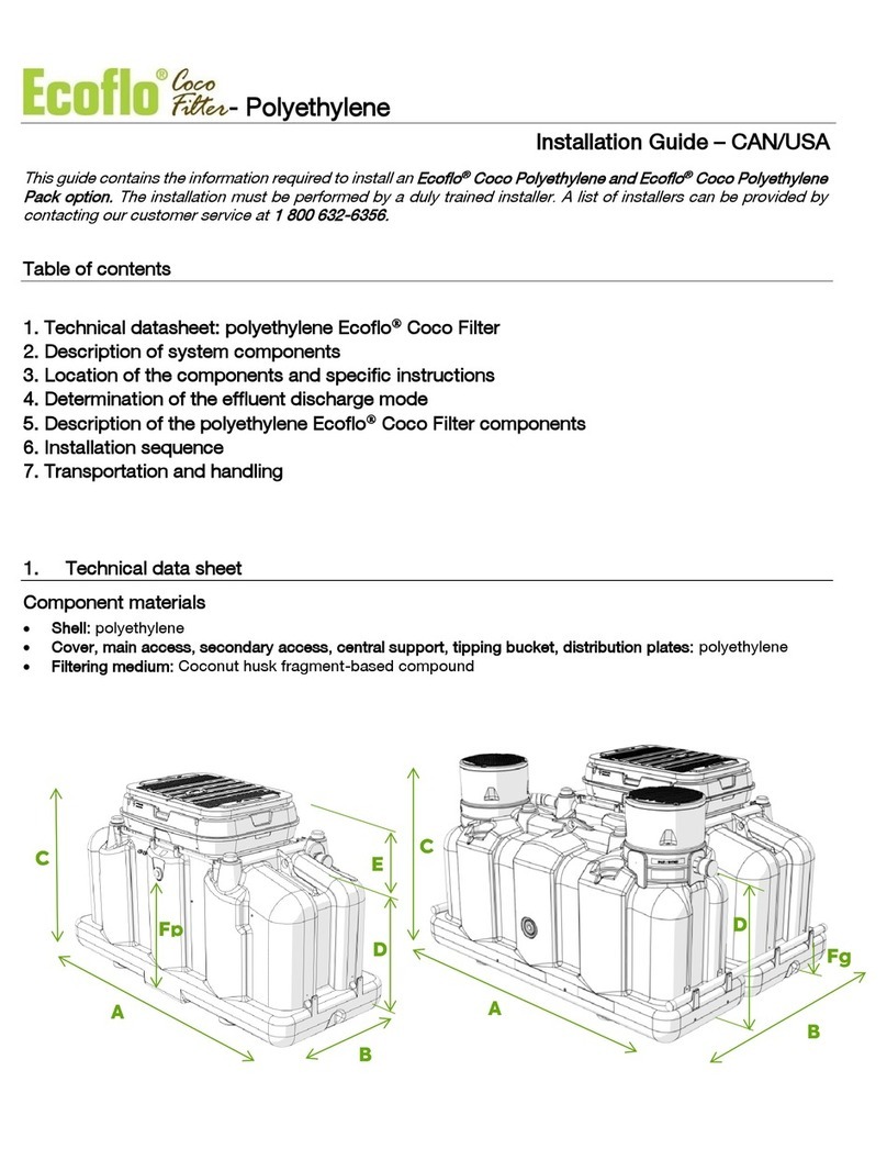
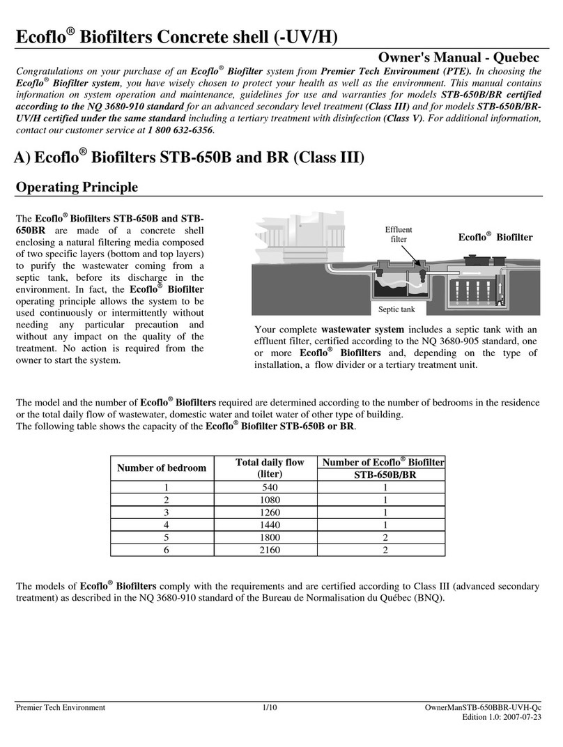
Ecoflo CLIVUS MULTRUM LOW PROFILE User manual

CLIVUS MULTRUM
LOW PROFILE
INSTALLATION & OPERATION MANUAL
IMCM-203-2023.04.18
©Ecoo Wastewater Management Pty Ltd

TABLE OF CONTENTS
ITEMS REQUIRED (NOT INCLUDED) 1
TOOLS REQUIRED 1
SCHEMATICS 2
INSTALLATION 3
STEP 1: POSITION THE PEDESTAL 3
STEP 2: POSITION THE WASTE CHUTE 3
STEP 3: INSTALL THE WASTE CHUTE 5
EXTRA LENGTH FOR UNDER-FLOOR AREAS 6
STEP 4: INSTALL THE WHEELS 7
STEP 5: INSTALL THE MIXER 7
STEP 6: INSTALL THE CHAMBER 8
STEP 7: CONNECT THE VENT PIPE AND FAN 9
OPTIONAL EXTRAS 9
STEP 8: CONNECT THE FLEXIBLE VENT PIPE AND LIQUID DRAIN HOSE 10
POWERING YOUR FAN 11
LEACHATE DRAIN 12
COMPOSTING ACCELERATORS 13
MAINTENANCE 14
ROTATION OF CHAMBERS 15
TROUBLESHOOTING 16
PRODUCT & COMPONENT WARRANTY 18
MAINTENANCE SCHEDULE 19

©Ecoo Wastewater Management Pty LtdIMCM-203-2023.04.18 Page 1
ITEMS REQUIRED (NOT INCLUDED)
Please check the packing slip to ensure everything has been delivered. If anything is missing, please
notify Ecoo within 72 hrs of receipt.
You will need the following items to complete your installation.
Vent items
• Wall brackets to x the vent pipe to the building
• A length of 100mm DWV vent pipe to connect to the air exhaust (length depends on specic
installation)
• Dektite if DWV vent pipe will penetrate the roof
Leachate drain items (please check with your local authority)
• Ø100mm Agricultural pipe
• 1.5m x 0.5m Synthetic or Hessian geotextile mat
• 50mm PVC pipe to connect the hose to the agricultural pipe
• 0.30m³ 20mm Aggregate
A vent kit and drain kit are available to purchase separately from Ecoo.
TOOLS REQUIRED
PVC
CEMENT
SILICONE
Marker Tape Measure Shovel Hand Saw
JigsawPlumb BobPVC CementCaulk Gun
Power Drill Philips Drill Bit Masonry and Brad
Point Drill Bits Hole Saw
Drill Bit

©Ecoo Wastewater Management Pty LtdIMCM-203-2023.04.18 Page 2
Pedestal
Chute
Min. 500mm
Fan in housing
Y Juntion
L.I.T Reducer
Vent pipe
Brackets*
100mm DWV pipe*
45° bend
Dektite*
600mm
600mm
Vent cowl
Camlock fittings
Excess liquid drain hose
T-piece*
(3 way hose connector)
Leachate drain*
Out-of-service
chamber
In-service
chamber
Pedestal
Chute
Min. 500mm
Fan in housing
L.I.T Reducer
Vent pipe
Brackets*
100mm Sewer pipe*
45° bend
Dektite*
600mm
600mm
Vent cowl
Camlock fittings
Excess liquid drain hose
Leachate drain*
In-service
chamber Out-of-service
chamber
SCHEMATICS
If you are planning
to excavate an area
under the house for
the compost chambers,
please ensure the area
is well-drained and any
retaining walls are built
to the satisfaction of
the local authority.
Optional Vent
Installation
Optional Installation An optional extra connection
kit is available to purchase
separately from Ecoo.
* Not included in package.
A separate vent kit and drain
kit are available to purchase
from Ecoo.

©Ecoo Wastewater Management Pty LtdIMCM-203-2023.04.18 Page 3
INSTALLATION
STEP 1: POSITION THE PEDESTAL
Locate the approximate area where you want the pedestal to go before cutting the hole.
The usual position for pedestals is centered between side walls.
NOTE: Due to the pedestals being man made, the distance to the center may vary from 245-255mm.
Please check before cutting the hole.
STEP 2: POSITION THE WASTE CHUTE
A 240mm hole must be cut in the toilet room oor to accommodate the waste chute.
2
1

©Ecoo Wastewater Management Pty LtdIMCM-203-2023.04.18 Page 4
Go to the underoor area and look for the hole you have drilled.
Check to see if there is a oor joist, water pipe or electrical wiring under the area you
are going to cut.
If there is a joist in the way, either reposition the waste hole OR install trimmer joists to
each end of the cut joist, and x all connections with galvanized framing anchors with 4
nails each leg (refer to diagram below).
View from under oor
4
3

©Ecoo Wastewater Management Pty LtdIMCM-203-2023.04.18 Page 5
STEP 3: INSTALL THE WASTE CHUTE
First ensure the pad or ground level on which the ‘In-service’ chamber will reside is at its nal level
beneath the toilet room.
Insert the chute into the hole
Mark position
1
5
3
6
4
2
Note: Remove lid
before measuring.

©Ecoo Wastewater Management Pty LtdIMCM-203-2023.04.18 Page 6
EXTRA LENGTH FOR UNDER-FLOOR AREAS
If the underoor height exceeds 900mm, you will require additional lengths of chute, xed together with
small stainless steel self-tapping screws below the ange of the additional waste chute.
As the chute joints are tapered, the top waste chute must be inserted through the toilet room oor rst
with additional waste chutes added from below.
900mm

©Ecoo Wastewater Management Pty LtdIMCM-203-2023.04.18 Page 7
The compost mixer comes pre-assembled and installed in each chamber.
RingGear
Cog
Mixer Key
Mixer Rake
Crank handle for rotating the ring gear.
Simply place the hook in the eyelet and
turn clockwise.
STEP 4: INSTALL THE WHEELS
Attach wheels onto axle.
STEP 5: INSTALL THE MIXER

©Ecoo Wastewater Management Pty LtdIMCM-203-2023.04.18 Page 8
STEP 6: INSTALL THE CHAMBER
1. A brush seal is supplied for the
‘In-service’ lid and acts as a seal to
prevent any odor emitting from the
chamber. Remove the adhesive cover
and place the brush seal on the inside
surface of the lid as shown below.
2. Add 50mm depth of bulking agent
to the chamber to create a bed.
3. Slide the chamber lid (with hole) up
onto the waste chute from underneath.
5. Rotate the lid to lock the catch
plates onto the pins.
4. Place the chamber underneath the
lid and lower it onto the chamber.
6. Lock the toggle latches as shown
below.
Place brush seal on insi
de surfaceof
chute extrusion as shown.

©Ecoo Wastewater Management Pty LtdIMCM-203-2023.04.18 Page 9
STEP 7: CONNECT THE VENT PIPE AND FAN
The fan is IP68 rated so will not be effected by moisture.
Do not glue the fan
housing to the DWV
ttings.
It is recommended that
the fan runs 24 hours
a day to continuously
circulate air through
the compost heap.
Air is drawn down the
toilet pedestal through
the compost chamber
and out the vent pipe.
100mm DWV vent kit:
• ø100mm DWV Pipes
• ø100mm DWV Slip Joiners
• ø100mm Stand Off Brackets
• Dektite
Extra chamber connection kit:
• Y junction
• Flexible vent pipe
• Pipe connectors
• Male camlock
• Sullage hose
• T-piece
Pedestal
Chute
Min. 500mm
Fan in housing
Y Juntion
L.I.T Reducer
Vent pipe
Brackets*
100mm DWV pipe*
45° bend
Dektite*
600mm
600mm
Vent cowl
Camlock fittings
Excess liquid drain hose
T-piece*
(3 way hose connector)
Leachate drain*
Out-of-service
chamber
In-service
chamber
Pedestal
Chute
Min. 500mm
Fan in housing
L.I.T Reducer
Vent pipe
Brackets*
100mm Sewer pipe*
45° bend
Dektite*
600mm
600mm
Vent cowl
Camlock fittings
Excess liquid drain hose
Leachate drain*
In-service
chamber Out-of-service
chamber
Optional Installation
OPTIONAL EXTRAS
These optional kits are available to purchase separately from Ecoo Wastewater Management.

©Ecoo Wastewater Management Pty LtdIMCM-203-2023.04.18 Page 10
STEP 8: CONNECT THE FLEXIBLE VENT PIPE AND LIQUID DRAIN HOSE
Connect the exible vent pipe (black) and liquid drain hose (purple) to the chambers.
1
2
Air vent outlet (See image 1)
Screw the threaded 50mm MI connector
into here. Then insert the slotted pipe
connector into the MI connector.
Liquid drain outlet (See image 2)
MI Connector Slotted Pipe
Connector
Flexible Vent Pipe
Female
Camlock
Nipple Male Barbed
Camlock
Liquid Drain Hose
Dip the ends of
the vent pipe into
hot water for easier
insertion of the
pipe connectors.

©Ecoo Wastewater Management Pty LtdIMCM-203-2023.04.18 Page 11
1 2
43
POWERING YOUR FAN
Mains Power
A 120 /12 volt regulated transformer is included to run the fan from mains power. The positive wire
the transformer is marked with a white line. The fan has anti-polarity protection and would not run if
connected incorrectly.
Connect the fans to the transformer as follows:
solar Power
Refer to separate installation manual for the solar panel.

©Ecoo Wastewater Management Pty LtdIMCM-203-2023.04.18 Page 12
LEACHATE DRAIN
A leachate drain kit (not including gravel) is available to purchase separately from Ecoo Wastewater
Management.
Alternatively, if your council allows, you may wish to construct your own leachate drain. The liquid drain
hose should run into either a 50mm PVC pipe (drilled to allow liquid to escape) OR a length of socked
slotted Ag pipe, buried in an absorption trench as shown in the diagram below.
150mm
230mm
500mm
1200mm
Socked slotted pipe
230 min
150 min
500 min
Leachate drain
Gravel
Geofabric layer
300 min
150 min
450 min
20mm Gravel
ø100mm Agi Drain
Geofabric layer
agi Drain
Trench arch Drain

©Ecoo Wastewater Management Pty LtdIMCM-203-2023.04.18 Page 13
COMPOSTING ACCELERATORS
Whilst Clivus Multrum users report successful composting without the use of any additives, we strongly
recommend the use of the following items in order to optimize composting, particularly when the toilet
is in permanent use by more than two people.
Bulking agenT
This should be added on a regular basis, preferably a handful after each
solid use. Alternatively, if this is not possible, add the equivalent of this
on a daily or weekly basis. The bulking agent can be added through the
pedestal.
We do NOT recommend the use of:
• Sawdust as it creates an anaerobic condition within the chamber.
• Cypress, cedar or eucalyptus wood shavings due to their antimicrobial
properties.
• Sugar cane mulch as it makes using the mixer difcult.
liquiD enzyMes
A 125ml bottle of enzyme concentrate is supplied with the toilet. Please
refer to the label for instructions and spray into the waste chute. A spray
ask is provided. Any staining of the pedestal can also be removed with
the spray.
MicroBes
This should be used each time a chamber is changed to kick start the
process in the new chamber.
Shop consumables:
ecoo.com.au/products/consumables

©Ecoo Wastewater Management Pty LtdIMCM-203-2023.04.18 Page 14
MAINTENANCE
Daily or weekly
• Clean restroom and toilet xtures using only biodegradable cleaners (enzymes)
• Add 1 cup of bulking agent to toilet after every solid use
MonThly
• Inspect the ‘In-service’ chamber, depends on usage, prepare another ‘In-service’ chamber for use
once the chamber becomes full (refer to Rotation of Chambers, page 15).
• Check vent pipe and remove any foreign matter.
• Check the fan is operating
• Check that system is draining correctly
6 MonThs
• Remove and clean fan
It is important to observe safety procedures when dealing with fresh
human waste.
Please ensure you wear protective clothing (gloves and old clothes).
Do not attempt to move the chambers on your own.

©Ecoo Wastewater Management Pty LtdIMCM-203-2023.04.18 Page 15
ROTATION OF CHAMBERS
your firsT roTaTion of The chaMBers:
The Clivus Multrum composting toilet chambers will need to be changed on a regular basis. A sufcient
number of chambers must be purchased to allow the ‘Out-of-service’ chamber a minimum 6 months to
compost; depending on climate, from the time they are disconnected from the waste chute.
Prepare a new ‘In-service’ chamber for use (refer to Step 6: Install the Chamber, page 8).
Pour a small bucket of bulking agent (clean mulch) down the pedestal to cover up the waste pile before
removing the full chamber.
exTra chaMBer/s:
The ‘Out of Service’ chamber should be put in a warm position with the vent cap attached to the
threaded MI connector and the dust plug attached to the liquid drain camlock.
reMoval of coMPosT:
The pile should have reduced in size to approximately 20% of its original size and contain a maximum
of 75% moisture. This ‘humus’ must then be disposed of as per the local health department regulations.
This normally means digging the humus into the soil and covering with at least 100mm of soil.
reTurning achaMBer To service:
1. Ensure all hose and vent connections are clear.
2. Prepare the ‘In-service’ chamber for use (refer to Step 6: Install the Chamber, page 8).
If the ‘Out-of-service’ chamber is to be placed away from the Main Vent assembly, you will need to dig a
small second trench 200 x 200 x 200mm to allow residual liquid to exit the chamber. Connect the second
liquid drain hose from the chamber to the trench.
MI Connector Pipe
Connector Vent Cap

©Ecoo Wastewater Management Pty LtdIMCM-203-2023.04.18 Page 16
TROUBLESHOOTING
Clivus Multrum toilets have proven themselves to be one of the easiest systems to manage. However,
being a natural process, reliant on a number of factors beyond our control, it can occasionally need
some help to maintain an appropriate balance.
The ‘in-service’ chaMBer is filling Too quickly:
This may be caused by a number of factors:
THE TEMPERATURE IS TOO LOW
for effective composting.
INSUFFICIENT AIR FLOW
This can be caused by a broken fan or the chamber being too full. Check the fan is operating and the
level of the pile is not too high. This problem could also be caused by a blocked insect screen in the
vent cowl.
THE PILE BEING TOO WET
This could be the result of the outlet of the liquid chamber being blocked and causing the upper
chamber to ood. Check the drain hose is not blocked and ush with a hose if necessary. You may need
to change chambers if the blockage is in the chamber and thoroughly ush out the contents of the
liquid chamber.
ANTIBIOTICS AND DISINFECTANTS WILL SLOW DOWN OR STOP THE PROCESS
Restart the composting by reintroducing microorganisms. In many of these situations Nature Flush
Enzymes will help solve inefcient composting by breaking down the solids and thereby speeding up
decomposition.
The ‘ouT-of-service’ chaMBer is coMPosTing Too slowly:
This may happen due to one or more of the problems described above. At this point the most effective
course of action is to aerate the pile by turning it over with the Compost Mixer. You could also add
500ml of Nature Flush Enzymes from a domestic spray bottle as you turn the material and add a
quantity of Nature Quick Microbes.
You should consider locating the chamber where it has a greater exposure to direct sun light. However,
if you nd the pile is drying out too quickly put the chamber in a shadier position.
If you nd none of the above measures are effective, it means the local climatic conditions are less
than ideal. This can happen in cold or humid conditions and you will need to purchase an additional
chamber in order to provide an extended composting period.
If you need to change your ‘In-service’ chamber and the ‘Out-of-service’ chamber is not yet composted,
dispose of the waste as normal and order an extra chamber from Ecoo.

©Ecoo Wastewater Management Pty LtdIMCM-203-2023.04.18 Page 17
Find more Troubleshooting and FAQ information online at
ecoo.com.au/FAQ
or email us at
info@ecoo.com.au
The oDour froM The ‘ouT-of-service’ chaMBer is unPleasanT:
If the ‘Out-of-service’ chamber is not connected to the vent pipe it may smell immediately after it has
been taken ‘Out-of-service’. Odours can be greatly reduced or eliminated by covering the top of the
pile with straw or dry grass clippings. You may wish to do this before disconnecting the chamber.
The oDour froM The ‘in-service’ chaMBer is unPleasanT:
If this is not caused by a failed fan, or blockage in the vent pipe, liquid drain hose or tting, please see
the “‘In-service’ chamber is lling too quickly” section for how to resolve this problem.
The Power has faileD resulTing in ToileT rooM oDours:
Cover the pedestal with cling lm until the power is restored. If you are connected to mains power
consider installing an Uninterrupted Power Supply (UPS), available at Ecoo. The UPS will cut in with
power from a 7Ah battery when there is a loss of mains power.
Helpful hints from our customers:
• Paint the Vent Stack black to produce an upward air ow.
• Add a wind assisted turbo vent to the Vent Stack.

©Ecoo Wastewater Management Pty LtdIMCM-203-2023.04.18 Page 18
PRODUCT & COMPONENT WARRANTY
Ecoo will furnish new parts to a customer whose toilet fails within the allotted warranty period for
the particular component, provided that our inspection shows such failure is due to defective material
or workmanship. Any part supplied is warranted for the balance of the original warranty period. The
warranty period for a part begins from the date the original product was dispatched (plus 10 working
days for transportation).
warranTy PerioD:
Any electrical component including solar 1 year
Any rotomoulded component 10 years
Any porcelain/polymarble component 4/5 years
Toilet seats 1 year
Any other component 1 year
This warranTy Does noT cover:
• Damage resulting from neglect, abuse, accident or alteration; or damage caused by re, ood, acts
of god or other causality.
• Damage resulting from failure of the purchaser to follow normal installation and operating
procedures outlined in the manual or in any other printed instructions supplied with the system.
• Labour and service charges incurred in the removal and replacement of any parts found defective
under this warranty.
Items subject to a dispute, where photographic evidence is inconclusive, must be sent prepaid to
Ecoo. The cost will be reimbursed by Ecoo should the claim be found valid.
In addition to the above, Ecoo will only replace a fan that fails during the warranty period under the
following conditions:
• The fan has only ever been connected and powered by either a 12 volt transformer plugged into
mains power or a solar system supplied by Ecoo. Connecting your fan directly to a power source
other than one supplied or specied by Ecoo may result in damage to the fan and void the
warranty.
• The fan and transformer must not be modied/altered in any way.
• The faulty fan is returned to Ecoo for inspection, if required.
Providing the above conditions have been met replacement fans are shipped the same or following day
free of charge by regular post.
Table of contents
Other Ecoflo Water Filtration System manuals
