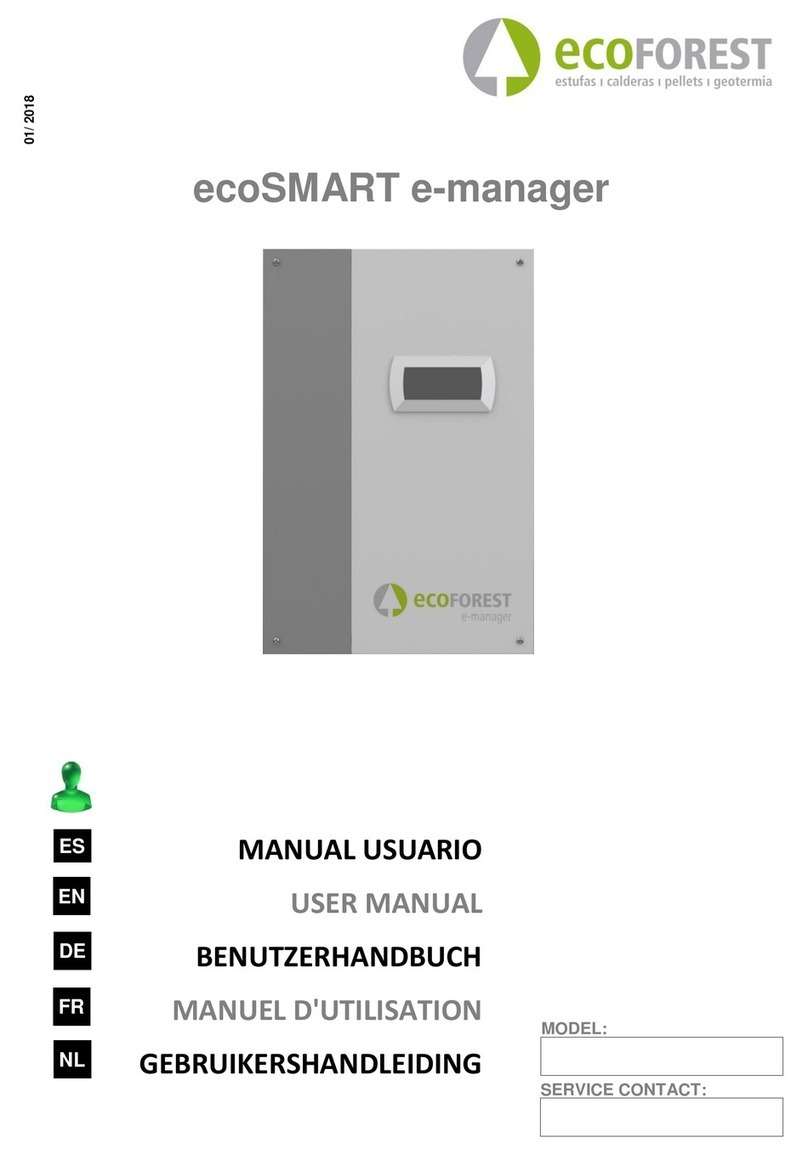
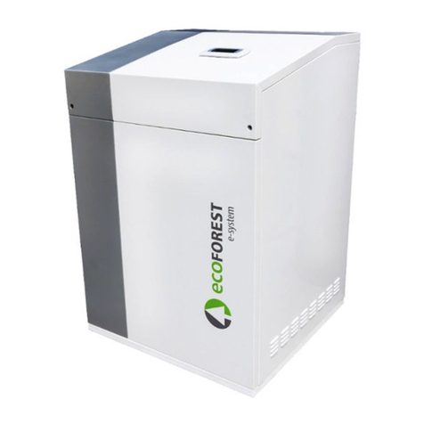
ECOFOREST ecoSMART e-source User guide

06 / 2020
SERVICE CONTACT:
MODEL:
ecoSMART e-source
USER, INSTALLER AND TECHNICAL SERVICE MANUAL
EN


ecoSMART e-source
user, installer and technical service manual
3
EN
Contents
1. General information ................................................................................................................................................................5
1.1. Safety considerations..............................................................................................................................................................5
1.2. Maintenance ...........................................................................................................................................................................6
2. General description .................................................................................................................................................................7
3. Installation ..............................................................................................................................................................................7
3.1. Transport and handling...........................................................................................................................................................7
3.2. Dimensions .............................................................................................................................................................................7
3.3. Unpacking ...............................................................................................................................................................................7
3.4. Fitting and removing the cover ...............................................................................................................................................8
3.5. Location and assembly............................................................................................................................................................8
3.6. Service areas ...........................................................................................................................................................................9
4. Electrical system ......................................................................................................................................................................9
4.1. General instructions..............................................................................................................................................................10
4.2. Power supply.........................................................................................................................................................................15
4.3. Brine collector inlet and outlet temperature probes ............................................................................................................16
4.4. Main brine pump control ......................................................................................................................................................16
4.5. Source control.......................................................................................................................................................................17
4.6. Bus communication ..............................................................................................................................................................18
5. Controller user menu guide ................................................................................................................................................... 18
5.1. Control panel ........................................................................................................................................................................19
5.2. Main screen ..........................................................................................................................................................................19
5.3. Active components ...............................................................................................................................................................19
5.4. Operating modes ..................................................................................................................................................................20
5.5. Status ....................................................................................................................................................................................20
5.6. List of user menus .................................................................................................................................................................20
5.7. Parameter adjustment ..........................................................................................................................................................21
5.8. CLOCK Menu .........................................................................................................................................................................22
5.9. INFORMATION Menu (user)..................................................................................................................................................22
5.10. ALARMS Menu ......................................................................................................................................................................23
6. Controller installer menu guide.............................................................................................................................................. 23
6.1. Language selection................................................................................................................................................................24
6.2. General management of all source.......................................................................................................................................24
6.3. Configuration of each source................................................................................................................................................25
6.4. Protection configuration.......................................................................................................................................................26
6.5. Sensor management .............................................................................................................................................................26
6.6. Information Menu (installer) ................................................................................................................................................26
6.7. Manual activation of components ........................................................................................................................................27
6.8. Default values .......................................................................................................................................................................27
6.9. Change password..................................................................................................................................................................27
7. Configuration and commissioning.......................................................................................................................................... 28
7.1. Software version and "default values"..................................................................................................................................28
7.2. pLAN address ........................................................................................................................................................................28
7.3. Enabling the e-source in the heat pump or cascade of heat pumps.....................................................................................29
7.4. pLAN communication cable connection ...............................................................................................................................30
7.5. Source manager configuration..............................................................................................................................................30

ecoSMART e-source
user, installer and technical service manual
4
EN
7.6. Final inspection and commissioning .....................................................................................................................................30
8. Identifying and solving problems ........................................................................................................................................... 31
8.1. Alarm list ...............................................................................................................................................................................31
9. Technical specifications ......................................................................................................................................................... 32
9.1. Technical data table..............................................................................................................................................................32
9.2. Circuit diagram......................................................................................................................................................................33
9.3. Table of electrical connections .............................................................................................................................................34
10. Symbols ................................................................................................................................................................................. 35
11. Warranty and technical service.............................................................................................................................................. 36
11.1. Manufacturer's warranty ......................................................................................................................................................36
11.2. Authorised distributors and technical service.......................................................................................................................36

ecoSMART e-source
user, installer and technical service manual
5
EN
1. General information
Thank you for purchasing an ecoSMART e-source source manager with your ecoGEO HP heat pump.
This manual contains information about installing, commissioning and troubleshooting the device. There is also useful information
for the end user, such how to navigate and adjust parameters via the control panel.
To ensure optimal performance of the e-source manager, read this manual carefully before installation and commissioning. Keep
this manual handy for future reference.
This manual contains two different kinds of warnings that should be heeded.
NOTE
Indicates a situation that may cause material damage or equipment malfunction. This may also be
used to indicate practices that are recommended or not recommended for the equipment.
DANGER!
Warning of imminent or potential danger which, if not avoided, may result in injury or even death.
This may also be used to warn of unsafe practices.
The e-source manager has been designed to work together with an ecoGEO HP heat pump or together with a cascade of several
ecoGEO HP heat pumps controlled by a supervisor module.
The manufacturer is not responsible for any material damage and/or personal injury resulting from improper use or incorrect
installation of the equipment.
The device must be installed by a licensed installer in accordance with applicable local regulations and in accordance with the
instructions described in the installation manual.
1.1. Safety considerations
The detailed instructions in this section cover important safety aspects and must therefore be strictly complied with.
DANGER!
All the installation and maintenance work described in this manual must be performed by an
authorised engineer.
Improper installation or use of the equipment could cause electrocution, short circuits, leakage of
working fluids, fire or other personal injuries and/or material damage.
If you are unsure of the procedures for installation, maintenance or use of the equipment, contact
your local dealer or technical support for advice.
If you detect a malfunction in the unit, contact your local dealer or technical support to answer any
questions.
This equipment should not be handled by people with physical, sensory or psychological disabilities,
children and people with no suitable experience or knowledge, unless it is under the supervision or
direction of a person responsible for their safety.
When carrying out installation, maintenance or commissioning of the heat pump, always use
appropriate personal protective equipment.
Keep the plastic bags included in the packaging out of the reach of children, as improper use could
result in injury caused by asphyxia.

ecoSMART e-source
user, installer and technical service manual
6
EN
Hydraulic installation
Installation and subsequent interventions on the hydraulic circuits controlled by the e-source manager must be performed only by
an authorised technician in accordance with applicable local regulations and the instructions provided in this manual.
DANGER!
Do not touch the pipes while the unit is in operation or immediately after, as this may result in burns
caused by cold or heat. If these components need to be touched, allow sufficient time for the
temperatures to stabilise and wear protective gloves to avoid injury.
Electrical system
Any intervention on the electrical system must only be performed by an authorised electrician in accordance with applicable local
regulations and the instructions provided in this manual.
DANGER!
The power supply to the unit must have an external switch that can shut off all the circuits. Ecoforest
recommends installing an automatic external switch for each of the electrical power sources (power
supply of the e-source manager and power supply of devices controlled by its DO digital outputs).
Please note that the unit may have more than one electrical power source.
Before performing any operation on the unit, disconnect the power supply.
During installation and maintenance of the unit, never leave the cover open unattended.
Do not touch any electrical component with wet hands, as this could cause an electric shock.
Scrapping
The e-source manager is made from a variety of materials and must therefore be delivered to an authorised centre for proper
scrapping and recycling of said materials.
1.2. Maintenance
The e-source no manager does not require any specific maintenance after commissioning. The internal controller constantly
monitors a large variety of parameters and will alert you if any problem or incident occurs, in which case we recommend that you
contact your dealer.
DANGER!
All maintenance work must be performed by an authorised technician. Improper handling of the
equipment as a whole can result in personal injury and/or damage to materials.
Do not spill water or other liquids directly on the casing or inside it, as this could cause an electric
shock or fire.

ecoSMART e-source
user, installer and technical service manual
7
EN
2. General description
The ecoSMART source manager is an electronic controller designed to manage several brine energy sources, such as geothermal
circuits or antifreeze/air aerothermal units. It can work with a single ecoGEO HP heat pump or with a cascade of several ecoGEO HP
heat pumps controlled by an ecoSMART supervisor module. In order to do so, pLAN bus communication must be established with
the heat pump or cascade of heat pumps.
The e-source manager can manage up to four independent brine sources. Each source can be configured as an aerothermal or
geothermal brine source. It is also able to control defrosting of each of the aerothermal sources independently and in sequence,
while the heat pump(s) continue(s) to work with the other sources. It can also control a general circulator pump for all brine
sources.
3. Installation
3.1. Transport and handling
Transport the e-source manager so that it is protected from bad weather.
3.2. Dimensions
The general dimensions of the unit are set out below.
Figure 3.1. General dimensions (in mm).
3.3. Unpacking
To unpack the e-source manager, carefully remove the box and check that the unit has not been damaged during transportation.
400
600
260
510
130
Ø9
158
400
600
260
510
130
Ø9
158
400
600
260
510
130
Ø9
158

ecoSMART e-source
user, installer and technical service manual
8
EN
3.4. Fitting and removing the cover
A 4 mm Allen wrench is required to assemble and disassemble the cover. Remove the front cover by loosening the four screws and
pulling it.
Figure 3.2. Removing the front cover of the e-source manager.
NOTE
When removing the cover, take care to remove the control panel cable without damaging it.
3.5. Location and assembly
Choose a dry place where there is no risk of frost. The e-source manager module must be installed on a stable wall that can support
the full weight of the unit. Use a spirit level to ensure that it is completely horizontal.
Figure 3.3. Positioning the e-source manager.

ecoSMART e-source
user, installer and technical service manual
9
EN
3.6. Service areas
The minimum recommended distances around the e-source manager to facilitate installation, commissioning and maintenance are
set out below.
Figure 3.4. Recommended minimum service areas around the e-source manager (in mm).
4. Electrical system
DANGER!
The power supply to the unit must have an external switch that can shut off all the circuits.
Ecoforest recommends installing an automatic external switch for each of the electrical power
sources (power supply of the e-source manager and power supply of devices controlled by its DO
digital outputs).
Please note that the unit may have more than one electrical power source.
Before performing any operation on the unit, disconnect the power supply.
During installation and maintenance of the unit, never leave the cover open unattended.
Do not touch any electrical component with wet hands, as this could cause an electric shock.
100
100
600
100
100

ecoSMART e-source
user, installer and technical service manual
10
EN
4.1. General instructions
The locations of the main electrical panel components are shown below.
Figure 4.1. Location of internal components.
In addition to the power supply, various temperature probes (analogue inputs AIxx), open/closed contact control signals from
thermostats or other external equipment (digital inputs DIxx), switching on/off of pumps, valves and/or fans (digital outputs DOxx)
or regulation of pumps, valves and/or fans (analogue outputs AOxx) should be connected.
Figures 4.2 and 4.3 show installation examples to indicate the electrical connections of the components.
AOxx
Analogue outputs
Communication ports
FBus, BMS and pLAN
Transformer fuse
230Vac 0.5A
Main switch
24Vac transformer
Digital outputs
DOxx
Control fuse
24Vac 2.5A
DIxx
Digital inputs
Controller pCO OEM+
Main supply 1/N/PE
230Vac
50-60 Hz
DI7 DI8
DI5
DI4
DI3
DI2
DI1
AI12
AI11AI10AI9 DI6AO5AO4AO3AO2AO1AI8
AI7
AI6
AI5
AI4AI2
AI1 AI3
Sgn
Com
Sgn
24Vac
Sgn
24Vac
Sgn
24Vac
Sgn
24Vac
Vout
24Vac
GND
PE
GND
Tx/Rx+
Tx/Rx-
Sgn
Com
Sgn
Com
Sgn
Com
Vout
24Vac
GND
Vout
24Vac
GND
Vout
24Vac
GND
Vout
24Vac
GND
Sgn
Sgn
Sgn
Sgn
Sgn
Sgn
Sgn
GND
GND
GND
GND
GND
GND
GND
Sgn
GND
Sgn
GND
Sgn
GND
Sgn
GND
Sgn
GND
PE
GND
Tx/Rx+
Tx/Rx-
PE
GND
Tx/Rx-
Tx/Rx+
pLAN BMS2 FBus
Fuse 2A
24 Vac
Control Power
Supply 230V DO1 DO2 DO3 DO4 DO5 DO6 DO7 DO8 DO9 DO10 DO11 DO12 DO13
L1 L2/N PE
Fuse 0.5A
NC
COM
NO
NC
COM
NO
NC
COM
NO
NC
COM
NO
NC
COM
NO
NC
COM
NO
NC
COM
NO
NC
COM
NO
NC
COM
NO
NC
COM
NO
NC
COM
NO
NC
COM
NO
NC
COM
NO
AIxx
Analogue inputs
Distributor 24Vac

ecoSMART e-source
user, installer and technical service manual
11
EN
T
T
DO8
DO9
DO9
AO5DO8
Defrost
heat
AI9
T
DO1
AO1
AI2
AI1
DO9
DO6
DO7
DO7
AO4DO6
Defrost
heat
AI7
T
DO7
DO4
DO5
DO5
AO3DO4
Defrost
heat
AI5
T
DO5
DO2
DO3
DO3
AO2DO2
Defrost
heat
AI3
T
DO3
Source 1 Source 3Source 2 Source 4
e-source
Figure 4.2. General electrical connection scheme 1.

ecoSMART e-source
user, installer and technical service manual
12
EN
T
T
DO1
AO1
AI2
AI1
DO6
DO7
DO7
AO4DO6
Defrost
heat
AI7
T
DO7
DO4
DO5
DO5
AO3DO4
Defrost
heat
AI5
T
DO5
DO2
DO3
DO3
AO2DO2
Defrost
heat
AI3
T
DO3
Source 1 Source 3Source 2
DO8
DO8
AI9
T
AO5
Source 4
e-source
Figure 4.3. General electrical connection scheme 2.

ecoSMART e-source
user, installer and technical service manual
13
EN
NOTE
The schemes in figures 4.2 and 4.3 are provided only to indicate the electrical connections. The
hydraulic design of the brine system should be carried out by a specialist. Its use in full or in part, as
well as any reproduction or transfer to third parties, is the responsibility of the installation company.
Analogue inputs (AIxx)
These terminals are used to connect external temperature probes. Only passive NTC temperature probes can be connected, so
cable connection polarity is not important.
If necessary, use extension cables with a maximum length of 50 m and a minimum diameter of 0.75 mm2. For greater lengths (up to
120 m) it is recommended to use cable with a section of 1.5 mm2.
NOTE
Use original temperature probes only; other types of components could cause poor heat pump
operation and/or cause heat pump component breakdowns.
Figure 4.4. Example of temperature probe connections.
Digital control inputs (DIxx)
Digital signals (open/closed contact) from thermostats or other external equipment can be connected to these terminals to control
the sources.
NOTE
Take special care with the working voltage of each digital input; improper handling could cause poor
heat pump operation and/or heat pump component breakdowns. Some digital inputs require
voltage-free signals, while others require 24Vac signals. 24Vac signals are sent from their own
terminal block strip.
Do not mix voltage-free and 24Vac signals.
Com
Sgn
AIxx
NTC
DI7 DI8
DI5
DI4
DI3
DI2
DI1
AI12
AI11AI10AI9 DI6AO5AO4AO3AO2AO1AI8
AI7
AI6
AI5
AI4AI2
AI1 AI3
Sgn
Com
Sgn
24Vac
Sgn
24Vac
Sgn
24Vac
Sgn
24Vac
Vout
24Vac
GND
PE
GND
Tx/Rx+
Tx/Rx-
Sgn
Com
Sgn
Com
Sgn
Com
Vout
24Vac
GND
Vout
24Vac
GND
Vout
24Vac
GND
Vout
24Vac
GND
Sgn
Sgn
Sgn
Sgn
Sgn
Sgn
Sgn
GND
GND
GND
GND
GND
GND
GND
Sgn
GND
Sgn
GND
Sgn
GND
Sgn
GND
Sgn
GND
PE
GND
Tx/Rx+
Tx/Rx-
PE
GND
Tx/Rx-
Tx/Rx+
pLAN BMS2 FBus
Fuse2A
24 Vac
ControlPower
Supply230V DO1 DO2 DO3 DO4 DO5 DO6 DO7 DO8 DO9 DO10 DO11 DO12 DO13
L1 L2/N PE
Fuse0.5A
NC
COM
NO
NC
COM
NO
NC
COM
NO
NC
COM
NO
NC
COM
NO
NC
COM
NO
NC
COM
NO
NC
COM
NO
NC
COM
NO
NC
COM
NO
NC
COM
NO
NC
COM
NO
NC
COM
NO

ecoSMART e-source
user, installer and technical service manual
14
EN
Figure 4.5. Example of voltage-free digital input connections.
NOTE
24Vac external equipment can be connected directly from the e-source manager, and connected
equipment as a whole must not exceed 36VA or 1.5A. Failure to comply with these ranges could
cause poor heat pump operation and/or heat pump component breakdowns.
Figure 4.6. Example of digital input connection with 24Vac voltage.
Analogue outputs (AOxx)
These terminals send analogue 0-10Vdc regulation signals to modulate the control of pumps and/or fans. Moreover, these
connectors have a 24Vac power supply terminal for modulating equipment that requires a 24Vac power supply.
Figure 4.7. Example of 0-10Vdc modulating regulation signal connections.
GND
24Vac
Vout
AOxx
M
DI7 DI8
DI5
DI4
DI3
DI2
DI1
AI12
AI11AI10AI9 DI6AO5AO4AO3AO2AO1AI8
AI7
AI6
AI5
AI4AI2
AI1 AI3
Sgn
Com
Sgn
24Vac
Sgn
24Vac
Sgn
24Vac
Sgn
24Vac
Vout
24Vac
GND
PE
GND
Tx/Rx+
Tx/Rx-
Sgn
Com
Sgn
Com
Sgn
Com
Vout
24Vac
GND
Vout
24Vac
GND
Vout
24Vac
GND
Vout
24Vac
GND
Sgn
Sgn
Sgn
Sgn
Sgn
Sgn
Sgn
GND
GND
GND
GND
GND
GND
GND
Sgn
GND
Sgn
GND
Sgn
GND
Sgn
GND
Sgn
GND
PE
GND
Tx/Rx+
Tx/Rx-
PE
GND
Tx/Rx-
Tx/Rx+
pLAN BMS2 FBus
Fuse2A
24 Vac
ControlPower
Supply230V DO1 DO2 DO3 DO4 DO5 DO6 DO7 DO8 DO9 DO10 DO11 DO12 DO13
L1 L2/N PE
Fuse0.5A
NC
COM
NO
NC
COM
NO
NC
COM
NO
NC
COM
NO
NC
COM
NO
NC
COM
NO
NC
COM
NO
NC
COM
NO
NC
COM
NO
NC
COM
NO
NC
COM
NO
NC
COM
NO
NC
COM
NO
24Vac
Sgn
DIxx
DI7 DI8
DI5
DI4
DI3
DI2
DI1
AI12
AI11AI10AI9 DI6AO5AO4AO3AO2AO1AI8
AI7
AI6
AI5
AI4AI2
AI1 AI3
Sgn
Com
Sgn
24Vac
Sgn
24Vac
Sgn
24Vac
Sgn
24Vac
Vout
24Vac
GND
PE
GND
Tx/Rx+
Tx/Rx-
Sgn
Com
Sgn
Com
Sgn
Com
Vout
24Vac
GND
Vout
24Vac
GND
Vout
24Vac
GND
Vout
24Vac
GND
Sgn
Sgn
Sgn
Sgn
Sgn
Sgn
Sgn
GND
GND
GND
GND
GND
GND
GND
Sgn
GND
Sgn
GND
Sgn
GND
Sgn
GND
Sgn
GND
PE
GND
Tx/Rx+
Tx/Rx-
PE
GND
Tx/Rx-
Tx/Rx+
pLAN BMS2 FBus
Fuse2A
24 Vac
ControlPower
Supply230V DO1 DO2 DO3 DO4 DO5 DO6 DO7 DO8 DO9 DO10 DO11 DO12 DO13
L1 L2/N PE
Fuse0.5A
NC
COM
NO
NC
COM
NO
NC
COM
NO
NC
COM
NO
NC
COM
NO
NC
COM
NO
NC
COM
NO
NC
COM
NO
NC
COM
NO
NC
COM
NO
NC
COM
NO
NC
COM
NO
NC
COM
NO
Com
Sgn
DIxx
DI7 DI8
DI5
DI4
DI3
DI2
DI1
AI12
AI11AI10AI9 DI6AO5AO4AO3AO2AO1AI8
AI7
AI6
AI5
AI4AI2
AI1 AI3
Sgn
Com
Sgn
24Vac
Sgn
24Vac
Sgn
24Vac
Sgn
24Vac
Vout
24Vac
GND
PE
GND
Tx/Rx+
Tx/Rx-
Sgn
Com
Sgn
Com
Sgn
Com
Vout
24Vac
GND
Vout
24Vac
GND
Vout
24Vac
GND
Vout
24Vac
GND
Sgn
Sgn
Sgn
Sgn
Sgn
Sgn
Sgn
GND
GND
GND
GND
GND
GND
GND
Sgn
GND
Sgn
GND
Sgn
GND
Sgn
GND
Sgn
GND
PE
GND
Tx/Rx+
Tx/Rx-
PE
GND
Tx/Rx-
Tx/Rx+
pLAN BMS2 FBus
Fuse2A
24 Vac
ControlPower
Supply230V DO1 DO2 DO3 DO4 DO5 DO6 DO7 DO8 DO9 DO10 DO11 DO12 DO13
L1 L2/N PE
Fuse0.5A
NC
COM
NO
NC
COM
NO
NC
COM
NO
NC
COM
NO
NC
COM
NO
NC
COM
NO
NC
COM
NO
NC
COM
NO
NC
COM
NO
NC
COM
NO
NC
COM
NO
NC
COM
NO
NC
COM
NO

ecoSMART e-source
user, installer and technical service manual
15
EN
Digital outputs to relay (DOxx)
The relay terminal block provides digital outputs to control external equipment, such as circulator pumps, fans or open/closed
valves. Each relay should be powered externally with the operating voltage of the component to be controlled. Power is supplied to
each relay separately, so different operating voltages can be used in each. The following figure shows an example of an installation
of a relay power supply.
Figure 4.8. Example of digital output relay power supply connections.
Each relay allows independent pole switching; it can thus control the switching on/off of the units, including those powered with a
different voltage. The capacity of the relays is 8A/250Vac per pole. If the equipment to be controlled exceeds this capacity, an
external relay or contactor must be installed. Shown below are examples of connections between circulator pumps and 3-way
valves with controls at 2 or 3 points.
NOTE
Pay special attention to the maximum consumption allowed by each relay. Use an intermediate relay
or a contactor for the connection, if necessary.
Figure 4.9. Example of digital output connections.
4.2. Power supply
The e-source manager only requires one electrical connection. The power supply to the 24Vac transformer connects to it to power
the controller and other devices with low power consumption. The following table shows the characteristics of the necessary
electrical connection:
DI7 DI8
DI5
DI4
DI3
DI2
DI1
AI12
AI11AI10AI9 DI6AO5AO4AO3AO2AO1AI8
AI7
AI6
AI5
AI4AI2
AI1 AI3
Sgn
Com
Sgn
24Vac
Sgn
24Vac
Sgn
24Vac
Sgn
24Vac
Vout
24Vac
GND
PE
GND
Tx/Rx+
Tx/Rx-
Sgn
Com
Sgn
Com
Sgn
Com
Vout
24Vac
GND
Vout
24Vac
GND
Vout
24Vac
GND
Vout
24Vac
GND
Sgn
Sgn
Sgn
Sgn
Sgn
Sgn
Sgn
GND
GND
GND
GND
GND
GND
GND
Sgn
GND
Sgn
GND
Sgn
GND
Sgn
GND
Sgn
GND
PE
GND
Tx/Rx+
Tx/Rx-
PE
GND
Tx/Rx-
Tx/Rx+
pLAN BMS2 FBus
Fuse2A
24 Vac
ControlPower
Supply230V DO1 DO2 DO3 DO4 DO5 DO6 DO7 DO8 DO9 DO10 DO11 DO12 DO13
L1 L2/N PE
Fuse0.5A
NC
COM
NO
NC
COM
NO
NC
COM
NO
NC
COM
NO
NC
COM
NO
NC
COM
NO
NC
COM
NO
NC
COM
NO
NC
COM
NO
NC
COM
NO
NC
COM
NO
NC
COM
NO
NC
COM
NO
LoffLon
L
NC: 22/12
COM: 21/11
NO: 24/14
A2/A1
DOxx
NC
COM
NO
NC: 22/12
COM: 21/11
NO: 24/14
A2/A1
DOxx
NC
COM
NO
2P 3P
DI7 DI8
DI5
DI4
DI3
DI2
DI1
AI12
AI11AI10AI9 DI6AO5AO4AO3AO2AO1AI8
AI7
AI6
AI5
AI4AI2
AI1 AI3
Sgn
Com
Sgn
24Vac
Sgn
24Vac
Sgn
24Vac
Sgn
24Vac
Vout
24Vac
GND
PE
GND
Tx/Rx+
Tx/Rx-
Sgn
Com
Sgn
Com
Sgn
Com
Vout
24Vac
GND
Vout
24Vac
GND
Vout
24Vac
GND
Vout
24Vac
GND
Sgn
Sgn
Sgn
Sgn
Sgn
Sgn
Sgn
GND
GND
GND
GND
GND
GND
GND
Sgn
GND
Sgn
GND
Sgn
GND
Sgn
GND
Sgn
GND
PE
GND
Tx/Rx+
Tx/Rx-
PE
GND
Tx/Rx-
Tx/Rx+
pLAN BMS2 FBus
Fuse2A
24 Vac
ControlPower
Supply230V DO1 DO2 DO3 DO4 DO5 DO6 DO7 DO8 DO9 DO10 DO11 DO12 DO13
L1 L2/N PE
Fuse0.5A
NC
COM
NO
NC
COM
NO
NC
COM
NO
NC
COM
NO
NC
COM
NO
NC
COM
NO
NC
COM
NO
NC
COM
NO
NC
COM
NO
NC
COM
NO
NC
COM
NO
NC
COM
NO
NC
COM
NO
L
NC: 22/12
DOxx
COM: 21/11
NO: 24/14
A2/A1
NC
COM
NO

ecoSMART e-source
user, installer and technical service manual
16
EN
Type of power supply
Type of protection/ Cut-off current
Recommended cable section
1/N/PE 230 V / 50-60 Hz
Magnetic, thermal and differential / 1A
1.5 mm2
Table 4.1. Characteristics of the e-source manager power supply.
Figure 4.10. Connection scheme of the e-source manager power supply.
NOTE
The power supply of elements controlled by DO digital outputs must be independent.
4.3. Brine collector inlet and outlet temperature probes
Install a temperature probe before the inlet of the brine collector and another after the outlet.
Description
Signal
Type
Connector
Brine collector inlet temperature
Analogue input
NTC 10K 25 °C Probe
AI1
Brine collector outlet temperature
Analogue input
NTC 10K 25 °C Probe
AI2
Table 4.2. Connection terminals for the brine collector inlet and outlet temperature probes
4.4. Main brine pump control
In installations in which hydraulic separation is necessary, it is permitted to control an additional brine circulator pump.
Description
Signal
Type
Connector
Main brine pump control
Digital output
Activation / 8A maximum
DO1
Analogue output
Regulation 0-10Vdc
AO1
Table 4.3. Connection terminals for brine circuit components.
DI7 DI8
DI5
DI4
DI3
DI2
DI1
AI12
AI11AI10AI9 DI6AO5AO4AO3AO2AO1AI8
AI7
AI6
AI5
AI4AI2
AI1 AI3
Sgn
Com
Sgn
24Vac
Sgn
24Vac
Sgn
24Vac
Sgn
24Vac
Vout
24Vac
GND
PE
GND
Tx/Rx+
Tx/Rx-
Sgn
Com
Sgn
Com
Sgn
Com
Vout
24Vac
GND
Vout
24Vac
GND
Vout
24Vac
GND
Vout
24Vac
GND
Sgn
Sgn
Sgn
Sgn
Sgn
Sgn
Sgn
GND
GND
GND
GND
GND
GND
GND
Sgn
GND
Sgn
GND
Sgn
GND
Sgn
GND
Sgn
GND
PE
GND
Tx/Rx+
Tx/Rx-
PE
GND
Tx/Rx-
Tx/Rx+
pLAN BMS2 FBus
Fuse2A
24 Vac
ControlPower
Supply230V DO1 DO2 DO3 DO4 DO5 DO6 DO7 DO8 DO9 DO10 DO11 DO12 DO13
L1 L2/N PE
Fuse0.5A
NC
COM
NO
NC
COM
NO
NC
COM
NO
NC
COM
NO
NC
COM
NO
NC
COM
NO
NC
COM
NO
NC
COM
NO
NC
COM
NO
NC
COM
NO
NC
COM
NO
NC
COM
NO
NC
COM
NO
Control Supply
230 Vac
L1
L2/N
Control Supply
230 Vac
L1
L2/N

ecoSMART e-source
user, installer and technical service manual
17
EN
4.5. Source control
It is possible to control four independent sources. The electrical connections for controlling each source are as follows.
Source 1:
Geothermal
Aerothermal
Signal
Type
Connector
Source alarm signal input
Digital input
Voltage-free (0V)
DI1
Activation of the pump or valve of the source
Digital output
Activation / 8A maximum
DO2
--
Defrost activation
Analogue output
Activation / 8A maximum
DO3
Pump regulation
Fan regulation
Analogue output
Regulation 0-10Vdc
AO2
Source inlet temperature sensor
Analogue input
NTC 10K 25 °C Probe
AI3
--
Analogue input
NTC 10K 25 °C Probe
AI4
Table 4.4. Connection terminals of source 1.
Source 2:
Geothermal
Aerothermal
Signal
Type
Connector
Source alarm signal input
Digital input
Voltage-free (0V)
DI2
Activation of the pump or valve of the source
Digital output
Activation / 8A maximum
DO4
--
Defrost activation
Analogue output
Activation / 8A maximum
DO5
Pump regulation
Fan regulation
Analogue output
Regulation 0-10Vdc
AO3
Source inlet temperature sensor
Analogue input
NTC 10K 25 °C Probe
AI5
--
Analogue input
NTC 10K 25 °C Probe
AI6
Table 4.5. Connection terminals of source 2.
Source 3:
Geothermal
Aerothermal
Signal
Type
Connector
Source alarm signal input
Digital input
Voltage-free (0V)
DI3
Activation of the pump or valve of the source
Digital output
Activation / 8A maximum
DO6
--
Defrost activation
Analogue output
Activation / 8A maximum
DO7
Pump regulation
Fan regulation
Analogue output
Regulation 0-10Vdc
AO4
Source inlet temperature sensor
Analogue input
NTC 10K 25 °C Probe
AI7
--
Analogue input
NTC 10K 25 °C Probe
AI8
Table 4.6. Connection terminals of source 3.
Source 4:
Geothermal
Aerothermal
Signal
Type
Connector
Source alarm signal input
Digital input
Voltage-free (0V)
DI4
Activation of the pump or valve
Digital output
Activation / 8A maximum
DO8
--
Defrost activation
Analogue output
Activation / 8A maximum
DO9
Pump regulation
Fan regulation
Analogue output
Regulation 0-10Vdc
AO5
Inlet temperature sensor
Analogue input
NTC 10K 25 °C Probe
AI9
--
Analogue input
NTC 10K 25 °C Probe
AI10
Table 4.7. Connection terminals of source 4.

ecoSMART e-source
user, installer and technical service manual
18
EN
4.6. Bus communication
In order for the e-source manager to function, it is essential that it has pLAN bus communication with the heat pump or with the
cascade of heat pumps for which it works. Install a three-pole, shielded AWG 20-22 cable between the following terminals.
Description
Signal
Connector
e-source
Connector
ecoGEO HP
Connector
Supervisor
e-source - ecoGEO HP communication bus
ModBus RS485
pLAN
pLAN
--
e-source - Cascade communication bus
ModBus RS485
pLAN
--
pLAN 1
1 The bus cable can be connected at any point of the pLAN network formed by the ecoGEO HP heat pumps and the Supervisor
module
Table 4.8. Connection terminals for bus communication between the e-source manager and the heat pump or cascade.
PE
GND
R/T+
R/T-
pLAN
e-source
PE
GND
R/T+
R/T-
pLAN
ecoGEO HP
Figure 4.11.Connection scheme of the pLAN bus communication cable for installations with a single heat pump.
PE
GND
R/T+
R/T-
pLAN
Supervisor
PE
GND
R/T+
R/T-
pLAN
ecoGEO HP
PE
GND
R/T+
R/T-
pLAN
ecoGEO HP
PE
GND
R/T+
R/T-
pLAN
e-source
Figure 4.12.Example pLAN bus communication cable connection for installations with a cascade of heat pumps.
Some other Ecoforest devices also communicate with each other via their pLAN ports. If you want to use the e-source manager in
an installation that has several Ecoforest controllers (e.g. a cascade of several ecoGEO HP heat pumps with an ecoSMART
Supervisor module), this will form part of the pLAN network together with the other controllers.
The pLAN port of the heat pump or of the ecoSMART Supervisor module may already have several cables connected. Connect the
bus cable from the e-source ecoSMART in the same connector together with the other cables. If it is easier, the bus cable can be
connected at any other point of the pLAN network.
5. Controller user menu guide
NOTE
The information included below corresponds to application versions launched after May 2018. Other
versions, both earlier and later, may differ slightly from the contents found in this section.
Depending on the settings configured by the technical service, there might be screens or screen
contents that are not shown.
If the following screen appears when accessing a menu, this means that the
service requested has not been enabled by the technical service.
5

ecoSMART e-source
user, installer and technical service manual
19
EN
5.1. Control panel
The e-source control panel has a screen with 6 buttons, like the one shown in the illustration below. The buttons are used to move
through the various user menus and to adjust the parameters.
Figure 5.1. Control panel.
The general functions and operation of each of the buttons are indicated below.
The ALARMS menu can be accessed directly from anywhere in the application.
The list of user menus can be accessed from anywhere in the application.
The user can return to the previous menu from anywhere in the application.
This allows the user to move through the menu lists.
This allows the user to move from one screen to another inside a menu.
This is used to adjust the settings of the parameters contained in a screen.
This allows the user to access the selected menu.
This is used to move from one adjustable parameter to another in the same screen.
This is used to access the INFORMATION menu directly from the main screen.
5.2. Main screen
The main screen of the application contains a series of fields with information about heat pump operation.
Figure 5.2. Description of the main screen.
5.3. Active components
This field shows the main components that are activated. A consumption bar is also shown for the fan and modulating circulator
pumps.
Brine source collector
Status
Main brine pump
activated
Date and time
Activated sources

ecoSMART e-source
user, installer and technical service manual
20
EN
Main brine pump activated
Geothermal source activated (source 1)
Aerothermal source activated (source 2)
Wait. The unit is initialising
STAND
-BY
The unit is on and awaiting the activated command
5.4. Operating modes
This field shows icons that indicate the current operating mode of the e-source.
Brine sources in operation. It also indicates the brine source collector inlet and outlet temperatures.
Wait. The unit is initialising.
STAND-BY
The unit is on and awaiting the activated command.
5.5. Status
This indicates e-source availability to service the various heat pump functions.
ON status
The e-source is on as commanded by the heat pump or cascade of heat pumps.
OFF status
The e-source is off as commanded by the heat pump or cascade of heat pumps.
5.6. List of user menus
Follow the instructions below to browse through the various user menu screens. Each menu has a series of screens that are used to
adjust parameters and view desired information.
Table of contents
Other ECOFOREST Control System manuals
Popular Control System manuals by other brands

Bosch
Bosch Rexroth NYCe 4000 Hardware manual

ccei
ccei Tild Technical manual
Lennox
Lennox Harmony III installation instructions

NUM
NUM 1020 SUPPLEMENTARY PROGRAMMING MANUAL

Doosan
Doosan B20S-3 Specifications Systems Operation Testing & Adjusting

Wuhan Huazhong Numerical Control Co., Ltd
Wuhan Huazhong Numerical Control Co., Ltd HNC-18iT v4.0 Programming guide
