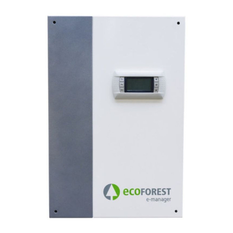
ECOFOREST ecoSMART e-system User manual

10 / 2020 VERSIÓN SOFTWARE v07b05
ecoSMART e-system
MODEL:
SERVICE CONTACT:
USER MANUAL
EN


User manual ecoSMART e-system
1
EN
Contents
1. General information ............................................................................................................................................... 2
1.1. Safety considerations .............................................................................................................................................. 2
1.2. Steps to follow in case of fire .................................................................................................................................. 3
1.3. Maintenance ........................................................................................................................................................... 3
2. System diagram ...................................................................................................................................................... 4
3. Controller guide...................................................................................................................................................... 6
3.1. Control panel........................................................................................................................................................... 6
3.2. Main screen............................................................................................................................................................. 7
3.3. Controller status...................................................................................................................................................... 7
3.4. Operating modes..................................................................................................................................................... 7
3.5. Señales de salida activas en el controlador............................................................................................................. 7
3.6. List of installer menu ............................................................................................................................................... 9
3.7. Parameters adjustment......................................................................................................................................... 10
3.1. ON/OFF Menu ....................................................................................................................................................... 10
3.2. SCHEDULE Menu ................................................................................................................................................... 10
3.3. SURPLUS CONFIGURATION Menu......................................................................................................................... 11
3.4. CONSUMPTION CONTROL Menu .......................................................................................................................... 11
3.5. NON-CRITICAL LOADS Menu ................................................................................................................................. 11
3.1. INFORMATION Menu ............................................................................................................................................ 11
3.2. ALARMS Menu....................................................................................................................................................... 12
4. Simbols..................................................................................................................................................................14
5. Alarms and troubleshooting ..................................................................................................................................14
5.1. Active alarms ......................................................................................................................................................... 14
6. Technical specifications .........................................................................................................................................15
7. Warranty and technical service..............................................................................................................................17
7.1. Manufacturer's warranty ...................................................................................................................................... 17
7.2. Authorised distributors and technical service....................................................................................................... 17

User manual ecoSMART e-system
2
EN
1. General information
Thank you for purchasing our ecoSMART e-system device.
This manual contains information about general performance of the system and how to use the controller functions. The user can
also find information on how to deal with anomalous performance and some of the most common malfunctions that can be solved
without external assistance.
For best performance of the ecoSMART equipment and your ECOFOREST heat pump, read this manual carefully before using. Keep
this manual for future reference.
This manual contains two different kinds of warnings that should be heeded, as shown below.
NOTE
▪Indicates a situation that may cause material damage or malfunctioning of the equipment. May also be
used to indicate practices which are recommended or not recommended for the equipment.
DANGER!
▪Warning of imminent or potential danger which, if not avoided, may result in injury or even death. May
also be used to warn of unsafe practices.
The ecoSMART e-system has been designed to work with ecoGEO heat pumps and a serie of commercial trades and installations
designed for the production of energy from renewable sources or similar equipment.
The manufacturer is not responsible for any material damage and/or personal injury resulting from improper use or incorrect
installation of the equipment. ECOFOREST equipment must be installed by a licensed installer in accordance with applicable local
regulations and in accordance with the instructions described in the installation manual.
1.1. Safety considerations
The detailed instructions in this section cover important aspects for your safety; as such they must be strictly complied with
DANGER!
▪All the installation and maintenance work must be performed by an authorised technician following
local regulations and according to the instructions described in the installation manual.
▪Improper installation or use of the equipment could cause electrocution, short circuits, leakage of
working fluids, fire or other personal injury and/or material damage.
▪Keep the plastic bags included in the packaging out of the reach of children, as they could result in
injury through asphyxia.
▪This equipment should not be handled by people with physical, sensory or psychological disabilities,
children and people with no suitable experience or knowledge, unless it is under the supervision or
direction of a person responsible for their safety.
▪If equipment malfunction is detected, contact your technical service to solve any problems that may
have appeared.
▪Do not touch any of the internal components during or immediately after operation. You must
completely disconnect the equipment and isolate it from all electrical circuits before any handling or
maintenance work.
▪Install a RCD (Residual Current Device) on each AC line leaving the system.
▪The RCD must be of the quadripolar type, with a maximum residual current equal to 300mA, class A.
▪Take every precaution to prevent the storage system from turn-on uncontrollably.
▪If it is unavoidable to carry out any operation under voltage, it is totally forbidden to do so without
the appropriate PPE: anti-electrocution gloves and safety shoes.
▪Do not install or handle the e-system near flammable materials or in potentially flammable
atmospheres

User manual ecoSMART e-system
3
EN
1.2. Steps to follow in case of fire
Electrical devices may ultimately cause a fire due to faulty installation or improper use of the equipment. The measures taken must
ensure the safety of persons in the first place, as well as prevent further material damage. In case of fire inside or near the e-system,
follow the instructions below:
-Disconnect the e-system and isolate it from the mains by turning off the magneto-thermal switch on the general switchboard,
downstream from your energy meter.
-The fire must be extinguished by means of convectional agents, as this is a system considered to be of low voltage, with output
voltages of less than 600Vac.
-In the event of a fire in the batteries, only dry powder extinguishers may be used. Liquid fire extinguishers are prohibited.
DANGER!
▪Remember that, with the exception of small, localised fires, only the fire brigade is equipped and
authorised to intervene in fire-extinguishing manoeuvres. If the fire has spread, you must leave the site
and get to safety immediately.
1.3. Maintenance
The ecoSMART equipments do not require specific maintenance after commissioning. The internal controller monitors a large number
of parameters and will produce a warning if any problem arises, in which case we recommend you contact your distributor.
DANGER!
▪All maintenance work must be performed by an authorised technician. Improper handling of the
equipment as a whole can result in personal injury and/or damage to materials.
▪Do not spill water or other liquids directly on the device to clean it, as this could cause an electric shock
or fire.
▪Do not manipulate or bypass the electrical protections of the devices. It could cause irreversible damage
to the equipment.
▪Do not make any changes to the electrical connection and communication lines to the storage system
without the express permission of the manufacturer.

User manual ecoSMART e-system
4
EN
2. System diagram
The smart energy management system ecoSMART regulates the energy flow between the heat pump and your self-consumption
installation in an efficient way. The control is able to adjusting the consumption of the heat pump to the electrical generation at any
given time, ensuring that the comfort of the home, configured in the heat pump, is not compromised. In this way we are able to
considerably reduce dependence on the electricity grid to supply the pump, which means a huge improvement in the total efficiency
of the installation and significant savings in the electricity bill.
Figure 2.1. General diagramo f the e-system
The proprietary software incorporated in the ecoSMART e-system allows to choose from a range of functions to maximise the
performance of your installation.

User manual ecoSMART e-system
5
EN
Control of electrical surplus.
The ecoSMART e-system is able to determine when we are facing an energy surplus situation. In this case, and under a series of
configurable conditions for the beginning and end of the regulation, the control will adjust the consumption of the heat pump to take
advantage of this surplus in the production and storage of thermal energy, so that it is obtained with less consumption when the
electricity production from renewable sources falls.
Consumption control through heat pump regulation.
When the electrical consumption of your installation approaches a maximum value that can be configured by the installer, the heat
pump can limit its power to try to keep total consumption below the limit.
Control of non-critical loads.
It is possible to program the activation and deactivation of up to four non-critical loads by enabling four output relays supplied at
230V, configuring a series of parameters associated with the energy balance between the electrical grid and the consumption of the
installation.
Battery electrical storage
The ecoSMART e-system manages the charge and discharge of a bank of lithium-ion batteries of up to 12kWh capacity, which allows
to accumulate part of the surplus to supply the electrical consumption of your home when there is no production or to charge the
batteries from the grid when the energy is cheaper. As it is a modular system, you can adapt the capacity of the bank to your particular
needs.
“Plug&play” system.
The ecoSMART e-system integrates all the necessary elements for the start-up and correct operation of a photovoltaic self-
consumption system (with the exception of the PV modules) inside the case, which reduces costs, minimises the space required and
facilitates its installation.
Smart, versatile and intuitive management.
The system continuously monitor the operation of the installation and alerts us if there are any problems. The application interface
allows to easily visualise and control the functions of the e-system.

User manual ecoSMART e-system
6
EN
3. Controller guide
NOTE
•Depending on the software version and configuration established by the technical service, there may be
screens or contents that are not shown.
•If the following screen appears when accessing menu, this means that the service requested has not
been enabled by the technical service.
3.1. Control panel
The energy manager control panel has a screen with 6 buttons, like the one shown in the illustration below. The buttons are used to
move through the various user menus and to adjust the parameters.
Figure 3.1. Control panel
The general functions of each of the buttons and operation is indicated below.
The ALARMS menu can be accessed directly from anywhere in the application.
The list of user menus can be accessed from anywhere in the application.
The user can return to the previous menu from anywhere in the application.
This allows the user to move through the menu lists.
This allows the user to move from one screen to another inside a menu.
This is used to adjust the settings of the parameters contained in a screen.
This allows the user to access the selected menu.
This is used to move from one adjustable parameter to another in the same screen.
This is used to access the INFORMATION menu directly from the main screen.
5h

User manual ecoSMART e-system
7
EN
3.2. Main screen
The main screen of the application contains a series of fields with information about e-system operation.
Figure 3.2. Description of the main screen
3.3. Controller status
The status indicates the availability of the control to attend the different functions of the e-system.
ON status
The controller is on and available to activate all its functions.
OFF status from control panel
The heat pump is switched off from the front panel of the controller and is therefore not available to activate any of its
functions.
Estado de EMERGENCIA por alarma activa
The controller is in a state of emergency because of an active alarm. The controller still run but the alarm warns us of
abnormal behavior and registers it.
3.4. Operating modes
The operating modes active in the ecoSMART e-system are reflected in the main screen and give a quick reading of the behavior of
the control at any time.
SURPLUS CONTROL Mode
When the comfort conditions are met, the control system regulates the heat pump consumption in order to use the only
the excess electricity
CONSUMPTION CONTROL Mode
The control unit regulates the consumption of the heat pump in order to adjust the total consumption of the system to
the maximum limit set by the installer.
3.5. Señales de salida activas en el controlador
The main display also shows the signals at the active outputs sent by the controller at the bottom of the screen.
//9 Vie 4:5
kW
38
kW
%
Energy meters
Active relays
Fecha y hora
Regulation output
Status
Active regulation
mode

User manual ecoSMART e-system
8
EN
REGULATION signal
An output for speed control of the heat pump compressor has been activated.
NON CRITICAL LOAD ACTIVE signal
Relay output to non-critical load enabled (up to four loads).

User manual ecoSMART e-system
9
EN
3.6. List of installer menu
Follow the instructions below to browse through the various user menus. Each menu has a series of screens that are used to change
heat pump STATUS and OPERATION MODE, adjust comfort parameters and view desired information.
Figure 3.3. Browsing through the list of user menus.
XXXXXX
XXXXXX
XXXXXX
//9 Fri 4:5
kW
38
kW
%
4:5 User menu /7
On/Off
Date and hour
Surplus control
4:5 User menu /7
On/Off
Date and hour
Surplus control
4:5 User menu 3/7
Date and hour
Surplus control
onsumption control
User menu 4/7
Surplus control
onsumption control
Non-critical loads
User menu 5/7
onsumption control
Non-critical loads
Information
User menu /7
Non-critical loads
Information
Alarms
User menu 7/7
Non-critical loads
Information
Alarms

User manual ecoSMART e-system
10
EN
3.7. Parameters adjustment
Take the following steps to change a parameter:
1. Search for the screen containing the parameter that needs adjusting (figure 5.4).
2. With the cursor in position 1 press on to enter the screen and move the cursor to the parameter in position 2.
3. Adjust the parameter in position 2 using buttons .
4. Press to accept and move the cursor to position 3.
5. Adjust the parameter in position 3 with buttons .
6. Press to accept and return to position 1.
7. With the cursor in position 1 again, press buttons to go to the previous or next screen, or to return to the list of
user menus.
Figure 3.4. Adjusting comfort parameters
3.8. ON/OFF Menu
On/Off
Shows the unit address.
Used to switch the energy manager on / off or to activate the EMERGENCY status.
3.9. SCHEDULE Menu
Date/Time
This is used to adjust the day of the week, date (DD/MM/YY) and time (HH:MM 24-hour
format) of the controller.
4:5 User menu /7
On/Off
Date and hour
Surplus control
/8
On/Off
Unit address:
State:
4:5 User menu /7
On/Off
Date and hour
Surplus control
/8 Date/Hour
Day:
Monday
Date:
//5
Hour:
7:5
DHW set
Enable:
SetT:
Position 2
Position 3
Position 1

User manual ecoSMART e-system
11
EN
Daily saving time
The settings of automatic daylight time change between seasons (autumn-winter / spring-
summer) can be adjusted.
3.10. SURPLUS CONFIGURATION Menu
Surplus control
Enables de control of electrical surplus.
3.11. CONSUMPTION CONTROL Menu
Consumption control
Enables de consumption control throught the heat pump power regulation.
3.12. NON-CRITICAL LOADS Menu
Enable loads
It allows enabling up to four independent non-critical loads through the output relays of
the manager.
3.13. INFORMATION Menu
Press for quick access to the information menú from the main screen
Daily saving time
Enable:
Transition time:
min
Start: LAST SUNDAY
in MARH at :
End: LAST SUNDAY
in OTOBER at 3:
4:5 User menu 3/7
Date and hour
Surplus control
onsumption control
3/8
Surplus control
Enable:
User menu 4/7
Surplus control
onsumption control
Non-critical loads
4/8 onsumption control
Enable:
User menu 5/7
onsumption control
Non-critical loads
Information
/8 Enable loads
Enable load :
Enable load :
Enable load 3:
Enable load 4:
User menu
/7
Non-critical loads
Information
Alarms

User manual ecoSMART e-system
12
EN
Grid balance
Displays information regarding the actual instantaneous balance read at the border, the
set for surplus regulation and the configured consumption limit.
Power meters
Allows to visualize in real time the power flow exchanged in each point of the installation.
Maximeters
Allows to visualize for every month the values of the maximum power in the different
points of the installation: maximum total power consumed by the installation, maximum
power generated in the source and maximum power consumed from the electrical
network.
Grid meters
Allows to visualize for every month the values of consumed and injected energy to the grid.
Installation meters
Allows to visualize for each month the values of electrical energy generated by the panels
with their useful use coefficient (energy generated used in the installation, that is to say,
that it is not dumped to the grid) and the total energy consumed by the installation with
its solar coverage ratio (self-consumed generated energy) for the same.
Heat pump meters
Allows to visualize the electrical energy consumed and thermal energy produced by the
heat pump for each month. It also shows the ratio of energy consumed by the pump that
has been covered by solar generation and the ratio of thermal energy produced in surplus
regulation.
Version
Includes information about e-system software version and the controller software.
3.14. ALARMS Menu
Press for quick access to the alarms menú from the main screen.
/7 Grid balance
Real: 7kW
Surplus: kW
onsum limit: -44kW
Power meters
onsumption: 38W
Generation:
457W
Grid: 95W
Batteries:
W
-44kW Batt level: %
Maximeters
SEPTEMBER
38W
onsumption: 5kW
95W
Generation:
49kW
%
Grid: kW
Grid meters
SEPTEMBER
onsumption: 83kWh
Injection:
3kWh
kW
Installation meters
SEPTEMBER
Generation:
87kWh
Useful: 99%
3kWh
onsumption: 873kWh
Solar: 7%
Heat pump meters
SEPTEMBER
onsumption: 37kWh
Production:
985kWh
873kWh Solar: 7%
Surplus: 38%
Version
Ver:
B5_EM_V3B_E
Date:
//9
Bios:
4
5//4
Boot:
45
4//3

User manual ecoSMART e-system
13
EN
Alarms
This screen displays the active alarms. The button illuminates.
Reset alarms
It allows us to reset alarms once solved.
User menu 7/7
Non-critical loads
Information
Alarms
8/8
Alarms
Lost comm
with the Modbus slave
Reset alarms
Reset alarms:

User manual ecoSMART e-system
14
EN
4. Simbols
e-system On/Off Status.
Alarm.
e-system surplus control mode active.
e-system consumption control mode active.
Active heat pump compressor regulation.
Active non-critical load.
Generated power.
Consumption/Injection from/to the public
grid.
5. Alarms and troubleshooting
5.1. Active alarms
An alarm icon on the main display screen indicates a malfunction of the e-system. In this case, the red alarm LED on the display
remains on. It can also happen that the display does not show any alarm signal, but the LED flashes, which means that there has
been an alarm that has already been solved. In both cases, you can access the alarm log to check the status of the machine.
Alarm message
Diagnosis
Steps
Loss of com. with the heat
pump.
Communication with the heat
pump has been lost.
-Check that the inverter is on and powered.
-Check the connection of the heat pump with the controller in the panel. Make
sure the wires are not damaged.
-Check the pLAN port settings in the installer menu.
Loss of communication with
the inverter.
Communication with the inverter
has been lost.
-Check that the inverter is on and powered.
-Check the connection of the inverter with the controller in the panel. Make
sure the wires are not damaged.
Inverter failure.
There has been a problem with the
solar inverter.
-Access the alarm log to view the failure code.
Table 5.1. List of alarms on the control panel
In the event that your e-system registers a communication alarm, and once you have made sure that the wires connection is correct,
on many occasions the solution could be to reset the default values of the equipment. If the problem persists, please contact the
ECOFOREST technical service.

User manual ecoSMART e-system
15
EN
6. Technical specifications
DC Input
Max. DC recommended power
5.000
W
Number of MPPT´s
2
Strings per MPPT
1/1
MPPT voltage range
125-530
V
DC max. voltage
550
V
DC rated voltage
360
V
Max. current per MPPT
12
A
Max. short circuit current per MPPT
15
A
DC Internal charger regulator
Battery type
Lithium-ion
Battery capacity range
2.400-12.000
Wh
Max. number of modules in parallel
5
Rated battery range
48
V
Battery voltage range
40-60
V
Charge max. current
50
A
Recharge curve
3-stage adapter with maintenance
Over-current/temperature protection
Yes
Interfaz de comunicación
Can/RS232
Electronic AC power supply
Max. voltage
63
W
Rated voltage
230
V
Max. current
0,5
A
AC Output
Waveform
Sinusoidal monofásica
AC rated power
4.600
W
AC rated voltage
230
V
AC rated voltage range
180-270
V
Frequency
50-60
Hz
AC rated current
20
A
Max. AC current
21,7
A
Total harmonic distorison (THD)
<3
%
Power factor
1
__
EPS CA Output
EPS power
2.000
VA
EPS voltage
230
V
Frequency
50-60
Hz
EPS current
11
A
Total harmonic distorison (THD)
<3
%
Connection time
<5
s

User manual ecoSMART e-system
16
EN
Battery module
Type
LiFePO4
Rated voltage
48
V
Rated capacity
2.400
Wh
Usable capacity
2.200
Wh
DOD
90
%
Charge voltage
52,5-54
V
Discharge voltage
45-54
V
Recommended charge/discharge current
25
A
Max. charge/discharge current
50
A
Charge/discharge peak current (15 s)
100
A
Work temperature
Charge
0-50
℃
Discharge
-10-50
℃
Dimensions WxHxD
440x88,5x410
mm
Weight
24
Kg
Desing life (25℃)
>10
year
Life cycle (25℃, 90% DOD)
>4.500
cycles
Communication interfaces
RS232, RS485, CAN
Certifications
TüV/CE/UN38.3
Efficiency
Max. Invertir efficiency
97,6
%
Euro efficiency
97
%
MPPT efficiency
99,9
%
Safety and protections
Overload protection
Yes
Overtemperature protection
Yes
Overvoltage/undervoltage protection
Yes
Overload protection category
III (grid side) II (PV side)
DC isolation impedance
Yes
DC injection monitoring
Yes
Anti-islanding protection
Yes
PV overcurrent protection
Fuses 12A DC (positive and negative pole)
Battery overcurrent protection
DC Fuse 50A
AC line protection
External installation
EPS line protection
External installation
Others
Inverter topology
Transforless
Protection class
IP20 (indoor use)
Operating temperature range
-20-60
℃
Sound emission
<40
dB
Standby consumption
<42
W
Dimensions WxHxD
720x1058x710
mm
Weight (only with one module)
118
Kg
EMC Standard
IEC61000-6-1/2/3/4

User manual ecoSMART e-system
17
EN
7. Warranty and technical service
7.1. Manufacturer's warranty
ECOFOREST is liable for lack of conformity of the product or its spare parts, in compliance with the current regulations of the country
where the product is purchased. The warranty is only valid in the country where the product is purchased.
In addition, with previous consent from ECOFOREST, the local authorised distributor can offer an extension of the warranty
established by current legislation.
Conditions and validity of the warranty
In order for this warranty to be considered valid the following conditions must be verified.
ECOFOREST must allow the product under warranty to be sold in the country where it is going to be installed.
The product under warranty must be used exclusively for the purpose that it was designed for.
All installation, start-up and repair work carried out on the equipment must be performed by a technical service authorised by
ECOFOREST.
All replacement of parts must be carried out by a technical service authorised by ECOFOREST and always with original
ECOFOREST spare parts.
The purchaser must inform in writing the establishment that sold the product of the lack of conformity, as well as the serial
number of the product and the date of purchase, within 30 (thirty) days since you became aware of said nonconformity.
For the warranty to be effective, the purchaser must present a legal document that supports the date of purchase duly stamped
and signed from the establishment that made the sale.
Disclaimer of warranty
The warranty does not include product non-conformities derived from:
Weather conditions, chemical agents, improper use and other causes that do not depend directly on the product.
Installation and/or handling of the equipment by unauthorised personnel.
Installation, maintenance or repair not adjusted to the procedures described in the documentation for this purpose by
ECOFOREST.
Improper transportation of the product.
Parts wear due to normal equipment operation, unless due to a manufacturing defect.
Request for service under warranty
A request for service during the warranty period must be presented at the establishment where the product was purchased,
indicating in writing the reason for the non-compliance, serial number and date of purchase of the product.
Product returns will only be accepted if previously accepted in writing by ECOFOREST.
The product must be returned in its original packaging and with a legal document that supports the date of purchase from the
establishment that made the sale.
7.2. Authorised distributors and technical service
ECOFOREST has an extensive network of authorised companies that distribute and perform the technical service on its products. This
network will provide our customers with all the information and technical support they need, anywhere and under any circumstance.

NOTES :
...............................................................................................................................................................
...............................................................................................................................................................
...............................................................................................................................................................
...............................................................................................................................................................
...............................................................................................................................................................
...............................................................................................................................................................
...............................................................................................................................................................
...............................................................................................................................................................
...............................................................................................................................................................
...............................................................................................................................................................
...............................................................................................................................................................
...............................................................................................................................................................
...............................................................................................................................................................
...............................................................................................................................................................
...............................................................................................................................................................
...............................................................................................................................................................
...............................................................................................................................................................
...............................................................................................................................................................
...............................................................................................................................................................
...............................................................................................................................................................
...............................................................................................................................................................
...............................................................................................................................................................
...............................................................................................................................................................
...............................................................................................................................................................
...............................................................................................................................................................
...............................................................................................................................................................
...............................................................................................................................................................
...............................................................................................................................................................
...............................................................................................................................................................
...............................................................................................................................................................
...............................................................................................................................................................
...............................................................................................................................................................
...............................................................................................................................................................
...............................................................................................................................................................
...............................................................................................................................................................
...............................................................................................................................................................
...............................................................................................................................................................
...............................................................................................................................................................
Table of contents
Other ECOFOREST Control System manuals
Popular Control System manuals by other brands
Amazone
Amazone Amatron+ operating manual
Toshiba
Toshiba TOSDIC-CIE DS Hardware operation manual

Sutter Instrument
Sutter Instrument Lambda 10-2 Operation manuals
Powrmatic
Powrmatic MC200/V3 Installation & servicing manual
SNAP PAC BRAINS
SNAP PAC BRAINS SNAP-PAC-EB1 user guide

Waterway
Waterway NEO 1100 instruction manual

