Ecoplus EP-600-ULT Service manual
OWNER’S MANUAL & INSTALLATION GUIDE
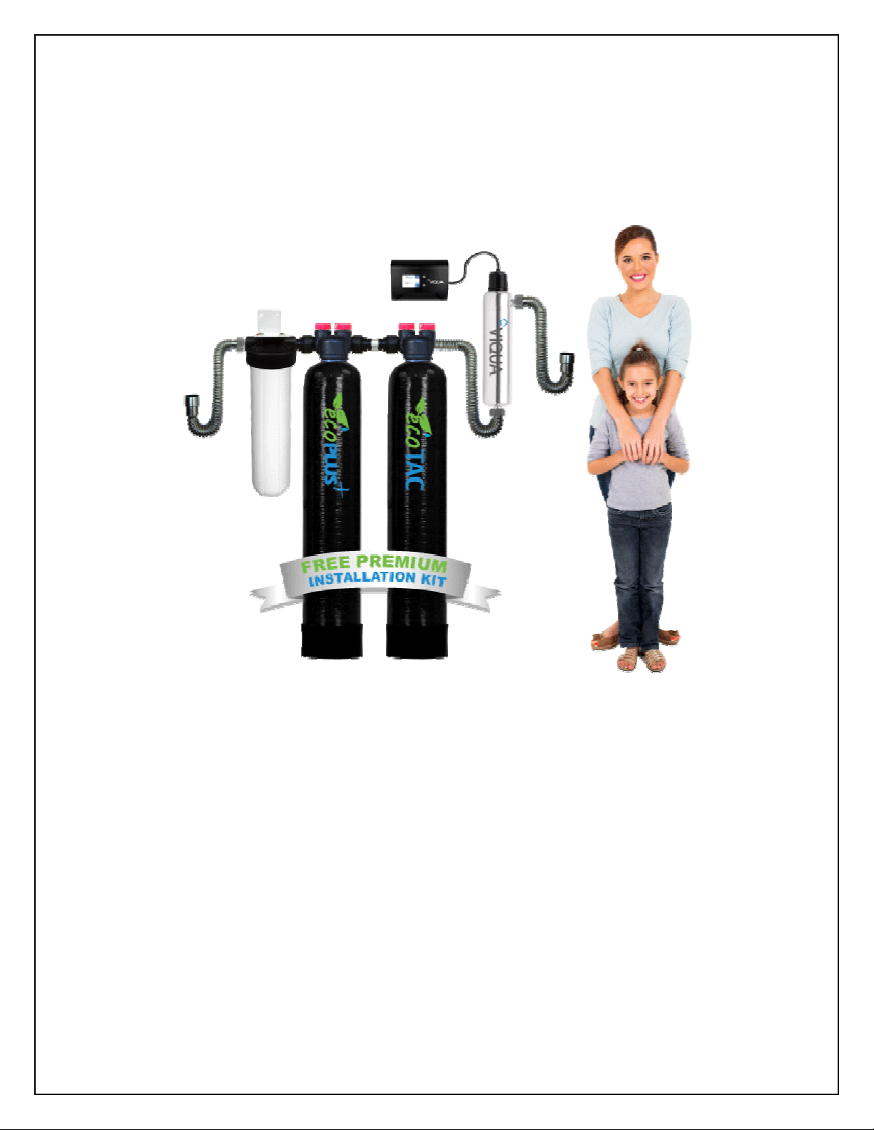
ecoPLUS™ EP-600-ULT
PLEASE READ THIS MANUAL CAREFULLY BEFORE
ATTEMPTING INSTALLATION. FAILURE TO FOLLOW THESE
INSTRUCTIONS MAY AFFECT THE PERFORMANCE OF YOUR
SYSTEM VOID YOUR WARRANTY AND RESULT IN
PROPERTY DAMAGE.

2
Congratulations on the purchase of your ecoPLUS™ Series premium whole house water
filtration system.
Our ecoPLUS™ EP-600-ULT premium whole house water treatment system combines the
powerful chlorine removal capacity of our ecoPLUS™ system our ecoTAC™ salt-free hard
water conditioning system and a powerful UV disinfection system to provide wide-spectrum
treatment for your home.
ecoPLUS™ is specifically engineered to treat city water by removing chlorine chloramine
disinfection by-products bad tastes and odors and other trace contaminants including
VOCs pesticides herbicides organic chemicals lead and more. ecoPLUS™ delivers
refreshing great tasting drinking water and protects your skin and hair from the damaging
effects of these contaminants.
Our ecoTAC™ hard water conditioners use a salt-free water treatment technology called
Template Assisted Crystalization (or "TAC" for short) to prevent hard water scale problems in
your plumbing system appliances and more.
Our ecoPLUS™ EP-600-ULT system also includes a premium grade ultraviolet (UV) sterilizer
which disinfects the water without the use of any chemicals ensuring your water is free of
harmful bacteria viruses and other microbiological contaminants like cryptosporidium and
giardia (beaver fever).
To get maximum performance from your ecoPLUS™ system we encourage to read this
manual in its entirely before installation and operation of your filter.
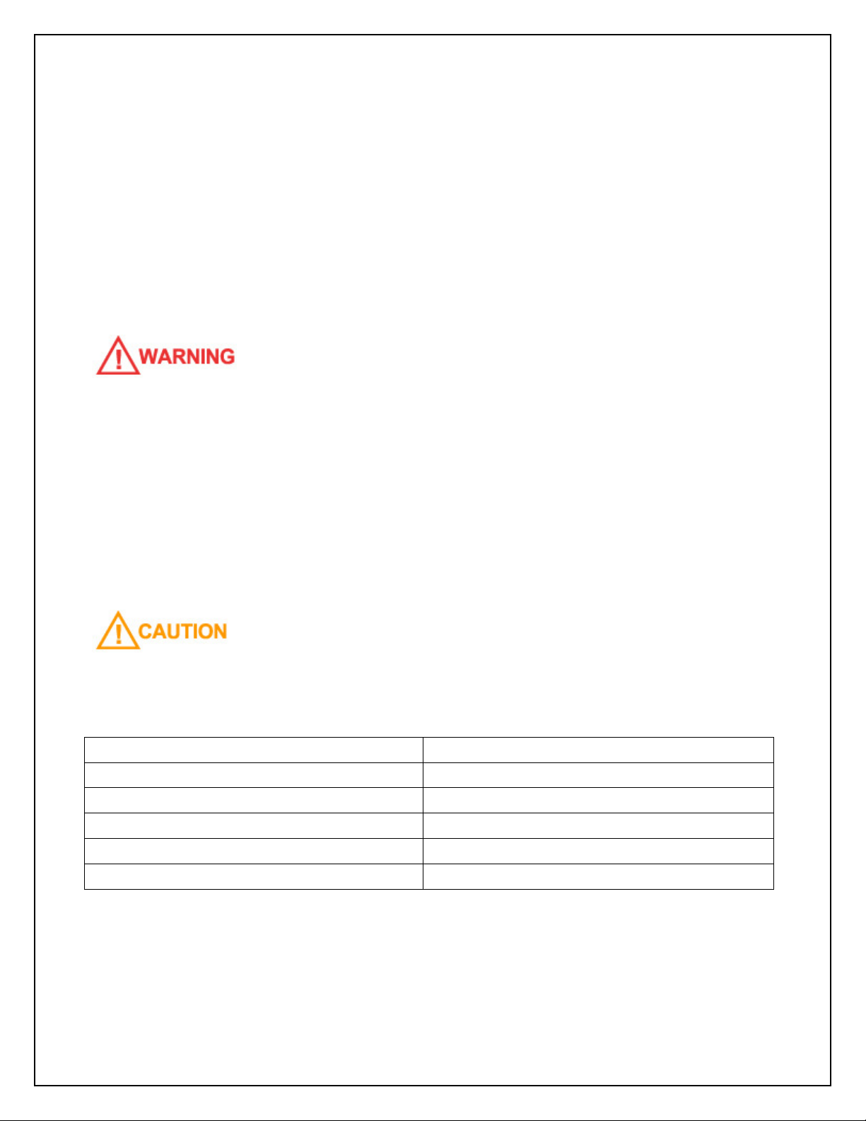
IMPORTANT SAFETY SYMBOLS
Hazards or unsafe practices that may result in personal injury
and/or severe property damage.
Hazards or unsafe practices that may cause operational
problems with your water treatment system.

3
Table of Contents:
GENERAL WARNINGS ……………………………………………………………………………………………...….. …….. 4
OPERATING CONDITIONS …………………………………………………………………………………………….…... 5
INSTALLATION ………………………………………………………………………………………………………….…..…..….. 6
Step 1 – Pre-Installation Inspection ……………………………………………………………..……… 8
Step 2 – Selecting an Installation Location ………………………………………………..…..... 10
Step 3 – Attach Mounting Bracket to Housing Cap ………………………………..……… 11
Step 4 – Attach Housing Cap to Wall …………………………………………………………………. 11
Step 5 – Install Cartridge Filter and Attach Sump ……………………………………….…… 13
Step 6 – Connect Outlet Assembly to the Bypass Assembly ……………………..…. 13
Step 7 – Connect the Bypass Assembly to ecoTAC™ Valve Head …………..….. 14
Step 8 – Connect the Inlet Assembly to the Housing Cap ………………………..…… 15
Step 9 – Connect the Bypass to the Inlet Assembly …………………………………..…….. 16
Step 10 – Connect the ecoPLUS™ Tank to the Inlet Assembly …………………….… 16
Step 11 – Connect Bridge Assembly to the ecoPLUS™ Bypass …….……………… 18
Step 12 – Connect ecoTAC™ System ……………………………………………………………......…. 18
Step 13 – Mount & Install UV Sterilizer …………………………………………………………………. 19
Step 14 – Turn off the Water & Electric Water Heaters ………………………………….… 20
Step 15 – Connect the System to Inlet and Outlet Pipes ………………………………… 20
Step 16 – Initial Start-up and Leak Testing …………………………………………………......…. 22
Step 17 - System Disinfection ………………………………………………………………………………… 23
WHAT TO EXPECT IN THE FIRST FEW WEEKS ………………………………..………………….…..…… 24
TROUBLESHOOTING ………………………………………………………………………….……………………….…..…… 25
MAINTENANCE ………………………………………………………………………………….…………………….…..….……. 26
VALIDATIONS ……………………………………………………………………………………..…………………….…..….……. 28
SATISFACTION GUARANTEE ……………………………………………………….…………………….…..….……. 30
WARRANTY INFORMATION …………………………………………………………………………………..……..…… 30

4
GENERAL WARNINGS
Do not allow children or pets to play on or around the water filter.
Do not install or store this filter system where it will be exposed to freezing temperatures.
Do not tamper with controls.
Do not repair replace or attempt to service any part of the system unless specifically
instructed to in this manual and you have the understanding tools and skills necessary to
carry out the procedure.
Packing materials can be dangerous to children. Keep all packing material (plastic bags
polystyrene boxes etc.) well out of children’s reach.
Individual components of this water treatment system and the installed system are heavy.
Precautions should be taken to prevent personal injury or strain. Do not move heavy
components without assistance if you are not physically capable of safely carrying out the
procedure.
If the water treatment system is to be left unattended for an extended period of time
(vacation etc.) we strongly recommend that you turn off the water supply to the system or
the whole house while you are away.
If your water pipes are metal (galvanized or copper) they may be used to ground electrical
systems appliances or your phone line. If this is the case be sure to install regulation
ground clamps to the metal pipe on each side of the filter system and connect a jumper wire
between the 2 clamps (#4 gauge solid copper wire is recommended). Consult a certified
electrician or plumber if you are unsure.
This water treatment system is designed specifically for the treatment of chlorinated city
water supplies. ecoPLUS™ is not intended to be used to treat water from private wells or
private surface water sources.
5
OPERATING CONDITIONS
The following chart provides guidance on the conditions required for successful operation of
your ecoPLUS™ system.
This water treatment system is designed specifically for the treatment of chlorinated city
water supplies. ecoPLUS™ is not intended to be used to treat water from private wells or
private surface water sources. If you are unsure of the status of your water supply please
contact your dealer for assistance.
USE OF THIS EQUIPMENT OUTSIDE OF THESE OPERATING CONDITIONS MAY
ADVERSELY AFFECT THE PERFORMANCE OF YOUR SYSTEM RESULT IN SYSTEM
DAMAGE INCLUDING WATER LEAKS AND CORRESPONDING PROPERTY DAMAGE AND
MAY VOID YOUR WARRANTY.
It is very important to note that the presence of elevated levels of chlorine iron manganese
hydrogen sulfide copper and certain other contaminants can damage the TAC media
reducing its effectiveness and shortening its life.
WATER EXCEEDING ANY OF THE FOLLOWING LEVELS SHOULD BE PRE-TREATED TO
REDUCE CONTAMINANT LEVELS BELOW THE STATED LEVEL:
Iron 0.3 ppm (mg/l)
Manganese 0.05 ppm (mg/l)
Copper 1.3 ppm (mg/l)
Hydrogen Sulfide Must be removed
Polyphosphates Must be removed
Oils Must be removed
The presence of these contaminants in municipally treated (city) water is very rare with the
exception of copper which can be found in homes with newly installed copper pipes.
6
FOR HOMES WITH SIGNIFICANT NEWLY INSTALLED COPPER PIPES PRIOR TO THE
ECOTAC™ UNIT IT IS RECOMMENDED THAT INSTALLATION OF THE SYSTEM BE
POSTPONED FOR 3-4 WEEKS TO ALLOW A PROTECTIVE COATING TO FORM ON THE
NEW COPPER PIPES.
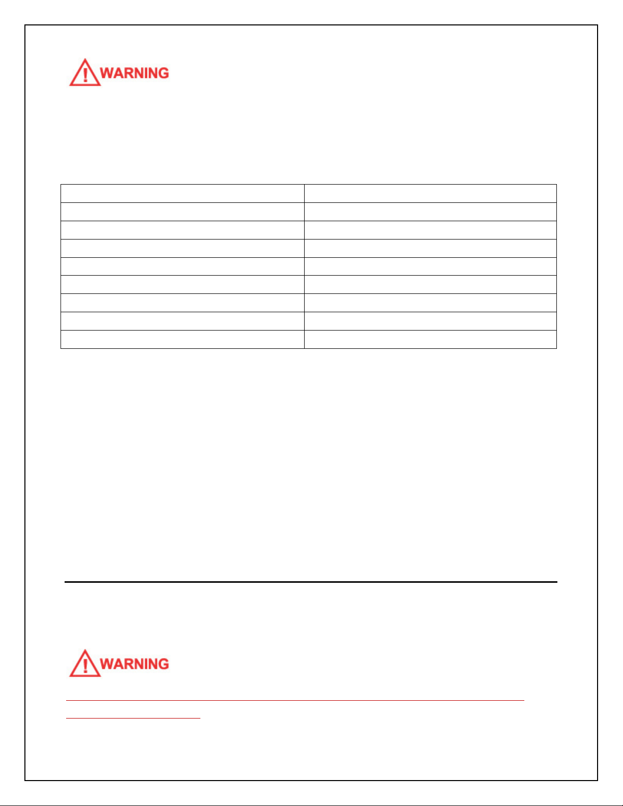
Minimum Water Pressure 20 PSI
Maximum Water Pressure 90 PSI*
Recommended Water Pressure 40-70 PSI
Water Temperature 36F to 100F (2 to 38C)
Minimum Air Temperature 32°F (0°C)**
pH Range 6.5*** to 8.5
Maximum Service Flow Rate 10 GPM (37 LPM)
Recommended Service Flow Rate <7 GPM (25 LPM)
Water Supply Treated City Water
* While the ecoPLUS™ system is built to withstand pressures exceeding 90 PSI if your water
pressure is greater than 70 PSI we recommend that you have a certified plumber install a
pressure reducing valve ahead of the ecoPLUS ™ system.
** The system cannot be subjected to freezing conditions or severe damage to the system
and your property could occur.
*** pH correction is strongly recommended where pH levels are less than 6.5 to prevent
damage to your plumbing system and to prevent the leaching of metals from copper and
brass plumbing components and solder in your home. Contact your dealer for
recommendations.
INSTALLATION
WE RECOMMEND THAT YOU READ THIS ENTIRE MANUAL BEFORE STARTING THE
ACTUAL INSTALLATION. WHILE WE STRONGLY RECOMMEND THAT A LICENSED
PLUMBER PERFORM ALL INSTALLATION WORK A MECHANICALLY-INCLINED

7
HOMEOWNER WITH SUITABLE PLUMBING KNOWLEDGE CAN INSTALL THIS SYSTEM.
IN ALL CASES IT IS CRITICAL THAT THE INSTALLATION BE DONE IN ACCORDANCE
WITH THESE INSTRUCTIONS AND ALL APPLICABLE PLUMBING AND ELECTRICAL
CODES. BE SURE TO OBTAIN ALL REQUIRED PERMITS. IF THESE INSTRUCTIONS AND
THE APPLICABLE CODES ARE IN CONFLICT THE RELEVANT PLUMBING/ELECTRICAL
CODE SHALL BE FOLLOWED. EQUIPMENT FAILURE PERSONAL INJURY OR PROPERTY
DAMAGE CAN RESULT IF THIS EQUIPMENT IS NOT INSTALLED PROPERLY.
KEEP THE MEDIA TANKS UPRIGHT AT ALL TIMES.
IF POSSIBLE WE RECOMMEND THAT PEX OR CPVC PIPE BE USED FOR ALL NEW
PLUMBING PIPE USED IN CONNECTION WITH THE INSTALLATION. THIS IS BECAUSE
NEW COPPER WATER LINES MAY RELEASE SOME COPPER IONS INTO THE WATER FOR
SEVERAL WEEKS AFTER INSTALLATION AND THESE IONS CAN HAVE A NEGATIVE
IMPACT ON THE ECOTAC™ MEDIA. TO FURTHER MINIMIZE ANY PROBLEMS WITH
COPPER AVOID APPLYING EXCESS FLUX ON THE INNER SURFACES OF THE PIPE AND
USE A LOW-CORROSIVITY WATER SOLUBLE FLUX LISTED UNDER THE ASTM B813
STANDARD. FOR HOMES WITH SIGNIFICANT NEWLY INSTALLED COPPER PIPES PRIOR
TO THE ECOTAC™ UNIT IT IS RECOMMENDED THAT INSTALLATION OF THE SYSTEM
BE POSTPONED FOR 3-4 WEEKS TO ALLOW A PROTECTIVE COATING TO FORM ON THE
NEW COPPER PIPES.
John Guest® Quick-Connect Style Fittings
Several steps in the installation use a special type of quick connect fitting made by
John Guest®. To connect a John Guest® fitting unlock the fitting by turning the collet
counter-clockwise until the fitting loosens. A small gap will open between the collet
and the back of the fitting. Push the tube firmly into the fitting as far as it will go. Turn
the collet clockwise until tight to secure the fitting. Pull out on the tube to ensure a
good connection has been made. The pipe can be removed from the fitting by
loosening the collet again and depressing the collar evenly while pulling outward on
the tube.

8
Step 1. – Pre-Installation Inspection
9
Inspect all of the components that you received with your unit. You should have received the
following:
1. ecoPlus™ Media Tank and Valve Head
2. Cartridge Filter Housing Cap
3. Cartridge Filter Housing Sump
4. Sediment Pre-Filter (shipped inside #3)
5. Mounting Bracket
6. Bypass Assembly
7. Flexible Stainless Steel Connectors (1” Quick Connect to 1” NPT)
8. Outlet Assembly
9. Inlet Assembly
10. Spanner Wrench
11. Small Parts Bag (8 Lag Bolts and 8 Washers)
12. ecoTAC™ Media Tank and Valve Head
13. Bridge Assembly
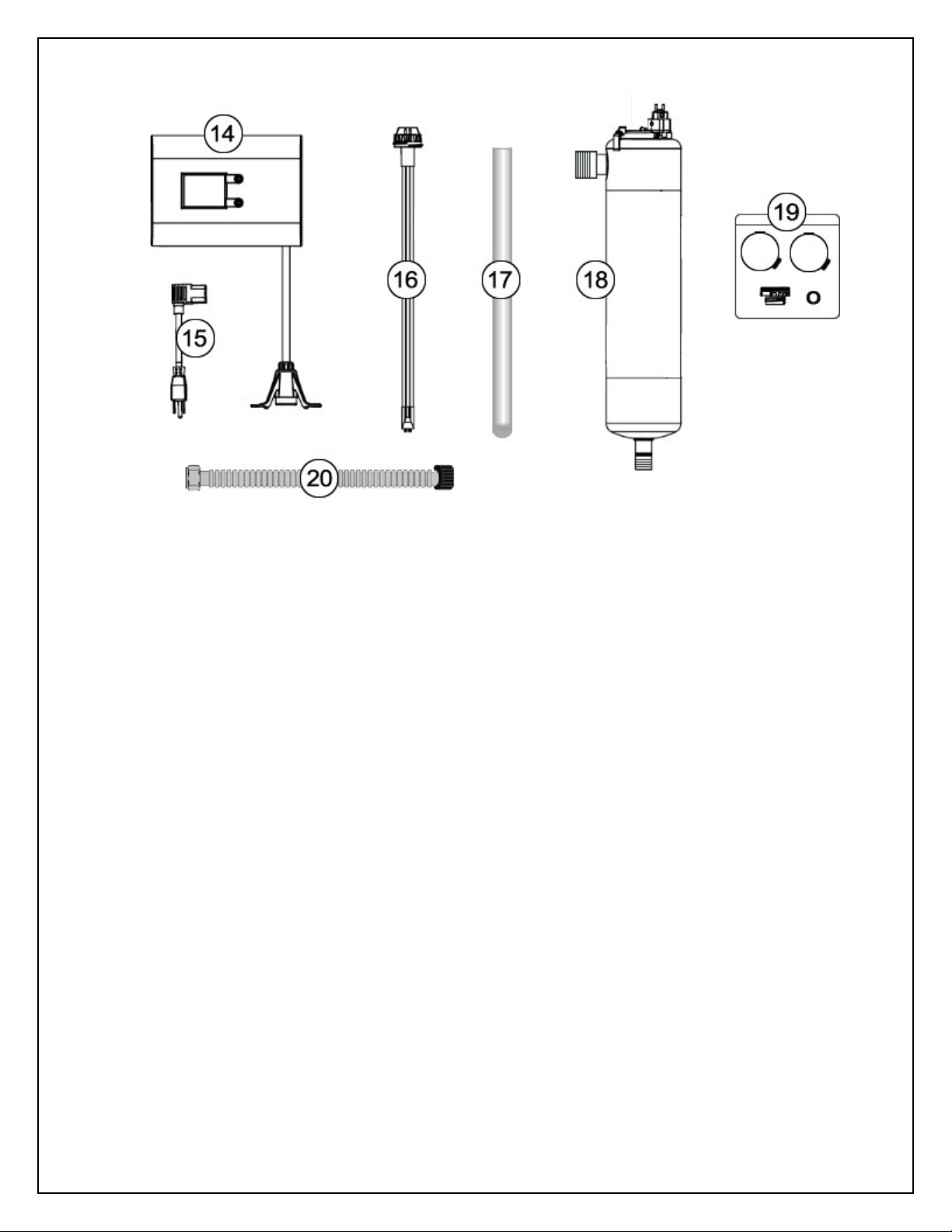
14. UV Controller
15. UV Power Cord
16. UV Lamp (do not touch the glass portion of the lamp!)
17. UV Sleeve (use gloves to handle the glass UV sleeve!)
18. UV Disinfection Chamber
19. UV Parts Bag (Contains: sleeve bolt sleeve o-ring and 2 chamber mounting clamps)
20. Flexible Stainless Steel Connector (3/4” NPT to 1” NPT)

Step 2. – Selecting an Installation Location
While exterior installation in warm climate areas is possible we strongly recommend interior
installation only. The system cannot be allowed to freeze or severe system damage could
occur. The system should not be exposed to rain and it should not be installed in direct
sunlight as long-term exposure to UV light could damage components of the system.
Select a location for installation of your water filter that is within close proximity to the main
incoming water line of the home. The location should have a firm level surface with enough
space for the unit itself and sufficient space surrounding the unit to facilitate maintenance.
The approximate minimum installation space required for
this model is:
40” Wide x 63” High x 20.5” Deep
In most cases the system should be installed after the
branch line(s) to exterior irrigation unless you want your
exterior faucets to deliver treated water. Depending on
the configuration of your plumbing system this is not
always possible. ecoPLUS™ should be installed after
your pressure tank and booster pump if applicable and
before your hot water heater.
IF YOU HAVE OTHER WATER TREATMENT EQUIPMENT YOU SHOULD DISCUSS THE
ORDER OF YOUR TREATMENT EQUIPMENT WITH YOUR DEALER PRIOR TO
INSTALLATION.
WHILE WATER LEAKS ARE VERY RARE AND UNEXPECTED YOUR WATER FILTER
SYSTEM SHOULD BE LOCATED NEXT TO A FLOOR DRAIN OR PROTECTED BY A WATER
LEAK DETECTION SYSTEM WITH AUTOMATIC SHUT-OFF VALVE TO PREVENT WATER
DAMAGE TO YOUR PROPERTY IN THE UNLIKELY EVENT OF A WATER LEAK.
RECOMMENDED WATER LEAK DETECTION SYSTEMS ARE AVAILABLE AT WWW.A-LEAK-
DETECTOR.COM.

11
Step 3. – Attach Mounting Bracket to Housing Cap
Using four (4) of the lag bolts and washers from the small parts bag attach the mounting
bracket to the cartridge filter housing cap as shown in the diagram below. The inlet of the
housing should be on the left.
Step 4. – Attach Housing Cap to Wall
Attach the cartridge filter housing cap and mounting bracket to your wall using the
remaining four (4) lag bolts and washers as shown below. The top of the mounting
bracket should be mounted EXACTLY 52 3/4 (52.75) inches off the floor. Use a carpenter’s
level to ensure that the bracket is mounted level to the floor. You will need to ensure that
there is adequate space on either side of the bracket to accommodate the system. You will
need approximately 9 inches on the left and 30 inches on the right.

12
If mounting to drywall we recommend that you use suitable wall anchors or that you mount
a small piece of 3/4 inch plywood to the wall first ensuring that it is securely screwed into
the wall studs. When the cartridge filter housing is full of water it is heavy so it is important
to ensure that the mounting will be strong enough to support the weight.
52 3/4 inches
from floor to
top of bracket
Approx. 9 inches
clearance to left
of bracket
Approx. 30 inches
clearance to right
of bracket

13
Step 5. – Install Cartridge Filter and Attach Sump
Remove the protective plastic wrap from the sediment pre-filter and place it in the cartridge
filter housing sump. At the bottom of the sump there is a raised portion in the middle
(standpipe) that will help center the filter in the housing. The standpipe will fit inside the hole
that runs through the middle of the filter cartridge. Check to make sure that the black O-ring
is seated properly in the grove at the top of the housing sump then screw the housing sump
containing the filter cartridge onto the cartridge filter housing cap. Hand tighten only - do not
use the spanner wrench. Do not over-tighten! Excessive force is not required to obtain a
good seal.
.
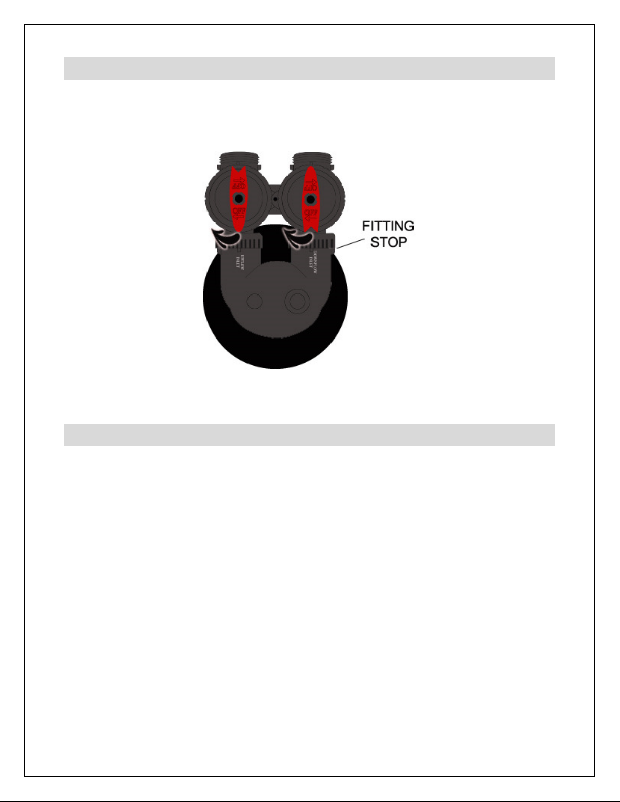
Step 6. – Connect Outlet Assembly to the ecoTAC™ Bypass Assembly
Thread the outlet assembly on to the outlet side of one of the bypass assemblies as shown.
This bypass assembly will be used on the ecoTAC™ system. Note the position of the fitting
stop. The threaded collar of the outlet adapter should thread right up to the fitting stop.
If there is a gap between the outlet adapter’s collar and the fitting stop it is not threaded on
far enough. Excessive force is not required to obtain a good seal. Do not over-tighten.

14
Step 7. – Connect the Bypass Assembly to the ecoTAC™ Valve Head
Thread the bypass assembly with the outlet assembly
on to the valve head on the ecoTAC™ media tank as
shown.
Again note the position of the fitting stops.
The threaded collars of the bypass assembly
should thread right up to the fitting stops with
no gap. Excessive force is not required to
obtain a good seal. Do not over-tighten.
*Please note: There is only a small amount of
ecoTAC™ media in the treatment tank. This is
completely normal and is necessary to allow the
required freeboard to permit the media bed to
completely fluidize during operation.
When water begins to flow into the bottom of the treatment tank the ecoTAC™ media is lifted
and disbursed throughout the treatment tank in a fluidized bed which enhances contact with
the calcium and magnesium ions in the water. A contact time of only a few seconds is
required for the treatment of up to 25 grains per gallon (approx. 425 ppm or mg/l) of
hardness. Since the system is operated in a fluidized upflow configuration the system will
not clog with sediment and no backwashing is required.

15
Step 8. – Connect the Inlet Assembly to the Housing Cap
Refer to John Guest® Quick-Connect Style Fittings above. First ensure the John
Guest® fitting is “unlocked.” Then push the elbow end of the inlet assembly on to the black
stem adapter as far as it will go.
Then turn the collet to securely lock the fitting.
16
Step 9. – Connect Bypass Assembly to ecoPLUS™ Valve Head
Connect the other bypass assembly to the ecoPLUS™ valve head in the same manner as
noted in Step 7.
Step 10. – Connect the ecoPLUS™ Tank to the Inlet Assembly
Position the ecoPLUS™ media tank to align the bypass assembly with the inlet assembly
attached to the cartridge filter housing cap.
Note that the black base of the media tank is not permanently attached to the rest of the
tank. If your tank appears to be crooked the base has likely been knocked out of alignment
during shipping. This can be correct by picking the tank up and tapping it on a hard surface
while holding it perpendicular to the floor. A few light taps will generally straighten it out.
Thread the inlet assembly on to the bypass assembly as shown in the same manner as
previous steps. There is a small amount of “play” in the bypass assembly to help address
minor misalignments. This is normal and will prevent undue stress on the components.
Make sure that the tank sits perpendicular to the floor.

17
(go to next page)

18
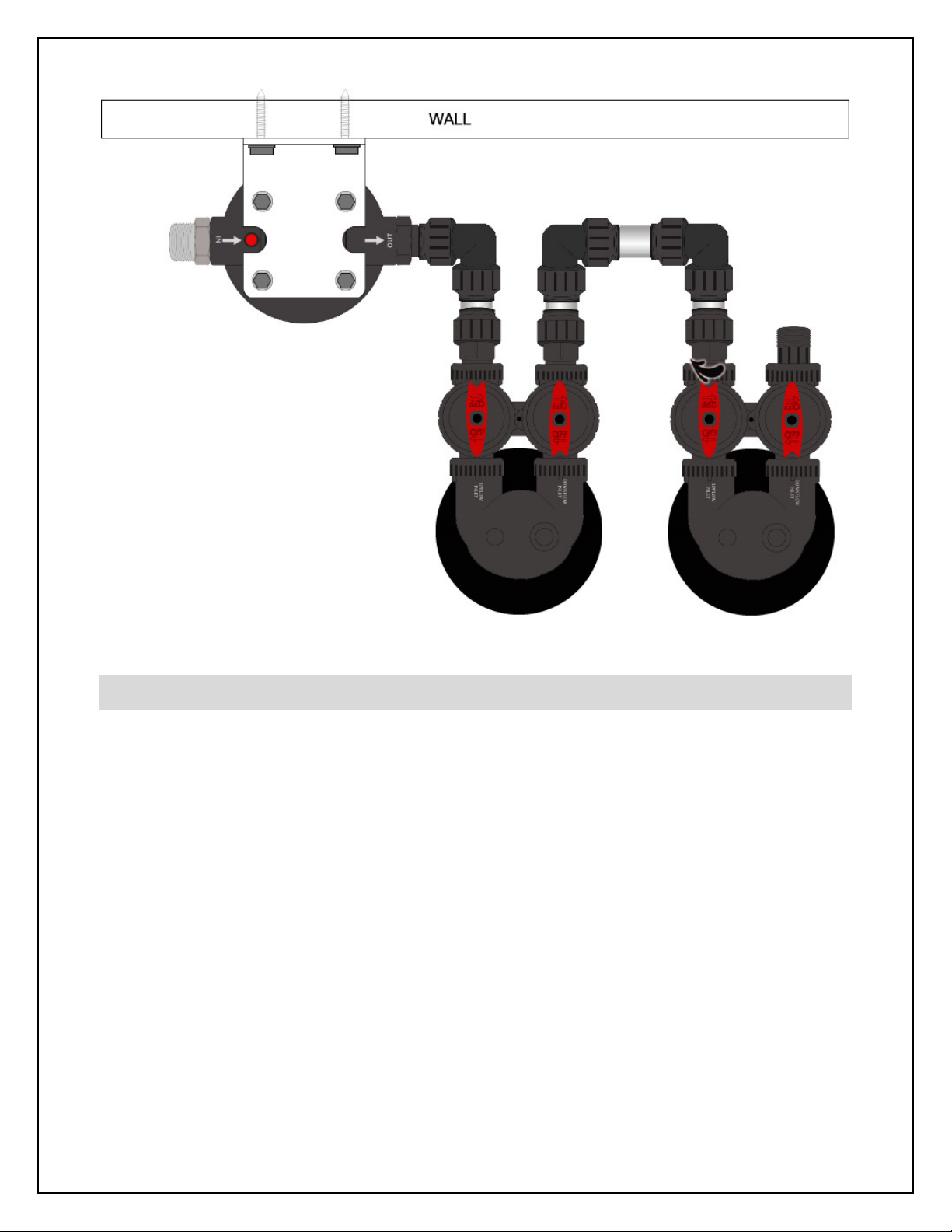
Step 11. – Connect Bridge Assembly to the ecoPLUS™ Bypass
Thread the bridge assembly on to the outlet side of the ecoPLUS™ bypass assembly as
shown.
Step 12. – Connect ecoTAC™ System
Confirm that the ecoTAC™ treatment tank is perpendicular to the floor and the
ecoPLUS™ treatment tank. The black base of the media tank is not permanently attached
to the rest of the tank. If your tank appears to be crooked the base has likely been knocked
out of alignment during shipping. This can be correct by picking the tank up and tapping it
on a hard surface while holding it perpendicular to the floor. A few light taps will generally
straighten it out.
Thread the bridge assembly on to the inlet side of the ecoTAC™ bypass assembly as shown.
19
Step 13. – Mount and Install UV Sterilizer
Locate the 3/4” NPT to 1” NPT flexible stainless steel connector. Connect the 1” end (black)
of the flexible stainless steel connector to the outlet assembly on the ecoTAC™ tank’s bypass.
It connects in the same way as a garden hose attaches to an outdoor faucet. Do not use
Teflon® tape or other thread sealants and do NOT over-tighten. Excessive force is not
required to obtain a good seal.
The other end (3/4” steel) of the flexible connector attaches to the inlet (bottom port) on the
UV disinfection chamber in the same manner. The flexible connector can be bent to reach
the UV chamber which should be mounted securely on the wall behind your ecoTAC™
media tank. The flexible connector is designed to be bent many times but not repeatedly
over and over. Doing so may reduce the structural integrity of the fitting.
Follow the instructions in the
Viqua UVMax D4 Premium Owner’s Manual Section 3.1
“Installing UV System”
to mount and install your UV sterilizer. Be sure that you install the

20
disinfection chamber such that the flexible connector can reach the inlet port at the bottom
of the chamber. Also ensure that there is at least 16” of clearance above the UV sterilizer to
allow for lamp and sleeve removal. Depending on the location of your outgoing water line
you can mount the outlet of the UV sterilizer so that its outlet port is on the right or left.
Step 14. – Turn Off Water & Electric Water Heaters
FAILURE TO FOLLOW THIS PROCEDURE COULD RESULT IN SERIOUS PERMANENT
DAMAGE TO THE HEATING ELEMENTS IN YOUR WATER HEATER.
If you have a conventional electric water heater or an on-demand (tankless) electric water
heater we highly recommend that you turn off the power to the heater while installing any
water treatment equipment. Turn off power to your water heater now.
Turn off the household main water shutoff valve. Open several plumbing fixtures inside the
home as well as the outside faucets to drain as much water out of the plumbing system as
possible.
Following completion of the entire installation restore the water flow by turning on the
household main water valve and allow all air to be purged from the plumbing system before
turning the power back on to your water heater.
Step 15. – Connect System to Inlet and Outlet Pipes
The 1 inch NPT stainless steel fitting on the inlet side of the cartridge filter housing cap
should be plumbed to your incoming water supply pipe.
If within reach this can be done with one of the flexible stainless steel connectors provided
with your system if you have 1 inch PEX copper or CPVC water lines. The non-threaded end
of the connector can be connected directly to 1 inch diameter PEX copper or CPVC tubing
by pushing the fitting on to the tubing as far as it will go. Unlike the other John Guest®
fittings used previously in the installation there is no locking collet. The black end of the
flexible stainless steel connector threads onto the stainless steel fitting in the same way as
you would attach a garden hose to an outdoor faucet. Do not use Teflon® tape of other
Table of contents
Other Ecoplus Water Filtration System manuals


Popular Water Filtration System manuals by other brands

Yamato
Yamato WG 1000 instruction manual

Master
Master MBA-MM-1040 Installation and operation manual

Watts
Watts GTS450S Installation, operation & maintenance manual

EM-Technik
EM-Technik 7F400 Assembly and operation instructions

Pure Pressure
Pure Pressure Axis Service manual

Vulcan-Hart
Vulcan-Hart MF-1 Specifications


Fernox
Fernox MKIII user guide

AquaScape
AquaScape 77011 installation instructions

Judo
Judo EASY FILT-BP Installation and operating instructions

Weh
Weh TSF2 H2 operating instructions

Oase
Oase Aquarius Eco Expert 22000 operating instructions

TCi
TCi HarmonicGuard Series Installation, operation and maintenance manual