Ecoplus ecoPLUS EP-600-UV Troubleshooting guide

OWNER’S MANUAL & INSTALLATION GUIDE
ecoPLUS™ EP-600-UV
PLEASE READ THIS MANUAL CAREFULLY BEFORE
ATTEMPTING INSTALLATION FAILURE TO FOLLOW THESE
INSTRUCTIONS MAY AFFECT THE PERFORMANCE OF YOUR
SYSTEM, VOID YOUR WARRANTY, AND RESULT IN
PROPERTY DAMAGE
t
2
Congratulations on the purchase of your ecoPLUS™ Series premium whole house water
filtration system
ecoPLUS™ EP-600-UV is specifically engineered to treat city water by removing chlorine
chloramine disinfection by-products bad tastes and odors and other trace contaminants
including VOCs pesticides herbicides organic chemicals lead and more. It also provides
enhanced protection against bacteria viruses and other microorganisms. ecoPLUS™
delivers refreshing great tasting drinking water protects your skin and hair from the
damaging effects of these contaminants and gives you peace-of-mind.
To get maximum performance from your ecoPLUS™ system we encourage to read this
manual in its entirely before installation and operation of your filter.
IMPORTANT SAFETY SYMBOLS
Hazards or unsafe practices that may result in personal injury
and/or severe property damage.
Hazards or unsafe practices that may cause operational
problems with your water treatment system.

3
Table of Contents:
GENERAL WARNINGS ………………………………………………………………………………………………………… 4
OPERATING CONDITIONS …………………………………………………………………………………………….…... 5
INSTALLATION ………………………………………………………………………………………………………….…..…..….. 6
Step 1 – Pre-Installation Inspection ……………………………………………………………..……… 7
Step 2 – Selecting an Installation Location ………………………………………………..…..... 8
Step 3 – Attach Mounting Bracket to Housing Cap ………………………………..……… 10
Step 4 – Attach Housing Cap to Wall …………………………………………………………………. 11
Step 5 – Install Cartridge Filter and Attach Sump ……………………………………….…… 10
Step 6 – Connect Outlet Assembly to the Bypass Assembly ……………………..…. 11
Step 7 – Connect the Bypass Assembly to Valve Head ……………………………..….. 12
Step 8 – Connect the Inlet Assembly to the Housing Cap ………………………..…… 12
Step 9 – Connect the Bypass to the Inlet Assembly …………………………………..…….. 13
Step 10 – Mount & Install UV Sterilizer …………………………………………………………………. 15
Step 11 – Turn off the Water & Electric Water Heaters ………………………………….… 15
Step 12 – Connect the System to Inlet and Outlet Pipes ………………………………… 16
Step 13 – Leak Testing and Media Conditioning ………………………………………......…. 17
Step 14 – System Disinfection ………………………………………………………………………………… 18
TROUBLESHOOTING ………………………………………………………………………….……………………….…..…… 19
MAINTENANCE ………………………………………………………………………………….…………………….…..….……. 20
VALIDATIONS ……………………………………………………………………………………..…………………….…..….……. 23
SATISFACTION GUARANTEE ……………………………………………………….…………………….…..….……. 24
WARRANTY INFORMATION …………………………………………………………………………………..……..…… 24

4
GENERAL WARNINGS
Do not allow children or pets to play on or around the water filter.
Do not install or store this filter system where it will be exposed to freezing temperatures.
Do not tamper with controls.
Do not repair replace or attempt to service any part of the system unless specifically
instructed to in this manual and you have the understanding tools and skills necessary to
carry out the procedure.
Packing materials can be dangerous to children. Keep all packing material (plastic bags
polystyrene boxes etc.) well out of children’s reach.
Individual components of this water treatment system and the installed system are heavy.
Precautions should be taken to prevent personal injury or strain. Do not move heavy
components without assistance if you are not physically capable of safely carrying out the
procedure.
If the water treatment system is to be left unattended for an extended period of time
(vacation etc.) we strongly recommend that you turn off the water supply to the system or
the whole house while you are away.
If your water pipes are metal (galvanized or copper) they may be used to ground electrical
systems appliances or your phone line. If this is the case be sure to install regulation
ground clamps to the metal pipe on each side of the filter system and connect a jumper wire
between the 2 clamps (#4 gauge solid copper wire recommended). Consult a certified
electrician or plumber if you are unsure.
This water treatment system is designed specifically for the treatment of chlorinated city
water supplies. ecoPLUS™ is not intended to be used to treat water from private wells or
private surface water sources.
5
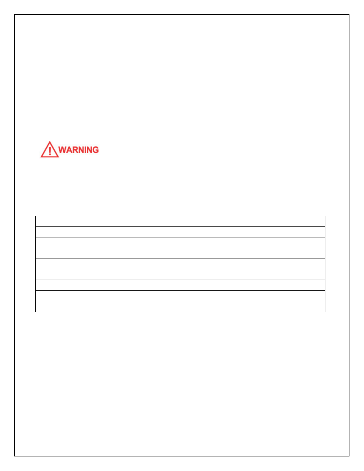
OPERATING CONDITIONS
The following chart provides guidance on the conditions required for successful operation of
your ecoPLUS™ system.
This water treatment system is designed specifically for the treatment of chlorinated city
water supplies ecoPLUS™ is not intended to be used to treat water from private wells or
private surface water sources If you are unsure of the status of your water supply please
contact your dealer for assistance.
USE OF THIS EQUIPMENT OUTSIDE OF THESE OPERATING CONDITIONS MAY
ADVERSELY AFFECT THE PERFORMANCE OF YOUR SYSTEM, RESULT IN SYSTEM
DAMAGE INCLUDING WATER LEAKS AND CORRESPONDING PROPERTY DAMAGE, AND
MAY VOID YOUR WARRANTY
Minimum Water Pressure 20 PSI
Maximum Water Pressure 90 PSI*
Recommended Water Pressure 40-70 PSI
Water Temperature 36F to 100F (2 to 38C)
Minimum Air Temperature 32°F (0°C)**
pH Range 6.5*** to 8.5
Maximum Service Flow Rate 10 GPM (37 LPM)
Recommended Service Flow Rate <7 GPM (25 LPM)
Water Supply Treated City Water
* While the ecoPLUS™ system is built to withstand pressures exceeding 90 PSI if your water
pressure is greater than 70 PSI we recommend that you have a certified plumber install a
pressure reducing valve ahead of the ecoPLUS ™ system.
** The system cannot be subjected to freezing conditions or severe damage to the system
and your property could occur.
*** pH correction is strongly recommended where pH levels are less than 6.5 to prevent
damage to your plumbing system and to prevent the leaching of metals from copper and
brass plumbing components and solder in your home. Contact your dealer for
recommendations.

6
INSTALLATION
WE RECOMMEND THAT YOU READ THIS ENTIRE MANUAL BEFORE STARTING THE
ACTUAL INSTALLATION THE VIQUA UVMAX D4 PREMIUM (UV STERILIZER) OWNER’S
MANUAL IS INTEGRAL TO THIS SYSTEM AND SHOULD BE READ IN DETAIL PRIOR TO
INSTALLATION THIS MANUAL IS ENCLOSED WITH YOUR UV STERILIZER WHILE WE
STRONGLY RECOMMEND THAT A LICENSED PLUMBER PERFORM ALL INSTALLATION
WORK, A MECHANICALLY-INCLINED HOMEOWNER WITH SUITABLE PLUMBING
KNOWLEDGE CAN INSTALL THIS SYSTEM IN ALL CASES, IT IS CRITICAL THAT THE
INSTALLATION BE DONE IN ACCORDANCE WITH THESE INSTRUCTIONS AND ALL
APPLICABLE PLUMBING AND ELECTRICAL CODES BE SURE TO OBTAIN ALL REQUIRED
PERMITS IF THESE INSTRUCTIONS AND THE APPLICABLE CODES ARE IN CONFLICT,
THE RELEVANT PLUMBING/ELECTRICAL CODE SHALL BE FOLLOWED EQUIPMENT
FAILURE, PERSONAL INJURY, OR PROPERTY DAMAGE CAN RESULT IF THIS EQUIPMENT
IS NOT INSTALLED PROPERLY
KEEP THE MEDIA TANK UPRIGHT AT ALL TIMES
John Guest® Quick-Connect Style Fittings
Several steps in the installation use a special type of quick connect fitting made by
John Guest®. To connect a John Guest® fitting unlock the fitting by turning the collet
counter-clockwise until the fitting loosens. A small gap will open between the collet
and the back of the fitting. Push the tube firmly into the fitting as far as it will go. Turn
the collet clockwise until tight to secure the fitting. Pull out on the tube to ensure a
good connection has been made. The pipe can be removed from the fitting by
loosening the collet again and depressing the collar evenly while pulling outward on
the tube.
7
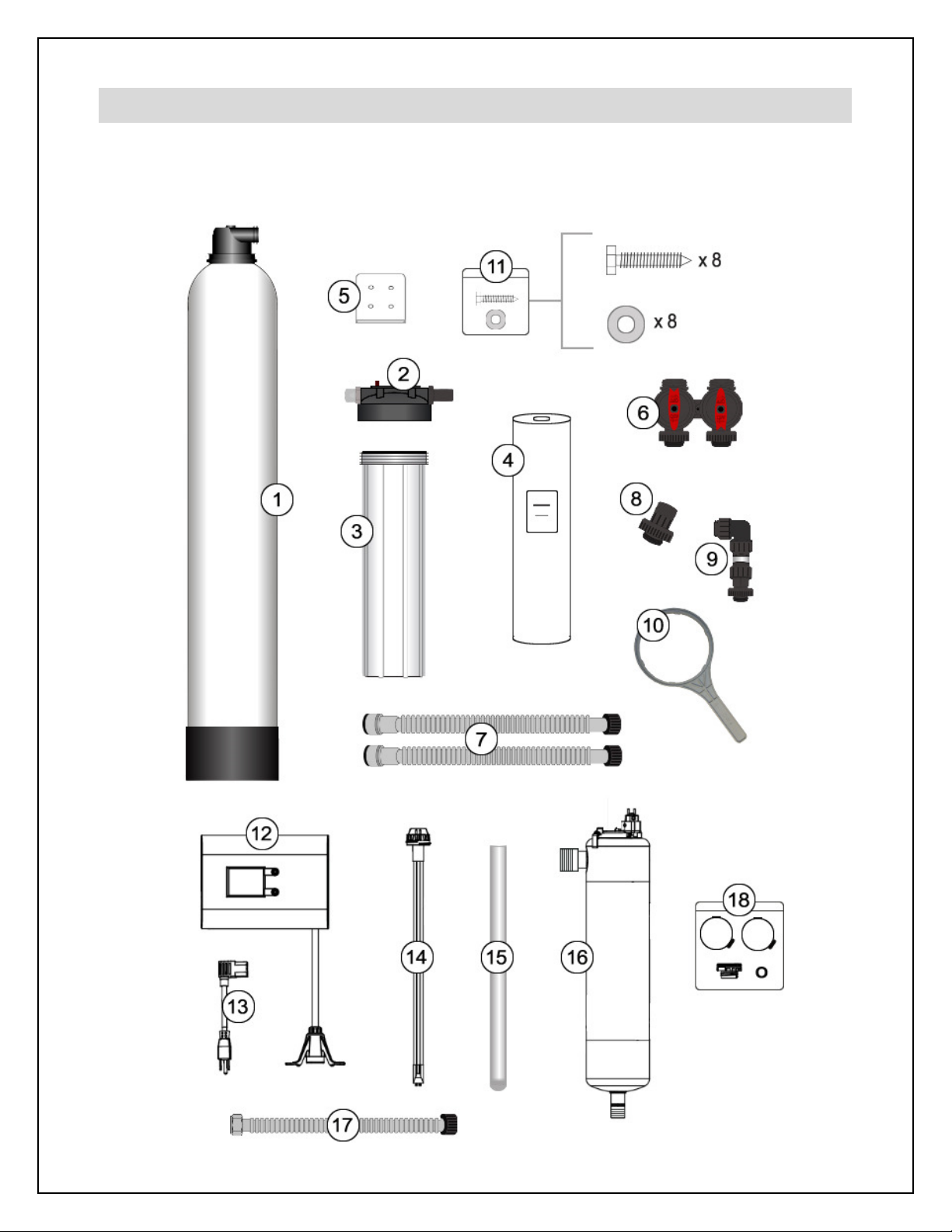
Step 1 – Pre-Installation Inspection
Inspect all of the components that you received with your unit. You should have received the
following:

8
1. ecoPlus™ Media Tank and Valve Head
2. Cartridge Filter Housing Cap
3. Cartridge Filter Housing Sump
4. Sediment Pre-Filter (shipped inside #3)
5. Mounting Bracket
6. Bypass Assembly
7. Flexible Stainless Steel Connectors (1” Quick Connect to 1” NPT)
8. Outlet Assembly
9. Inlet Assembly
10. Spanner Wrench
11. Small Parts Bag (Contains: 8 Lag Bolts and 8 Washers)
12. UV Controller
13 UV Power Cord
14. UV Lamp (do not touch the glass portion of the lamp!)
15. UV Sleeve (use gloves to handle the glass UV sleeve!)
16. UV Disinfection Chamber
17. Flexible Stainless Steel Connector (3/4” NPT to 1” NPT)
18. UV Parts Bag (Contains: sleeve bolt sleeve o-ring and 2 chamber mounting clamps)
Step 2 – Selecting an Installation Location
While exterior installation in warm climate areas is possible we strongly recommend interior
installation only. The system cannot be allowed to freeze or severe system damage could
occur. The system should not be exposed to rain and it should not be installed in direct
sunlight as long-term exposure to UV light could damage
components of the system.
Select a location for installation of your water filter that is
within close proximity to the main incoming water line of
the home. The location should have a firm level surface
with enough space for the unit itself and sufficient space
surrounding the unit to facilitate maintenance.
The approximate minimum installation space required for
this model is:
32 5” Wide x 63” High x 20 5” Deep
In most cases the system should be installed after the

9
branch line(s) to exterior irrigation unless you want your exterior faucets to deliver treated
water. Depending on the configuration of your plumbing system this is not always possible.
ecoPLUS™ should be installed after your pressure tank and booster pump if applicable and
before your hot water heater.
IF YOU HAVE OTHER WATER TREATMENT EQUIPMENT,
YOU SHOULD DISCUSS THE ORDER OF YOUR TREATMENT EQUIPMENT WITH YOUR
DEALER PRIOR TO INSTALLATION
WHILE WATER LEAKS ARE VERY RARE AND UNEXPECTED, YOUR WATER FILTER
SYSTEM SHOULD BE LOCATED NEXT TO A FLOOR DRAIN OR PROTECTED BY A WATER
LEAK DETECTION SYSTEM WITH AUTOMATIC SHUT-OFF VALVE TO PREVENT WATER
DAMAGE TO YOUR PROPERTY IN THE UNLIKELY EVENT OF A WATER LEAK
RECOMMENDED WATER LEAK DETECTION SYSTEMS ARE AVAILABLE AT WWW A-LEAK-
DETECTOR COM
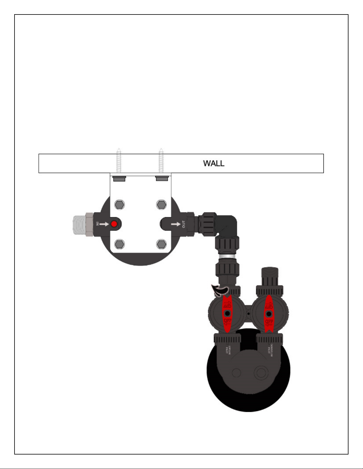
Step 3 – Attach Mounting Bracket to Housing Cap
Using four (4) of the lag bolts and washers from the small parts bag attach the mounting
bracket to the cartridge filter housing cap as shown in the diagram below. The inlet of the
housing should be on the left.

10
Step 4 – Attach Housing Cap to Wall
Attach the cartridge filter housing cap and mounting bracket to your wall using the
remaining four (4) lag bolts and washers as shown below. The top of the mounting
bracket should be mounted EXACTLY 52 3/4 (52 75) inches off the floor Use a carpenter’s
52 3/4
inches from
floor to top of
bracket
9 inches
clearance to
left of bracket
19 inches
clearance to
right
of bracket

11
level to ensure that the bracket is mounted level to the floor. You will need to ensure that
there is adequate space on either side of the bracket to accommodate the system. Ideally
you should have approximately 9-12 inches on the left and 19-22 inches on the right
although installation in a smaller space is possible.
If mounting to drywall we recommend that you use suitable wall anchors or that you mount
a small piece of 3/4 inch plywood to the wall first ensuring that it is securely screwed into
the wall studs. When the cartridge filter housing is full of water it is heavy so it is important
to ensure that the mounting will be strong enough to support the weight.
Step 5 – Install Cartridge Filter and Attach Sump
Remove the protective plastic wrap from the sediment pre-filter and place it in the cartridge
filter housing sump. At the bottom of the sump there is a raised portion in the middle
(standpipe) that will help center the filter in the housing. The standpipe will fit inside the hole
that runs through the middle of the filter cartridge. Check to make sure that the black O-ring
is seated properly in the grove at the top of the housing sump then screw the housing sump
containing the filter cartridge onto the cartridge filter housing cap. Hand tighten only - do not
use the spanner wrench. Do not over-tighten! Excessive force is not required to obtain a
good seal.
.
Step 6 – Connect Outlet Assembly to the Bypass Assembly
Thread the outlet assembly on to the outlet side of the bypass assembly as shown. Note the
position of the fitting stop. The threaded collar of the outlet adapter should thread right up to
the fitting stop.

12
If there is a gap between the outlet adapter’s collar and the fitting stop it is not threaded on
far enough. Excessive force is not required to obtain a good seal. Do not over-tighten.
Step 7 – Connect the Bypass Assembly to Valve Head
Thread the bypass assembly on to the valve
head on the ecoPlus™ media tank as shown.
Again note the position of the fitting stops.
The threaded collars of the bypass assembly
should thread right up to the fitting stops with
no gap. Excessive force is not required to
obtain a good seal. Do not over-tighten.
Step 8 – Connect the Inlet
Assembly to the Housing Cap
Refer to John Guest® Quick-Connect Style
Fittings above. First ensure the John Guest®
fitting is “unlocked.” Then push the elbow end
of the inlet assembly on to the black stem adapter as far as it will go.

13
Then turn the collet to securely lock the fitting.
Step 9 – Connect Bypass to Inlet Assembly
Position the ecoPLUS™ media tank to align the bypass assembly with the inlet assembly
attached to the cartridge filter housing cap.
14
Note that the black base of the media tank is not permanently attached to the rest of the
tank. If your tank appears to be crooked the base has likely been knocked out of alignment
during shipping. This can be correct by picking the tank up and tapping it on a hard surface
while holding it perpendicular to the floor. A few light taps will generally straighten it out.
Thread the inlet assembly on to the bypass assembly as shown in the same manner as
previous steps. There is a small amount of “play” in the bypass assembly to help address
minor misalignments. This is normal and will prevent undue stress on the components.
Make sure that the tank sits perpendicular to the floor.
15
Step 10 – Mount and Install UV Sterilizer
Locate the 3/4” NPT to 1” NPT flexible stainless steel connector. Connect the 1” end (black)
of the flexible stainless steel connector to the outlet assembly on the ecoPLUS™ tank’s
bypass. It connects in the same way as a garden hose attaches to an outdoor faucet. Do
not use Teflon® tape or other thread sealants and do NOT over-tighten. Excessive force is
not required to obtain a good seal.
The other end (3/4” steel) of the flexible connector attaches to the inlet (bottom port) on the
UV disinfection chamber in the same manner. The flexible connector can be bent to reach
the UV chamber which should be mounted securely on the wall behind your ecoPLUS™
media tank. The flexible connector is designed to be bent many times but not repeatedly
over and over. Doing so may reduce the structural integrity of the fitting.
Follow the instructions in the
Viqua UVMax D4 Premium Owner’s Manual Section 3 1
“Installing UV System”
to mount and install your UV sterilizer. Be sure that you install the
disinfection chamber such that the flexible connector can reach the inlet port at the bottom
of the chamber. Also ensure that there is at least 16” of clearance above the UV sterilizer to
allow for lamp and sleeve removal. Depending on the location of your outgoing water line
you can mount the outlet of the UV sterilizer so that its outlet port is on the right or left.
Step 11 – Turn Off Water & Electric Water Heaters
FAILURE TO FOLLOW THIS PROCEDURE COULD RESULT IN SERIOUS, PERMANENT
DAMAGE TO THE HEATING ELEMENTS IN YOUR WATER HEATER
If you have a conventional electric water heater or an on-demand (tankless) electric water
heater we highly recommend that you turn off the power to the heater while installing any
water treatment equipment. Turn off power to your water heater now.
Turn off the household main water shutoff valve. Open several plumbing fixtures inside the
home as well as the outside faucets to drain as much water out of the plumbing system as
possible.

16
Following completion of the entire installation restore the water flow by turning on the
household main water valve and allow all air to be purged from the plumbing system before
turning the power back on to your water heater.
Step 12 – Connect System to Inlet and Outlet Pipes
The 1 inch NPT stainless steel fitting on the inlet side of the cartridge filter housing cap
should be plumbed to your incoming water supply pipe.
If within reach this can be done with one of the 1” Quick Connect to 1” NPT flexible stainless
steel connectors provided with your system if you have 1 inch PEX copper or CPVC water
lines. The non-threaded end of the connector can be connected directly to 1 inch diameter
PEX copper or CPVC tubing by pushing the fitting on to the tubing as far as it will go. Unlike
the other John Guest® fittings used previously in the installation there is no locking collet.
The black end of the flexible stainless steel connector threads onto the stainless steel fitting
in the same way as you would attach a garden hose to an outdoor faucet. Do not use
Teflon® tape or other thread sealants and do NOT over-tighten. Excessive force is not
required to obtain a good seal.
The flexible connector can be bent to reach your incoming water line. It is designed to be
bent a many times but not repeatedly over and over. Doing so may reduce the structural
integrity of the fitting.
Alternatively you can make the plumbing connection between your stainless steel fitting on
the cartridge filter housing cap and your incoming water line with suitable pipe tubing and
fittings from your plumbing supply store.
Connect the outlet port on the UV sterilizer to your outgoing water pipe in the same manner
using the other flexible stainless steel connector provided or your own pipe tubing and
fittings if preferred or required.
If desired you can plumb in shut-off valves before and after the system and/or a bypass loop
that can provide untreated water to your home during servicing.

17
Common Installation Configuration:
Step 13 – Leak Testing and Media Conditioning
Ensure that the bypass valve is in the “bypass” position (see next page for diagram).
Turn on the main water supply. Open a cold water tap nearby and let the water run for a few
minutes until the system is free of foreign material and air that may have resulted from the
installation. Once the water is running clear and free of air close the water tap.

18
INSPECT ALL PLUMBING CONNECTIONS AND THE INTERFACE BETWEEN THE MEDIA
TANK AND ITS VALVE HEAD FOR LEAKS AND REPAIR ANY LEAKS FOUND BEFORE
PROCEEDING
IN PARTICULAR, INSPECT THE BUSHING ON THE OUTLET OF THE UV STERILZER
WHILE THIS PART IS FACTORY INSTALLED, IT IS NOT LEAK TESTED DURING
PRODUCTION IF YOU GET A LEAK FROM THIS FITTING, TIGHTEN IT ACCORDINGLY
AND RE-TEST
Media Pre-Soak
Open the bypass valve to the “service” position. Slowly open a nearby faucet allowing a
slow flow of water. It may take several minutes for the flow of water to arrive as the media
tank will be slowly filling with water. During this time air will escape from the faucet. It is
normal for the water to be highly discolored at this stage as carbon fines are purged from
the system. Continue until all air is purged. Then turn off the faucet and allow the media to
soak for a minimum of twenty-four (24) hours. Set the bypass valve to the “bypass” position
so you can use water during the media pre-soak process. Run the nearby faucet until the
water runs clear.
It is now safe to turn the electricity back on to your water heater.
Final Media Rinse
After the media has soaked for at least twenty-four (24) hours set the bypass valve to the
“service” position again and open a nearby faucet and allow a slow flow of water to run for 5
minutes. Thereafter gradually increase the flow rate until a moderate flow of water is
achieved and run at this level for at least another 10 minutes. It is normal for the water to be
discolored at this stage as carbon fines are purged from the system. Gradually increase the
flow rate a little more and run the water until it is completely clear. If you notice a significant
19
decline in flow rate to the faucet at any point in the process shut the water off and wait 10
minutes then resume the process where you left off.
Step 14 – System Disinfection
Place the ecoPLUS™ bypass valve in the “bypass” position. Follow the instructions in the
Viqua UVMax D4 Premium Owner’s Manual Section 3 2 “Disinfection Procedure”
to
disinfect the UV sterilizer and downstream plumbing.
Familiarize yourself with the UV control panel functions by reading
Viqua UVMax D4
Premium Owner’s Manual Section 4
Congratulations!
Your system is now ready to provide treated water to your home!
We recommend that you limit the use of high flow rate applications for the first few days of
operation to allow your carbon media to be fully conditioned and saturated. It is common
and normal for some carbon dust to be released from the filter in the first few days of
operation. This carbon is harmless and will generally go away within about a week.
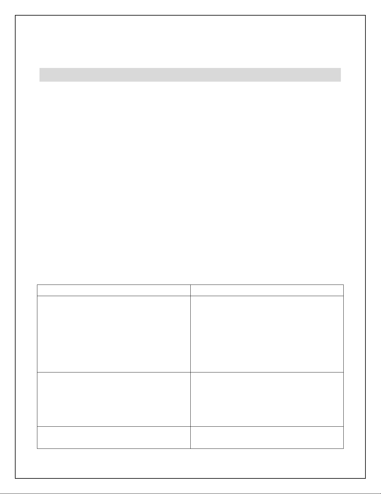
TROUBLESHOOTING
Problem Solution
Reduced water pressure and/or flow rate
after initial installation.
Limit high flow rate demands during the first
few days of operation to allow time for the
media bed to condition and saturate with
water. If significant pressure loss is
experienced turn off water wait 10 minutes
and try again. Ensure flow rate demands do
not exceed capacity specifications.
Reduced water pressure and/or flow rate at
other times.
The sediment pre-filter may need to be
replaced. In most cases it should be
replaced every 9 to 12 months. Ensure flow
rate demands do not exceed capacity
specifications.
Treated water is discolored. During the initial start-up and for roughly the
first week after installation you may notice

20
small black specs or a grey/black
discoloration caused by carbon fines (dust).
This is normal and will go away on its own.
The carbon dust is not harmful. Air trapped
in your water lines after installation can
sometimes cause the water to appear milky.
If you fill a glass of water and it appears milky
at first but clears relatively quickly this is
likely due to micro air bubbles. This situation
is harmless and will go away as the air is
completely purged out of your system.
Troubleshooting information related to the UV sterilizer can be found in the
Viqua UVMax D4
Premium Owner’s Manual Section 6
MAINTENANCE
THE SYSTEM MUST BE DEPRESSURIZED BEFORE REMOVING ANY COMPONENTS FOR
SERVICING TO DEPRESSURIZE THE SYSTEM, CLOSE YOUR MAIN WATER SHUT-OFF
VALVE AND RUN WATER AT SEVERAL FAUCETS
Cleaning
The outside of your system including cartridge filter housing and media tank can be
washed with a mild soap and water if desired. Do NOT use strong cleaners as they may
cause damage to the system components.
Sediment Pre-filter
The sediment pre-filter should be replaced every 9 to 12 months or as necessary to provide
satisfactory water pressure to your home. The life of the filter will depend on the amount of
sediment in your feed water supply. If you notice reduced water pressure it is likely that your
pre-filter needs to be replaced.
The replacement filter cartridge for your system is: Hydronix SDC-45-2005
Table of contents
Other Ecoplus Water Filtration System manuals


