EcoPowerSupplies 40 kVA User manual

51
INTRODUCTION
Thank you for choosing our product.
Our company is specialised in the design, development and production of Uninterruptible Power Supplies (UPS)
The UPS described in this manual is a high quality, meticulously designed product, built to guarantee the best performance.
This manual contains detailed instructions on how to use and install this product.
For information on how to use this equipment and obtain the best performance, this manual must be carefully kept
near the UPS and it must be READ BEFORE OPERATING IT.
© Reproduction of this manual or any portion thereof without the manufacturer’s consent is prohibited.
The manufacturer reserves the right to revise or make improvements to its product at any time without prior notice.

52
CONTENTS
OVERVIEW 54
UPS 30 –40 54
FRONT VIEWS OF THE UPS 55
VIEWS OF THE UPS CONNECTIONS 57
REAR VIEW OF THE UPS 58
VIEW OF THE CONTROL PANEL 59
SEPARATE BYPASS INPUT (OPTIONAL) 60
INSTALLATION 61
STORAGE OF THE UPS 61
PREPARATION FOR INSTALLATION 61
PRELIMINARY INFORMATION 61
ELECTROMAGNETIC COMPATIBILITY 62
INSTALLATION ENVIRONMENT 62
REMOVING THE UPS FROM THE PALLET 63
PRELIMINARY CHECK OF CONTENTS 64
POSITIONING THE UPS 64
OPERATIONS TO ACCESS THE TERMINALS OF THE UPS 64
ELECTRICAL CONNECTIONS 65
DIAGRAMS OF CONNECTIONS TO THE ELECTRICAL SYSTEM 65
UPS INTERNAL PROTECTIONS 68
EXTERNAL PROTECTION DEVICES 69
CROSS SECTION OF THE CABLES 70
CONNECTIONS 70
CONNECTIONS OF THE MODEL WITH SEPARATE BYPASS 71
R.E.P.O. 71
EXTERNAL SYNC 71
REMOTE MAINTENANCE BYPASS CONNECTION 72
CONNECTING THE UPS TO THE BATTERY BOX (OPTIONAL) 73
SETTING THE NOMINAL BATTERY CAPACITY –SOFTWARE CONFIGURATION 74
EXTERNAL TEMPERATURE PROBE 74
REMOTE SYNOPTIC PANEL (OPTIONAL) 74
USE 75
DESCRIPTION 75

53
PRELIMINARY OPERATIONS AND FIRST START-UP 76
MAINS START-UP 78
BATTERY START-UP 78
SWITCHING OFF THE UPS 78
GRAPHIC DISPLAY 79
MENU DISPLAY 80
OPERATING MODE 81
MAINTENANCE BYPASS (SWMB) 81
REDUNDANT AUXILIARY POWER SUPPLY FOR AUTOMATIC BYPASS 82
AUXILIARY “POWER SHARE”AND “POWER OUT”SOCKETS (OPTIONALS) 82
POWER WALK-IN 82
POWER REDUCTION FOR 200/208V PHASE-NEUTRAL LOADS 82
CONFIGURING THE UPS 83
COMMUNICATION PORTS 85
RS232 AND USB CONNECTORS 85
COMMUNICATION SLOT 85
AS400 PORT 86
BUZZER 87
SOFTWARE 88
MONITORING AND CONTROL SOFTWARE 88
CONFIGURATION SOFTWARE 88
TROUBLESHOOTING 89
STATUS /ALARM CODES 93
TECHNICAL DATA 97

54
OVERVIEW
UPS 30 -40
The UPSs in the 30 – 40 series have been designed using state-of-the-art technology, in order to ensure the best performance
for the user. The use of the new control boards based on microprocessor architecture (DSP + μP inside), together with the
adoption of specific circuit solutions that use last-generation components, have allowed to reach high performances such as:
¾ZERO IMPACT SOURCE: ensures low input distortion, a power factor close to 1, and maximum generator set
compatibility.
¾BATTERY CARE SYSTEM: allows a customised management for different battery types and their continuous
monitoring, therefore enhancing battery efficiency and durability.
¾SMART INVERTER: guarantees an extraordinary efficiency even at a low-load percentage. Moreover, it ensures a
stable low-distortion output tension even in extreme operating conditions.
Thanks to these and other features, and thanks to its ease of use, the 30 – 40 series presents itself as a reference point among
three-phase UPSs.

55
FRONT VIEWS OF THE UPS
Control panel with graphic display
Wheels for moving the UPS
Front door with lock Brake rod
Ventilation grid

56
Slot for auxiliary communication board
From the left:
Input isolator /Separate bypass isolator (optional) /
Manual bypass isolator / Output isolator
From the left:
Battery start button (COLD START) / R.E.P.O.
(Remote Emergency Power Off) connector / Contact
holder for AS400 / USB communication port / RS232
communication port
Terminal cover
Battery fuse holder isolator
57
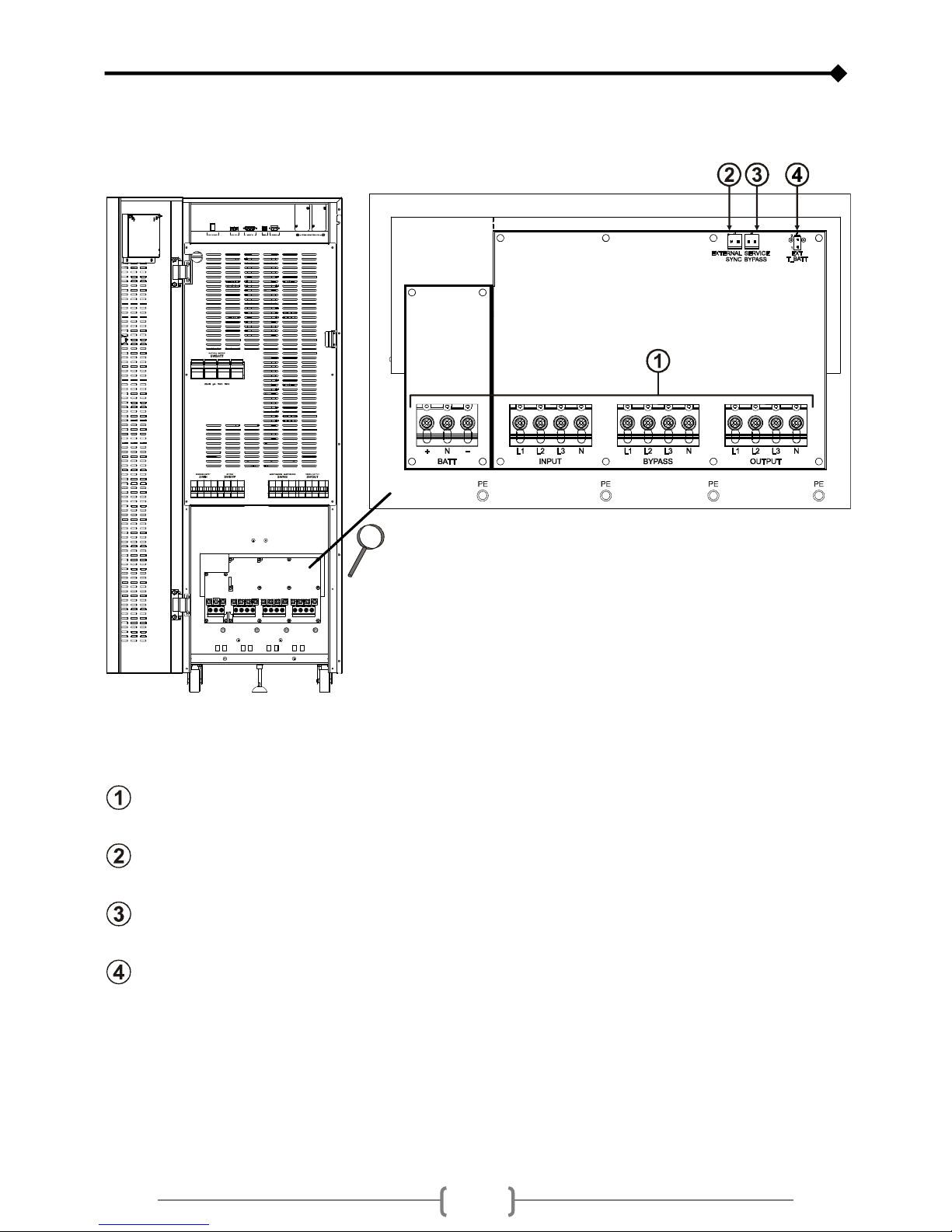
VIEWS OF THE UPS CONNECTIONS
Power connections: EXTERNAL BATTERY, INPUT, SEPARATE BYPASS (optional), OUTPUT
Connection for external synchronization signal
Connection for remote maintenance bypass command
Connection for external Battery Box temperature probe
58
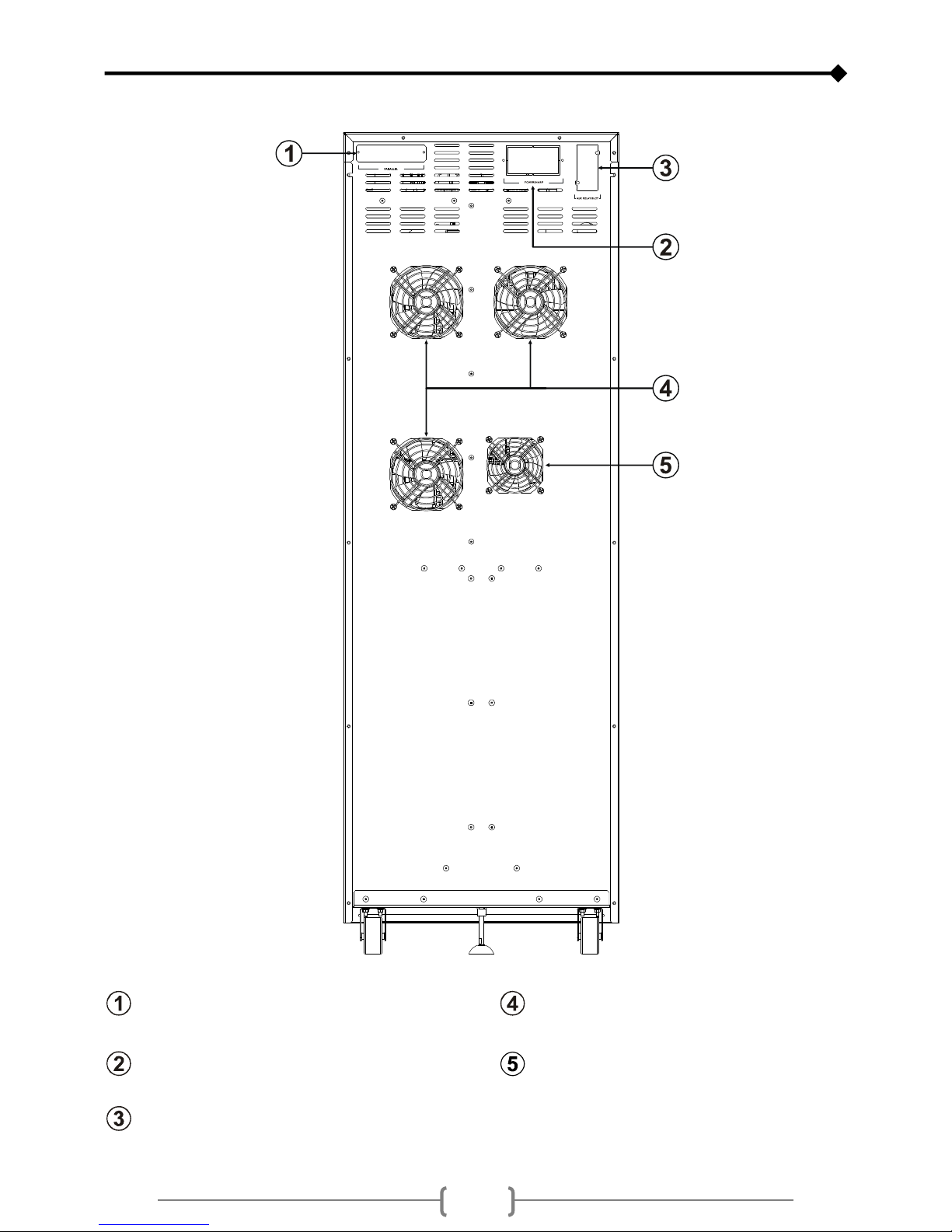
REAR VIEW OF THE UPS
Parallel board slot (optional)
Power board fans
Powershare socket / Power out socket Battery charger fan
Power relay board slot (optional)
59
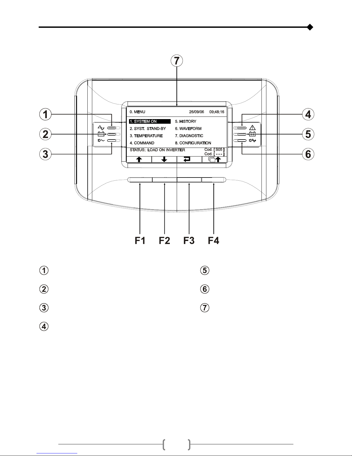
VIEW OF THE CONTROL PANEL
Mains power LED Low battery LED
Battery power LED ECO mode LED
Load on bypass LED Graphic display
Stand-by / alarm LED
F1, F2, F3, F4= FUNCTION KEYS. The function of each key is indicated at the bottom of the display and it varies
according to the menu.

60
SEPARATE BYPASS INPUT (OPTIONAL)
THE OPTIONAL DI VERSION OF THE UPS SERIES HAS SEPARATE BYPASS AND INPUT LINES.
The UPS series with Separate Bypass allows a separate connection between the input and the bypass lines.
The UPS output is synchronised with the bypass line, in order to avoid incorrect voltage changeovers during the alternate
phases, in case an automatic bypass or a maintenance isolator closure occurs.
61
INSTALLATION
ALL OPERATIONS DESCRIBED IN THIS SECTION MUST BE CARRIED OUT BY QUALIFIED PERSONNEL
ONLY.
The company assumes no responsibility for any damage caused by flawed connections or by operations
that are not described in this manual.
STORAGE OF THE UPS
The storage area must respect the following characteristics:
Temperature: 0°÷40°C (32°÷104°F)
Relative humidity degree: 95% max
PREPARATION FOR INSTALLATION
PRELIMINARY INFORMATION
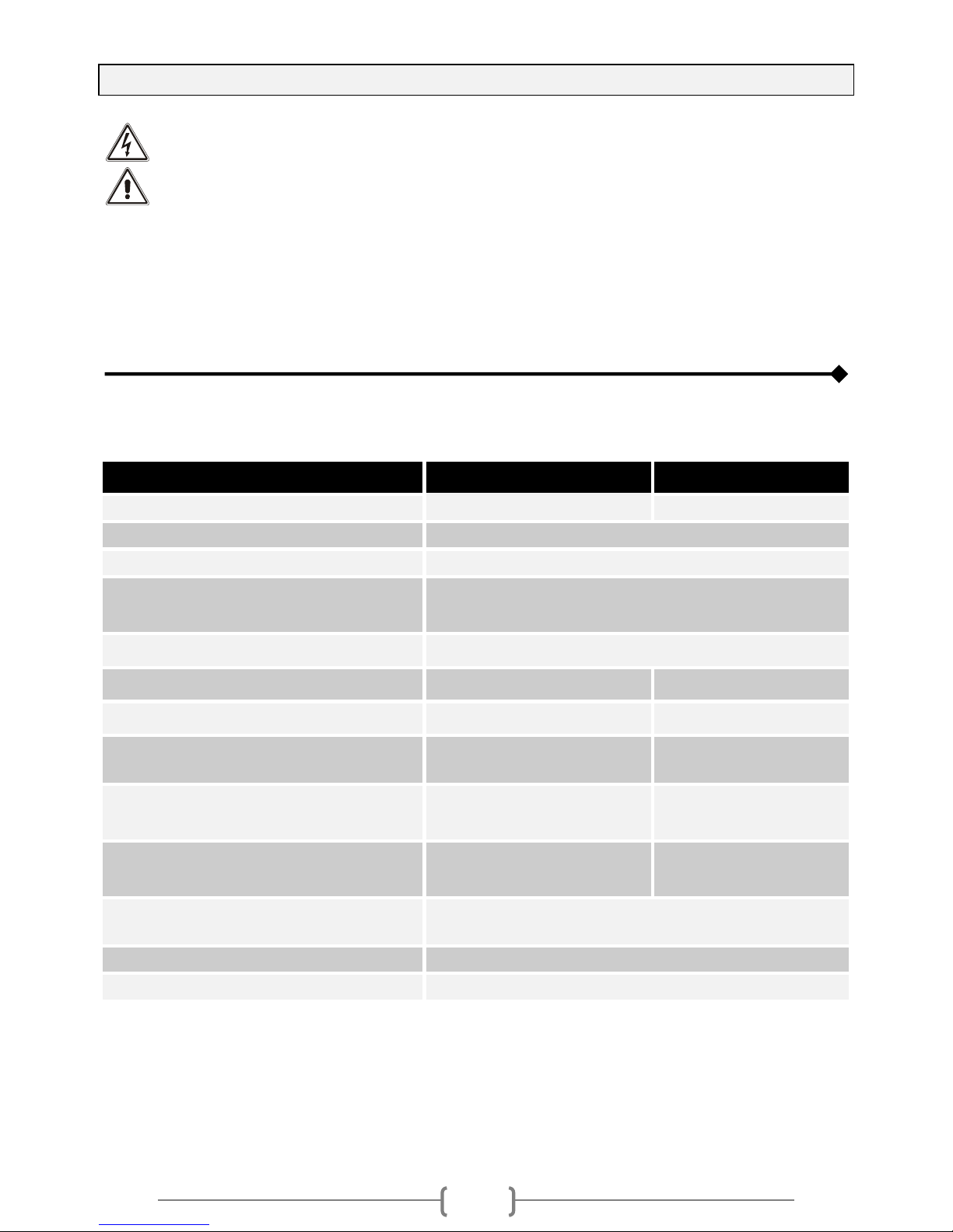
UPS Models 30 40
Nominal power 30kVA 40kVA
Operating temperature 0 ÷ 40 °C
Max. relative humidity during operation 90 % (no condensation)
Max. installation height 1000 m at nominal power rating
(-1% power for every 100 m over 1000 m)
max 4000 m
Dimensions W x D x H 440 x 850 X 1320 mm
Weight with no batteries 135kg 145kg
Weight with batteries 335kg 345kg
Dissipated power with nominal resistive load
(pf=0.9) and buffer battery (1)
1.4 kW
1205 kcal/h
4780 B.T.U./h
1.5 kW
1290 kcal/h
5120 B.T.U./h
Dissipated power with nominal distorting load
(pf=0.7) and charged battery (1)
1.34 kW
1150 kcal/h
4565 B.T.U./h
1.35 kW
1160 kcal/h
4605 B.T.U./h
Flow rate of the fans to remove heat from the
installation area (2) 750mc/h 800 mc/h
Current dispersion to earth (3) < 50 mA
Protection level IP20
Cable input On the rear from the bottom
(1) 3,97 B.T.U./h = 1 kcal/h
(2) The following formula can be used to calculate the air flow rate: Q [mc/h] = 3,1 x Pdiss [kcal/h] / (ta - te) [°C]
Pdiss is the power expressed in kcal/h dissipated by all the devices installed in the installation environment.
ta= ambient temperature, te=external temperature. In order to take leaks into account, it is necessary to increase
the value obtained by 10%.
The table shows an example of a flow rate with (ta - te) =5°C and a rated resistive load (pf=0.9).
(Note: This formula is applicable only if ta>te. If not, the UPS installation requires an air-conditioning system).
(3) The dispersion current of the load is added to that of the UPS on earth wire.

62
ELECTROMAGNETIC COMPATIBILITY
This UPS product conforms to the current electromagnetic compatibility (EMC) regulations (C2 class). It may cause radio
interference in the home environment. The user may have to adopt supplementary measures.
This product is for professional use in industrial and commercial environments. Connections to USB and RS232 connectors
must be made with the cables provided, or at least with shielded cables less than 3 metres long.
INSTALLATION ENVIRONMENT
As for the installation area of the UPS, and, if necessary, of the Battery Box, follow carefully the following instructions:
Avoid dusty environments
Make sure that the floor is level and that it is able to withstand the weight of the UPS (and of the Battery Box)
Avoid environments which are too narrow, as they could impede normal maintenance operations
The relative humidity should not exceed 90% with no condensation
Make sure that the ambient temperature remains between 0 and 40°C while the UPS is operating
This UPS can operate with an ambient temperature between 0 and 40°C. The recommended working
temperature for the UPS and the batteries is between 20 and 25°C. In fact, with a working temperature of
20°C, a battery has an average operating life of 5 years, whilst with a working temperature of 30°C the
operating life is halved.
Avoid positioning the UPS in places exposed to direct sunlight or hot air
To maintain the temperature in the installation area within the above mentioned range, there must be a system to dispose of the
dissipated heat (the kW / kcal/h / B.T.U./h values dissipated by the UPS are shown in the table in the previous page). The
methods that can be used are the following:
Natural ventilation
Forced ventilation, recommended when the external temperature is lower (e.g. 20°C) than the temperature at which the
UPS or the Battery Box has to be operated (e.g. 25°C)
Air-conditioning system, recommended when the external temperature is higher (e.g. 30°C) than the temperature at
which the UPS or the Battery Box has to be operated (e.g. 25°C)
63
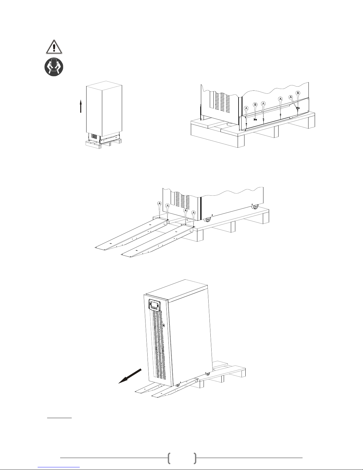
REMOVING THE UPS FROM THE PALLET
CAUTION! TO AVOID HARMING PEOPLE AND/OR DAMAGING THE EQUIPMENT, FOLLOW
CAREFULLY THE FOLLOWING INSTRUCTIONS.
SOME OF THESE INSTRUCTIONS NEED TO BE CARRIED OUT BY TWO PEOPLE.
Cut the straps and remove the cardboard box by
sliding it upwards. Remove the packaging material.
Remove the accessory box.
NOTE: the accessory box can be either inside the
packaging, or behind the USP door.
Remove the 2 brackets securing the UPS to the pallet by
unscrewing the screws marked A and B in the figure.
The previously removed brackets can also be used as slides. Secure the slides to the pallet by using the type A screws,
making sure they are aligned with the wheels.
Screw the brake rod completely, so to separate it from the pallet
Make sure that the door is firmly closed.
CAUTION! Push the UPS from the rear with great care. Given the weight of the equipment, this operation needs to
be carried out by two people.
NOTE : It is recommended to keep all parts of the packaging for further use

64
PRELIMINARY CHECK OF CONTENTS
Once the package has been opened, proceed to checking the contents:
metal slides, guarantee document, user manual, cd-rom containing the UPS management software, serial connecting cable, 4
battery fuses (to be inserted in the "SWBATT" fuse holders), door key.
POSITIONING THE UPS
When positioning the equipment, the following points should be taken into account:
The wheels are intended for accurate positioning, therefore for small movements only.
The plastic parts and the door are not suitable for pushing or gripping the UPS.
Sufficient space should be left in front of the equipment, for it to be switched on and off and in order to allow carrying
out maintenance operations on it ( ≥1,5 metres).
The rear part of the UPS should be placed at least at 30 cm from the wall, to allow the air blown by the ventilation fans
to outflow correctly.
No objects should be placed on its upper surface.
Once the equipment has been positioned, secure it with the apposite brake rod (see "Front views of the UPS ").
In earthquake-prone zones or in mobile systems it is possible to use the brackets securing the UPS to the pallet to anchor the
machine to the ground (see figure below). In normal conditions the brackets are not necessary.
OPERATIONS TO ACCESS THE TERMINALS OF THE UPS
To carry out the following operations, the UPS must be disconnected from the mains power supply,
switched off, and with all the equipment switches and fuse holders open.
Follow the instructions provided below to open the UPS:
Open the door using, if necessary, the key provided
Remove the terminal cover in correspondence with the switches (see "Front views of the UPS" )
Once the installation operations inside the equipment have been completed, replace the terminal cover and close the door.
65
ELECTRICAL CONNECTIONS
WARNING: a 4-wire three-phase distribution system is required.
The UPS must be connected to a power supply line made up of 3 phases + neutral + PE (protective earth) of TT, TN
or IT type. Therefore, the phase rotation must be respected.
Optional TRANSFORMER BOXES to convert the distribution systems from 3 wires to 4 wires are available.
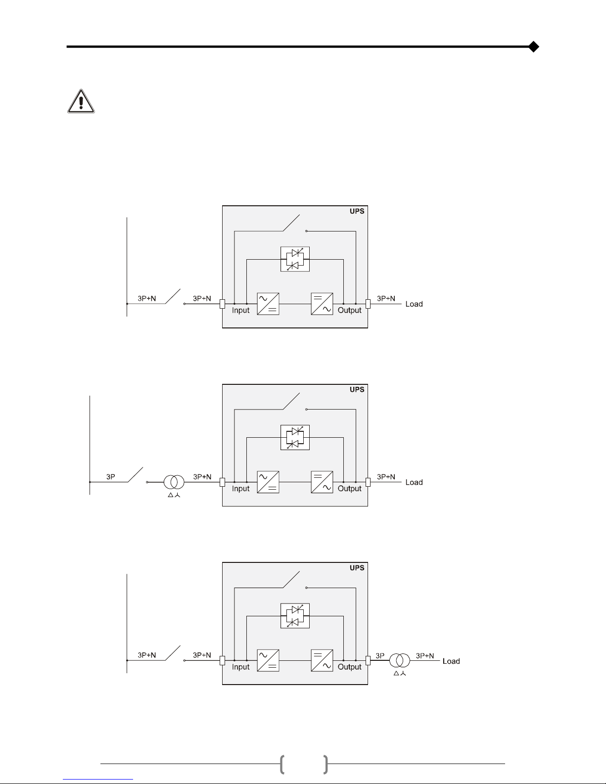
DIAGRAMS OF CONNECTIONS TO THE ELECTRICAL SYSTEM
UPS with no modification of the neutral regime
UPS with input galvanic isolation
UPS with output galvanic isolation

66
UPS with no modification of the neutral regime and with separate bypass input
UPS with input galvanic isolation and with separate bypass input
UPS with output galvanic isolation and separate bypass input

67
Separate bypass on separate lines:
When the separate bypass option is present, protective devices should be placed on both the main power supply line and the
bypass line.
Note: The neutral of the input line and that of the bypass are commoned inside the equipment, therefore they must refer to the
same potential. In case the two power supplies were different, an isolation transformer would be necessary on one of the
inputs.
UPS with no modification of the neutral regime and with separate bypass input
connected to an independent power supply line
UPS with separate bypass input connected to an independent power supply line
and with input galvanic isolation
UPS with separate bypass input connected to an independent power supply line
and with output galvanic isolation

68
UPS INTERNAL PROTECTIONS
The table below shows the sizes of the UPS isolators and the battery fuses (SWBATT) which are all accessible from the front of
the UPS. Moreover, the table shows the maximum input and the nominal output currents.
Fuses must be replaced with ones of the same type and of the same rating, as shown in the table.
Isolators and currents
UPS
Mod. Non-automatic switches Battery isolator Currents
[kVA] UPS input / Separate bypass UPS output / Maintenance Battery fuse
Input
current
[A]
Output
current
[A]
SWIN / SWBYP (optional) SWOUT / SWMB SWBATT Max *Nominal
30 63A(4P) 63A(4P) 80A gG 400V (22x58) 54A 46A
40 100A(4P) 100A(4P) 100A gG 400V (22x58) 70A 61A
*The maximum input current refers to a nominal load (PF = 0,9), to a 346V+ input voltage, and battery charger under a 7A
charge.
SHORT CIRCUIT
If a fault occurs on the load, the UPS protects itself by limiting the value and the duration of the current supplied (short circuit
current). These values also depend on the UPS operating status at the time of the fault, which can be either:
UPS in NORMAL OPERATION: the load is instantly commutated to the bypass line (UPS 30kVA I2t=20000A2s; UPS
40kVA I2t=25000A2s): the input line is connected to the output with no internal protection (locked after t>0.5s)
UPS in BATTERY OPERATION: the UPS protects itself by supplying an output current which is about 1.5 the nominal
current for 0.5s, after which it shuts down.
BACKFEED
This UPS is also equipped with an internal protection against backfeed through metal separation devices.
An optional output on the relay board is available for activating a release device to be installed upstream from the UPS.
This UPS has an internal device (redundant bypass power supply) which, in case a fault occurs, activates the bypass
automatically, thus maintaining the load powered with no internal protection and with no limit on the power supplied
to the load.
Under such emergency conditions, any disturbance on the input line will affect the load.
Please see the paragraph “Redundant auxiliary power supply for automatic bypass”, in the “USE” section.

69
EXTERNAL PROTECTION DEVICES
MAGNETOTHERMAL
In order to set up the power line, install a magnetothermal switch upstream from the UPS with intervention curve B or C. Please
follow the indications in the table below:
Automatic external protections
UPS Mod. Mains input Separate bypass input (optional)
30kVA 100A 100A
40kVA 100A 100A
If the protection device upstream of the UPS interrupts the neutral conductor, it must also interrupt all the phase
conductors at the same time (quadripolar switch).
Output protections (recommended selectivity values)
Normal fuses (gL-gG) In (Nominal current)/7
Magnetothermal switches (C curve) In (Nominal current)/7
Ultrarapid fuses (GF) In (Nominal current)/3
DIFFERENTIAL
In the absence of an input separating transformer, the neutral from the mains power supply is connected to the neutral of the
UPS output. This way the neutral regime of the equipment is not modified.
THE INPUT NEUTRAL IS CONNECTED TO THE OUTPUT NEUTRAL
THE DISTRIBUTION SYSTEM THAT POWERS THE UPS IS NOT MODIFIED BY THE UPS
WARNING: make sure that the equipment is connected correctly to the input neutral, or else
damages to the UPS may be caused.
The neutral regime is modified only in presence of an isolation transformer or when the UPS operates with a neutral
isolated upstream.
When operating from mains power, a differential switch located at the input can intervene as the output circuit is not isolated
from the input circuit. Anyhow, other differential switches can be inserted at the output, possibly coordinated with the switches at
the input.
The differential switch located upstream must have the following features:
Differential current adjusted to the sum of the UPS load. It is strongly recommended to keep an adequate margin in
order to avoid delayed interventions (100mA min. - 300mA recommended)
type B or type A
delay greater than or equal to 0,1s
This manual suits for next models
1
Table of contents


