ECOSTAR ECO 2 Installation guide

27.03.2020 Rev. 11
www.ecostar.com.tr
MONOBLOCK LIGHT OIL BURNERS INSTALLATION,
OPERATING AND MAINTENANCE MANUAL
ONE STAGE, TWO STAGE AND MODULATING OPERATION
ECO 1
ECO 2
ECO 30
ECO 45

27.03.2020 Rev. 11
1
DEAR USER,
ECOSTAR ECO 1, ECO 2, ECO 30, ECO 45 Light Oil burners are prepared and
manufactured according to the latest technical developments and safety rules. It is easy to
use for our customers.
We recommend that you read this manual and safety warnings thoroughly before the
use of the device in order to ensure safe, cost effective and environmental-friendly use.
If you encounter any issue that is not explained clearly in this manual or you could
not understand, please contact with our service department.
We thank you for choosing ECOSTAR brand.
Ecostar LIGHT OIL Burners are manufactured in accordance with TS EN 267
standards.
This Operating Manual is an integral part of the burner and must be maintained in a
plastic dossier and hung at a clearly visible place in the burner room.
TERMO ISI SİSTEMLERİ SAN.VE TİC.A.Ş.
Esentepe Mah.Milangaz Cad. No:75 K:3
Kartal Monumento Plaza
Kartal/İSTANBUL/TÜRKİYE
Tel: +90 216 442 93 00
Fax: +90 216 370 45 03
www.ecostar.com.tr
e-mail:[email protected]m.tr

27.03.2020 Rev. 11
2
CONTENTS
1. WARNINGS.......................................................................................................................................... 3
1.1. Warning Symbols and Descriptions............................................................................................... 3
1.2. General Safety Rules...................................................................................................................... 4
2. TERMS OF WARRANTY.................................................................................................................... 6
2.1. Out of Warranty Conditions.......................................................................................................... 6
3. BURNER’S GENERAL FEATURES................................................................................................... 7
3.1. Purpose of Use and Work Limits of Burners................................................................................. 7
3.2. Code Key........................................................................................................................................ 7
3.3. Burner Components........................................................................................................................ 9
4. FLUE GAS AND HEATING WATER SCHEMA............................................................................. 23
5. TECHNICAL DATA........................................................................................................................... 24
5.1. Capacity Table.............................................................................................................................. 24
5.2. Back Pressure-Capacity Diagrams............................................................................................... 25
5.3. Burner Dimensions....................................................................................................................... 27
5.4. Flame Length and Diameter......................................................................................................... 28
5.5. Noise Level................................................................................................................................... 28
6. BURNER HANDLING INFORMATION.......................................................................................... 28
7. INSTALLATION................................................................................................................................ 30
7.1. Burner Installation Picture............................................................................................................ 30
7.2. In reverse flame front mirror boilers............................................................................................ 31
7.3. In cylindrical (straight flame) boilers........................................................................................... 31
8. COMMISSIONING............................................................................................................................. 32
8.1. Before Commissioning................................................................................................................. 32
8.2. General Controls........................................................................................................................... 32
8.3. Combustion Adjustment............................................................................................................... 33
8.4. Fuel Pumps................................................................................................................................... 33
8.5. Servomotor Adjustment ............................................................................................................... 38
8.6. Emission Measurement ................................................................................................................ 38
8.7. Program Relay.............................................................................................................................. 39
8.8. Light Oil Burner Fuel Ring Line.................................................................................................. 41
9. MAINTENANCE................................................................................................................................ 42
9.1. Weekly Maintenance.................................................................................................................... 42
9.2. Monthly Maintenance................................................................................................................... 42
9.3. Seasonal Maintenance.................................................................................................................. 43
9.4. Installation and Disassembly Instructions for Maintenance Purposes......................................... 44
10. TROUBLESHOOTING................................................................................................................... 45
11. PERIODICAL FLUE GAS MEASUREMENT REPORT.............................................................. 46
12. AFTER-SALES SERVICES............................................................................................................ 47
13. NOTES............................................................................................................................................. 48

27.03.2020 Rev. 11
3
1. WARNINGS
1.1. Warning Symbols and Descriptions
Symbols
Symbol Descriptions
Important information and useful hints.
Warning of danger to life or property.
Warning of electrical voltage.
Product handling information.
Electric motor direction of rotation
Carry in an upright position. Fragile Item. Protect against water.

27.03.2020 Rev. 11
4
1.2. General Safety Rules
All personnel engaged in installation, disassembly, commissioning, operation, control,
maintenance and repair should have received the necessary training and fully read and understood
this manual.
No changes that might damage the safety of the burner unit must be made by persons and/or
organizations on the burner unit.
All operation, commissioning and installation works (except for burning adjustment) should be
carried out when the burner is not operating and after disconnecting the power supply.
Noncompliance with these rules may lead to serious bodily injuries and even death by electrical
shocks or uncontrolled flame formation.
Repairs concerned with safety elements should be carried out only by the manufacturing company.
The device should never be used by children, mentally handicapped and inexperienced persons.
Children must not be allowed to play with the device.
Keep the device away from explosive and flammable materials.
Device must intake air, ventilation and air discharge holes must not be closed.
Do not store any inflammable materials in boiler room.
Wear hearing protectors if there is noise in boiler room.
In case of fıre or other emergency;
●Switch off the main switch
●Take appropriate actions
27.03.2020 Rev. 11
5
The burner installation must be carried out in accordance with the instructions. Vibration can
damage the burner and its components.
Keep boiler doors closed while starting burner and during burner operation.
Check combustion values to be correct by using flue gas analyzer at the whole adjustment range
between minimum, full load, and ignition load.
Use lifting device or belt for lifting fan motor, if necessary.
During the first commissioning of the burner or in case of any revision carried out in the electrical
system or motor cables by any reason, direction of the fan rotation must certainly be checked by
the authorized technical service.
For products that have not been comissioned or started more than 6 months, before activating the
servomotor;
In air dampers and oil regulators, servomotor and air damper connections must be checked to
ensure that they are free running in spite of immobility and oil freezing.
BURNER ROOM
Install the burner in a suitable room/floor with minimum external air openings and sufficient to
ensu re perfect combustion, in compliance with current regulations.
Never obstruct air openings of the burner room, burner fan intake vents or air ducts in order to
prevent:
a.The build up of toxic / explosive gas mixtures in the burner room,
b.Combustion with insufficient air, resulting in hazardous, anti-economical and polluting ope-
ration.
The burner must be always protected from rain, snow and frost to prevent corrosion and paint
deformations.
Keep the burner room clean and free of solid volatile substances, which could be sucked into the fan
and clog the internal burner or combustion head air ducts.

27.03.2020 Rev. 11
6
2. TERMS OF WARRANTY
Main and auxiliary equipment and all components used in Ecostar light oil burners are guaranteed
for 1 year by TERMO ISI SİST. A.Ş starting from the date of commissioning under the maintenance,
adjustment, operating conditions and relevant mechanic, chemical and thermal effects explained herein.
Please note that this warranty is only valid if the device(s) is commissioned and maintained by our
authorized services.
Our company reserves the right to make any modifications on the product and all instructions
thereof for improvement purposes.
2.1. Out of Warranty Conditions
Any damage arising out of or in relation to customers’ non-compliance to their responsibilities
with regards to installation, commissioning, operation and maintenance,
Any damage arising out of or in relation to commissioning, repairs and maintenance carried out by
unauthorized services,
Any damage that may occur during transportation or storage of the product,
Not preserving the product in its original packaging until the installation stage,
Incorrect and poor electrical connections, Failures due to incorrect voltage applications, frequent
repetition of voltage fluctuations,
Any damage that may occur as a result of incorrect fuel usage or, foreign substances in the fuel
used or using of the product without any fuel,
Any damage that may occur due to foreign particles entered into the product during installation
and operation,
Failures due to incorrect device selection,
Any damage to unit due to natural disasters,
Devices without any warranty certificates,
Warranty Certificates without the stamp and signature of the authorized dealer or service,
Devices with any falsification on the warranty certificate or without an original serial number.
The risks during transportation of device under the responsibility of customer belong to the
customer.
Presence of misuse faults are indicated in the reports issued by authorized service stations or our
authorized agent, dealer, representative or our factory in case of unavailability of authorized
service stations.
Customers may apply consumer protection arbitrator committee with regards to this report and
request for an expert report.

27.03.2020 Rev. 11
7
3. BURNER’S GENERAL FEATURES
ECOSTAR light oil burners are designed to operate with oil at 2.5 –6 Cst (mm²/s) viscosity, at
rated capacity and pressure ranges and -15% to +10% nominal voltage.
3.1. Purpose of Use and Work Limits of Burners
This product works at any load value equivalent to its max. capacity or covered by its capacity
range;
-In hot water and steam boilers,
-In direct and indirect hot air generators,
-Industrial appliances operating at temperature below 600 0C,
--15 0C…+60 0C ambient temperature range,
-1N 230 VAC/3N 380VAC /50 Hz feed voltage (-%15…+%10) values,
-Max. 95% relative humidity,
-In well-ventilated open and closed spaces compatible with protection class IP 40.
This device must never be operated with open flame!
3.2. Code Key

27.03.2020 Rev. 11
8
Temperature change of fuel used in ECOSTAR light oil burners dependent on viscosity
27.03.2020 Rev. 11
9
3.3. Burner Components
ECO 1 OLC1-1a

27.03.2020 Rev. 11
10
Assembly No
Part Name
Assembly No
Part Name
1
Body
12
Gasket
2
Flame Tube
13
Lance Mechanism
3
Transformer Mounting Plate
14
Air Adjustment Mechanism
4
Ignition Transformer
15
Air Damper
5
Control Relay
16
Air Damper Gauge
6
Ignition Electrode
17
Photocell
7
Fan
18
Observation Glass
8
Motor
19
Lance Cover
9
Pump
20
Lance Plate
10
Combustion Head
21
Fuel Pipe
11
Boiler Connection Flange
22
Fuel Nozzle

27.03.2020 Rev. 11
11
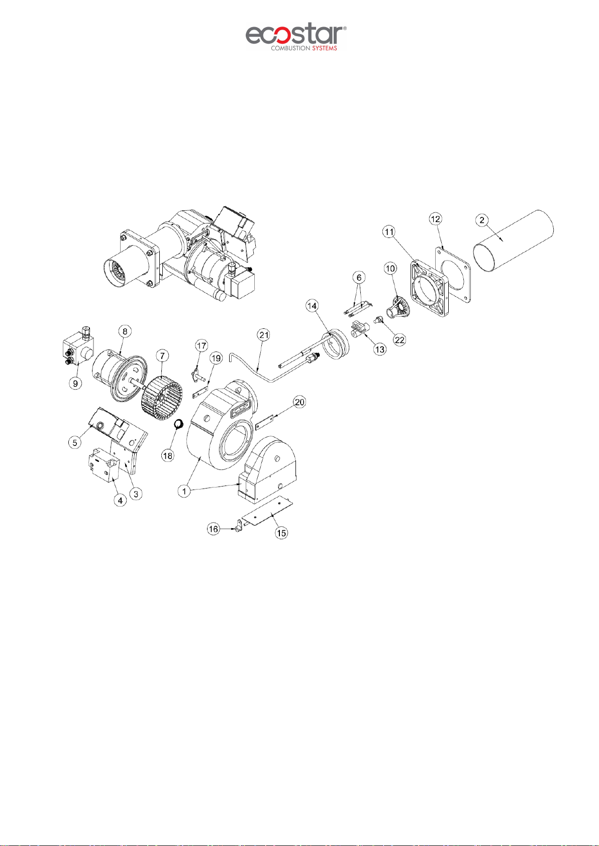
ECO 2 OLC1-1a

27.03.2020 Rev. 11
12
Assembly No
Part Name
Assembly No
Part Name
1
Body
15
Handling Shaft
2
Flame Tube
16
Observation Glass
3
Flame Tube Extension
17
Air Damper Gauge
4
Boiler Connection Flange
18
Air Damper
5
Gasket
19
Coupling Connection Pipe
6
Klingerit Gasket
20
Pump Coupling
7
Fan
21
Fan Coupling
8
Motor
22
Pump
9
Ignition Transformer
23
Lance
10
Photocell
24
Ignition Electrode
11
Transformer Mounting Plate
25
Electrode Connection Sheet Metal
12
Purger
26
Combustion Head
13
Electrical Panel
27
Fuel Pipe
14
Electrical Panel Mounting Plate
28
Fuel Nozzle
27.03.2020 Rev. 11
13
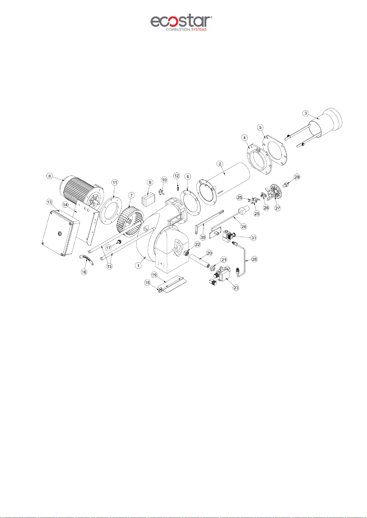
ECO 30 OLC1-1a

27.03.2020 Rev. 11
14
Assembly No
Part Name
Assembly No
Part Name
1
Body
17
Observation Glass
2
Flame Tube
18
Damper Gauge
3
Flame Tube Extension
19
Air Damper
4
Boiler Connection Flange
20
Coupling Connection Pipe
5
Gasket
21
Pump Coupling
6
Klingerit Gasket
22
Fan Coupling
7
Fan
23
Pump
8
Motor
24
Lance
9
Ignition Transformer
25
Ignition Electrode
10
Photocell
26
Electrode Connection Sheet Metal
11
Fan Motor Connection Flange
27
Combustion Head
12
Purger
28
Fuel Pipe
13
Electrical Panel
29
Fuel Nozzle
14
Electrical Panel Mounting Plate
30
Lance Centring Console
15
Handling Shaft
31
Solenoid Valve
16
Shaft Fixing Plate
27.03.2020 Rev. 11
15
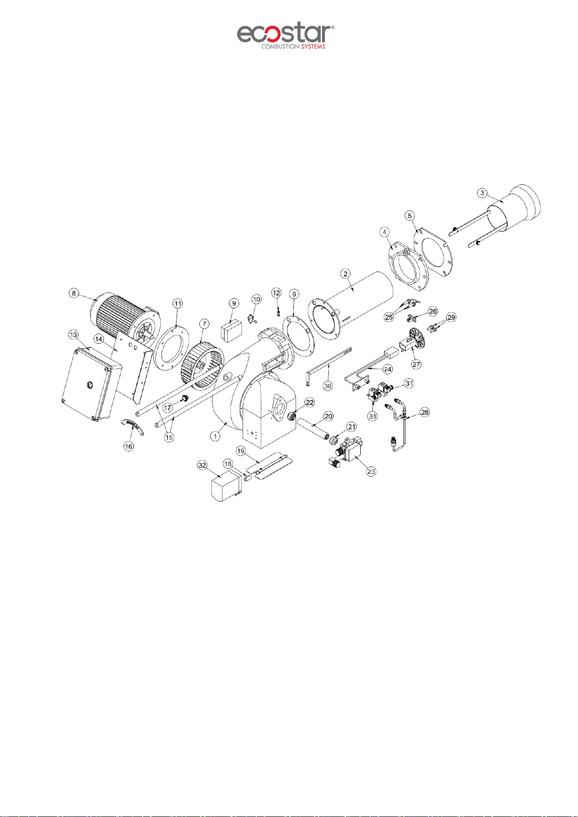
ECO 30 OLC2-2a

27.03.2020 Rev. 11
16
Assembly No
Part Name
Assembly No
Part Name
1
Body
17
Observation Glass
2
Flame Tube
18
Damper Gauge
3
Flame Tube Extension
19
Air Damper
4
Boiler Connection Flange
20
Coupling Connection Pipe
5
Gasket
21
Pump Coupling
6
Klingerit Gasket
22
Fan Coupling
7
Fan
23
Pump
8
Motor
24
Lance
9
Ignition Transformer
25
Ignition Electrode
10
Photocell
26
Electrode Connection Sheet Metal
11
Fan Motor Connection Flange
27
Combustion Head
12
Purger
28
Fuel Pipe
13
Electrical Panel
29
Fuel Nozzle
14
Electrical Panel Mounting Plate
30
Lance Centring Console
15
Handling Shaft
31
Solenoid Valve
16
Shaft Fixing Plate
32
Servomotor

27.03.2020 Rev. 11
17
ECO 45 OLC1-1a-1b

27.03.2020 Rev. 11
18
Assembly No
Part Name
Assembly No
Part Name
1
Body
18
Air Damper
2
Klingerit Gasket
19
Air Damper
3
Flame Tube
20
Air Damper Motion Rod
4
Flame Tube Extension
21
Air Damper Motion Transfer Rod
5
Gasket
22
Fan Coupling
6
Boiler Connection Flange
23
Coupling Connection Pipe
7
Fan
24
Pump Coupling
8
Motor
25
Pump
9
Electrical Panel
26
Fuel Pipe
10
Electrical Panel Mounting Plate
27
Solenoid Valve
11
Handling Shaft
28
Lance
12
Shaft Fixing Plate
29
Lance Centring Console
13
Observation Glass
30
Ignition Electrode
14
Ignition Transformer
31
Electrode Connection Sheet Metal
15
Photocell
32
Combustion Head
16
Purger
33
Fuel Nozzle
17
Damper Gauge

27.03.2020 Rev. 11
19
ECO 45 OLC2-2a-2b
This manual suits for next models
3
Table of contents
Other ECOSTAR Industrial Equipment manuals


Popular Industrial Equipment manuals by other brands

Afag
Afag SE-Power FS Operating instruction

Dover
Dover Liquip Swift Driver manual

Rodix
Rodix FC-40 Plus Series Adjustments and Set Up

Siemens
Siemens 3VL9400-3M.00 manual

SUHNER
SUHNER WI 7 Technical document

Rockwell Automation
Rockwell Automation Allen-Bradley ControlNet Ex Media Planning and installation manual


