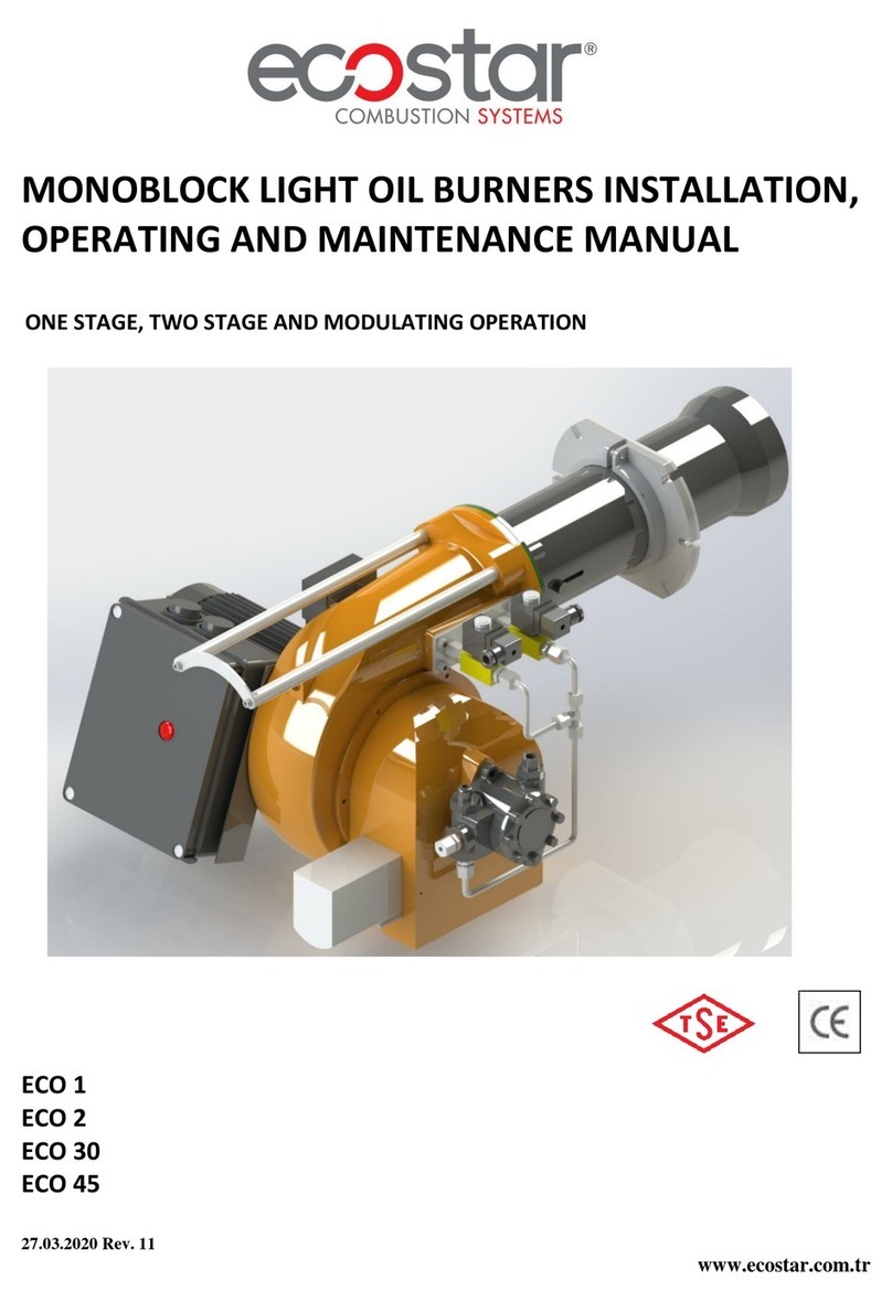
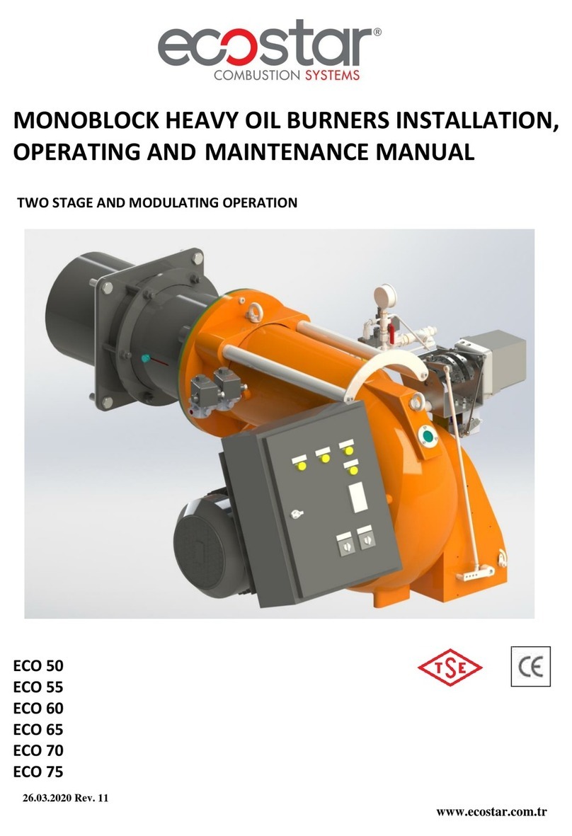
ECOSTAR ECO 1.0 Installation guide

19.10.2018 Rev. 07 1
DEAR USER,
ECOSTAR ECO1.0,ECO2.0,ECO30.0Square BodyLightOil burnersare
prepared and manufacturedaccordingtothe latest technical developments and safetyrules.
It is easyto use for ourcustomers.
We recommendthat you readthis manual andsafety warningsthoroughlybeforethe
useof the deviceinordertoensure safe, cost effective andenvironmental-friendly use.
Ifyou encounterany issuethat isnotexplainedclearly inthismanual or youcould
not understand,please contact withour service department.
We thank youforchoosingECOSTAR brand.
EcostarLight Oil Burners aremanufacturedinaccordance withTS EN 267 standards.
This OperatingManualisanintegralpartof theburnerand must bemaintainedin a
plasticdossierand hungat a clearlyvisible placeinthe burnerroom.
TERMO ISI S STEMLER SAN.VET C.A.Ş.
EsentepeMah.MilangazCad. No:75 K:3
KartalMonumentoPlaza
Kartal/ STANBUL/TÜRK YE
Tel: +90 216 442 93 00
Fax:+90 216 370 45 03
www.ecostar.com.tr
e-mail:servis@ecostar.com.tr

19.10.2018 Rev. 07 2
CONTENTS
1. WARNINGS .......................................................................................................................................3
1.1. Warning Symbolsand Descriptions .............................................................................................3
1.2. General Safety Rules....................................................................................................................4
2. TERMS OFWARRANTY..................................................................................................................6
2.1. Out ofWarranty Conditions........................................................................................................6
3. BURNER’SGENERALFEATURES.................................................................................................7
3.1. Purposeof Use and Work Limits ofBurners................................................................................7
3.2. Code Key......................................................................................................................................7
3.3. Burner Components......................................................................................................................9
4. TECHNICAL DATA ........................................................................................................................11
4.1. Capacity Table...........................................................................................................................11
4.2. BackPressure-Capacity Diagrams.............................................................................................12
4.3. Burner Dimensions.....................................................................................................................15
4.4. FlameLength andDiameter.......................................................................................................15
4.5. NoiseLevel ................................................................................................................................15
5. BURNER HANDLING INFORMATION ........................................................................................16
6. INSTALLATION..............................................................................................................................17
6.1. Burner InstallationPicture..........................................................................................................17
6.2. Inreverse flamefrontmirror boilers..........................................................................................18
6.3. Incylindrical (straight flame) boilers.........................................................................................18
7. COMMISSIONING..........................................................................................................................19
7.1. Before Commissioning...............................................................................................................19
7.2. General Controls........................................................................................................................19
7.3. Combustion Adjustment.............................................................................................................20
7.4. Fuel Pumps.................................................................................................................................20
7.5. Servomotor Adjustment.............................................................................................................22
7.6. EmissionMeasurement ..............................................................................................................22
7.7. ProgramRelay............................................................................................................................23
7.8. LightOilBurner FuelRingLine................................................................................................24
8. MAINTENANCE..............................................................................................................................25
8.1. Weekly Maintenance..................................................................................................................25
8.2. MonthlyMaintenance.................................................................................................................25
8.3. Seasonal Maintenance................................................................................................................26
8.4. Installationand Disassembly Instructionsfor MaintenancePurposes........................................27
9. TROUBLESHOOTING....................................................................................................................29
10. PERIODICAL FLUEGASMEASUREMENTREPORT.............................................................30
11. AFTERSALES SERVICES..........................................................................................................31
12. NOTES..........................................................................................................................................32

19.10.2018 Rev. 07 3
1. WARNINGS
1.1. WarningSymbolsandDescriptions
Symbols SymbolDescriptions
Important information and usefulhints.
Warning of danger to lifeor property.
Warningofelectrical voltage.
Product handling information.
Flametube adjustment
1stand 2nd Stageselection switch
Carry inanupright position.Fragile Item.Protectagainstwater.

19.10.2018 Rev. 07 4
1.2. General Safety Rules
•All personnel engagedininstallation,disassembly,commissioning,operation,control,
maintenanceand repair should havereceived thenecessarytrainingandfullyreadand understood
thismanual.
•Nochangesthatmightdamage thesafety oftheburnerunit must be madeby persons and/or
organizations onthe burnerunit.
•All operation,commissioning and installation works (except for burningadjustment) should be
carried out when theburnerisnotoperating and afterdisconnecting the power supply.
Noncompliancewith theserules may lead to seriousbodilyinjuriesand even death by electrical
shocksoruncontrolled flameformation.
•Repairs concerned withsafety elementsshould becarriedout only bythemanufacturingcompany.
•The deviceshouldnever be usedbychildren,mentally handicapped and inexperienced persons.
•Children mustnot be allowed to playwith the device.
•Keep the deviceaway fromexplosiveand flammable materials.
•Devicemustintakeair,ventilation andair discharge holesmust not beclosed.
Do not store any inflammablematerialsinboiler room.
Wear hearingprotectorsifthereisnoiseinboiler room.
Incaseoffıreorother emergency;
Switchoff the mainswitch
Takeappropriate actions
Installburner firmly.Vibrationmaydamageburner oritscomponents.
Keep boiler doorsclosedwhilestartingburner and duringburner operation.

19.10.2018 Rev. 07 5
Check combustionvalues tobe correct byusingflue gasanalysis atthewhole adjustment range
between minimum,fullload, and ignitionload.
Use liftingdeviceorbelt for liftingfanmotor,ifnecessary.
During thefirstcommissioning oftheburner orincase of any revision carried out inthe electrical
systemor motor cables byanyreason,directionofthefan rotation mustcertainly be checkedby
the authorizedtechnical service.
For products thathavenotbeencomissioned or startedmorethan 6months,before activating the
servomotor;
In air dampersandoil regulators, servomotor andair damper connectionsmustbechecked to
ensure that they arefreerunning inspiteofimmobilityand oilfreezing.
BURNER ROOM
Installthe burner inasuitable room/floor withminimumexternalairopenings and sufficient to
ensu reperfect combustion,incompliancewith current regulations.
Never obstruct airopenings oftheburner room,burner fan intake vents or airducts inorder to
prevent:
a.Thebuildupoftoxic /explosive gas mixtures inthe burner room,
b.Combustionwith insufficient air, resultingin hazardous, anti-economical and polluting ope-
ration.
Theburner mustbealways protectedfromrain,snowand frosttoprevent corrosionand paint
deformations.
Keeptheburner roomclean and freeofsolidvolatile substances,which could besuckedintothefan
and clog theinternalburnerorcombustion head airducts.

19.10.2018 Rev. 07 6
2. TERMS OFWARRANTY
Main and auxiliary equipmentand all componentsused in Ecostar light oil burners are guaranteed
for 1yearby TERMOISISIST.A.Şstarting fromthedate of commissioning under themaintenance,
adjustment, operatingconditionsand relevant mechanic,chemical and thermal effectsexplainedherein.
Pleasenote that thiswarranty isonlyvalidifthedevice(s)is commissioned and maintained by our
authorizedservices.
Our company reserves the right to makeanymodificationson the product and all instructions
thereof for improvement purposes.
2.1. OutofWarranty Conditions
•Any damage arising out oforin relation to customers’non-complianceto their responsibilities
with regardstoinstallation, commissioning,operation andmaintenance,
•Any damage arising out ofor inrelation to commissioning,repairsand maintenancecarried out by
unauthorized services,
•Any damage thatmayoccur during transportationorstorageofthe product,
•Not preserving the productinits original packaginguntiltheinstallationstage,
•Incorrectand poorelectrical connections,Failuresdue toincorrect voltage applications,frequent
repetition ofvoltage fluctuations,
•Any damagethat may occur as aresultofincorrect fuel usage or,foreign substancesinthe fuel
used or using ofthe productwithoutanyfuel,
•Any damage that mayoccur dueto foreignparticles entered into theproduct during installation
andoperation,
•Failuresdue toincorrectdeviceselection,
•Any damage tounitduetonatural disasters,
•Deviceswithoutany warranty certificates,
•Warranty Certificateswithoutthe stampand signature oftheauthorizeddealer or service,
•Devices with anyfalsificationonthewarranty certificate or without an originalserial number.
•The risks during transportation ofdevice undertheresponsibilityof customerbelong to the
customer.
•Presenceofmisuse faults areindicated in the reportsissued by authorized servicestations or our
authorizedagent,dealer,representative orour factory in case ofunavailability ofauthorized
service stations.
•Customers may apply consumer protectionarbitrator committeewith regardsto thisreport and
requestfor anexpert report.

19.10.2018 Rev. 07 7
3. BURNER’SGENERAL FEATURES
ECOSTARlight oilburnersare designed tooperate with oil at 2.5–6Cst (mm²/s)viscosity,at
rated capacity andpressure ranges and-15% to+10% nominalvoltage.
3.1. Purpose ofUseand WorkLimitsof Burners
•Thisproduct works at any load value equivalentto itsmax.capacity or covered by itscapacity
range;
-In hotwater andsteamboilers,
-In directand indirecthot airgenerators,
-Industrialappliancesoperatingattemperature below 600 0C,
--15 0C…+60 0Cambient temperature range,
-1N230VAC/3N 380VAC/50Hz feed voltage(-%15…+%10) values,
-Max.95%relative humidity,
-In well-ventilatedopenandclosed spaces compatible withprotection class IP40.
This devicemust never beoperatedwithopenflame!
3.2. CodeKey

19.10.2018 Rev. 07 8
Temperature change of fuel usedinECOSTAR light oilburnersdependent onviscosity

19.10.2018 Rev. 07 9
3.3. Burner Components
ECO 1.0
AssemblyNo
PartName AssemblyNo
PartName
1 Housingcover 10 Air klappe
2 Relay 11 Air klappe adjustingscrew
3 Fuel pump 12 Cover
4
Pump
-
lance connecting
group 13 Body
5 Ignition transformer 14 Filter
6 Motor 15 Lance
7 Installation sheet 16 Flametube
8 Fan 17 Boiler connection flange
9 Electricconnection socket 18 Diffuser

19.10.2018 Rev. 07 10
ECO 2.0-ECO 30.0
AssemblyNo
PartName AssemblyNo
PartName
1 Housingcover 11 Fan
2 Relay 12 Air klappe
3 Fuel pump 13 Air klappe driveshaft
4 Ignition transformer 14 Electricinstallation sheet
5 Servomotor 15 Spiral casing
6 Motor 16 Electricconnectionsocket
7 Bulls eye 17 Flametube
8 Servicecover 18 Boiler connection flange
9 Lance 19 Flametube extension
10 Installation sheet 20 Diffuser

19.10.2018 Rev. 07 11
4. TECHNICAL DATA
4.1. CapacityTable
SQUAREBODY MONOBLOCK LIGHTOIL BURNERSCAPACITY TABLE
BURNER TYPE CAPACITY CAPACITY LIGHT OIL
CONSUMPTION
FAN
MOTOR
POWER MAIN SUPPLY
Min.
Kcal/h Max.
Kcal/h Min.kW Max. kW Min.
Kg/h Max. Kg/h kW VAC
ONESTAGE LIGHT OIL BURNERS
ECO1.0OLC 1 10.200 35.700 12 42 1,0 3,5 0,15 1N230
ECO1.0OLC 1a 15.300 51.000 18 59 1,5 5,0 0,15 1N230
ECO1.0OLC 1b 20.400 71.400 24 83 2,0 7,0 0,15 1N230
ECO1.0OLC 1 c 25.500 84.660 30 98 2,5 8,3 0,15 1N230
ECO2.0OLC 1 59.976 132.600 70 154 5,9 13,0 0,15 1N230
ECO2.0OLC 1a 71.400 173.400 83 202 7,0 17,0 0,15 1N230
ECO2.0OLC 1b 81.600 214.200 95 249 8,0 21,0 0,25 1N230
ECO2.0OLC 1c 107.100 265.200 125 308 10,5 26,0 0,25 1N230
TWO STAGE LIGHT OILBURNERS
ECO2.0OLC 2 59.976 132.600 70 154 5,9 13,0 0,15 1N230
ECO2.0OLC 2a 71.400 173.400 83 202 7,0 17,0 0,15 1N230
ECO2.0OLC 2b 81.600 214.200 95 249 8,0 21,0 0,25 1N230
ECO2.0OLC 2c 107.100 265.200 125 308 10,5 26,0 0,25 1N230
ECO30.0OL C 2 112.200 306.000 130 356 11 30 0,25 1N230
ECO30.0OL C 2a 132.600 387.600 154 451 13 38 0,55 1N230
ECO30.0OL C 2b 142.800 469.200 166 546 14 46 0,55 1N230
ECO30.0OL C 2c 163.200 530.400 190 617 16 52 0,55 1N230
Hu Light Oil(L)=10200 Kcal/kg

19.10.2018 Rev. 07 12
4.2. BackPressure-Capacity Diagrams

19.10.2018 Rev. 07 13

19.10.2018 Rev. 07 14

19.10.2018 Rev. 07 15
4.3. Burner Dimensions
4.4. Flame Lengthand Diameter
4.5. Noise Level
Product operateswithinthe range of 70decibelsmax.and74 decibels.

19.10.2018 Rev. 07 16
5. BURNER HANDLINGINFORMATION
•Lifttheproduct byholdingthehandlesasseeninthe picture.
•Prevent strong impactsontopoftheproductandvibrationwhile handling theproduct.
•Donotleavetheproductinwet environment.
Dimensions ofthebox used for handling
Burner LxW x H (cm) Weight(kg)
ECO1.0 70X 33 X35 24
ECO2.0
65 X36X47
36
ECO30.0
75
X43X54
36

19.10.2018 Rev. 07 17
6. INSTALLATION
6.1. Burner Installation Picture
1- DriftBolts
2- BurnerBody
3- BoilerConnection Flange
4- Gasket
5- BoilerStuds
ØIn theinstallation oftheburner,use theinstallationmaterials suppliedwith the burner.
ØSecuretheburnerconnection flange ontothe burner cover by 4bolts.Gasket mustbe connected
such that it willremain betweenconnectingflange and boiler cap.
Aftercompletingthe installationof the burneron theboiler:
ØConnect the oil feedpipes.
ØConnect the burnerpaneltothemainsbyacable suitable for theratedpower.
Clean the insideof fuelline thoroughly beforeinstalling theburnertothe fuel line.Any damage
that may occur dueto solidobjects andmetal particles fromthe fuelline shall notbe coveredby
our company.

19.10.2018 Rev. 07 18
6.2. Inreverse flamefrontmirror boilers
While installing theburner in reverse flamefront
mirror boilers,flametubetipmustbeadjusted such
that itgetsinside by 50 mm-100 mmfromfluepipes
(50mm≤A≤100mm).Otherwiseflue gastemperature will
riseandfuel consumption will increase.
6.3. Incylindrical (straightflame)boilers

19.10.2018 Rev. 07 19
7. COMMISSIONING
7.1. BeforeCommissioning
Electricalconnection
Performelectricalconnections according to thediagramprovided withthe burner.Followgeneral
securityrules duringinstallationofelectric wiringand making connections. Connect the earthingterminal
in electric panel tothe earthing installation.
7.2. General Controls
Make suretoperformthe following controlsbeforecommissioningtheburner.
ØInstallationoftheburner totheboileris checked.
ØCheckthe fuel line(are the pipediametersand thepipe installation correct?).
ØCheckenergy input cablesand voltages.
ØCheckthe boiler safetythermostats and,if it isatwo-stage burner,then makesure thatthere are
twothermostats.
ØCheckthe fuel nozzles according totheboiler capacity.
ØPriortooperating the burner, controlthe boilerwater level.
ØMakesure water circulation systemisturnedon,and steamboiler andwaterfeedpumps and
boilerinlet -outletsareopen.
Commissioningorder
ØAfter performingtheabovementioned controls,open the fuel tankvalve.
ØOpenthevalve upstreamofthe fuel filter.
ØCheck direction ofmotor rotation.
ØOpenthepump’s vent plugand placethe manometer (0-40bar).
ØTurn ontheburner switch (turn toposition 1).
ØWhen theburner startsup,themotor isactivated and turns thepumpatthe sametime.
ØIt actuatespre-purgeanddischarges theresidual gases remaining intheboiler fromthe funnel.
ØAfter thepre-purge,fuel is deliveredfromthe nozzle.The fuelmeetstheflamefromtheignition
electrodesandthe combustionstarts.
ØAfter combustionoftheburner,thepumppressure isadjusted (lightoil:14 bar).
ØIfthe burner has twostages,theswitch is brought to position “2”,and the capacity of theburner is
increasedthrough servomotor.Ideal combustion is obtained by increasing the amount ofairby the
fuel given accordingtoanalyses value.
ØThe boiler thermostat is adjustedasdesired(70-90°Cfor central heating boilers).
ØFor the safety of thesystem,check the boilerthermostats and observe the deactivation ofthe
burner.
Other manuals for ECO 1.0
1
This manual suits for next models
18
Table of contents
Other ECOSTAR Industrial Equipment manuals
Popular Industrial Equipment manuals by other brands

Spirax Sarco
Spirax Sarco UTD26 Series Installation and maintenance instructions

ABB
ABB HT613215 Operation manual

Graco
Graco SaniForce SDU Series manual

Alpha
Alpha Pre-Plumb 20 Installation and servicing instruction

riverhawk
riverhawk IM-164 instruction manual

SCHUNK
SCHUNK OSE 40 Assembly and operating manual