ECOVOLVE ED1000 Service manual
ED1000 BATTERY HI-TIP DUMPER
OPERATOR’S HANDBOOK

THIS OPERATOR’S HANDBOOK contains information for operating the ED1000.
This operator’s hand book must be stored in the manual holder on the machine.
A full and comprehensive instruction guide can also be found in the OWNERS
MANUAL which is supplied with the truck. The OWNERS MANUAL can also be found
in the downloads section on the ecovolve website, www.ecovolve.eu.
The OWNERS MANUAL contains more detailed and complete information on the
operation, maintenance, transport, servicing and technical data for the ED1000.
Manufacturer : Ecovolve
Model : ED1000
Serial number : ....................................
Date: .............................................

Contents
5.
7.
6.
4.
3.
Safety
Safetyregulations...............................................................
Decalwarningsymbols .........................................................
Overview
Operatorsplatformandsafetyrails ................................................
Dashboardcontrols ...............................................................
Tillerheadcontrols ...............................................................
Operation
Operating the truck ................................................................
Parking ...........................................................................
Batterydischarge .................................................................
Charging
Chargingthebattery ...............................................................
DeltaQbatterychargeroverview...................................................
Transportation
Transportingthetruck .............................................................
Technical data
ED1000Metricmeasurements.....................................................
ED1000Imperialmeasurements ...................................................
Operators daily checklist
Dailychecklist ..................................................................... 16
15
11
12
10
8
6
7
3
5
14
2
2.
4
9
1.

2
Safety regulations
Always follow the warnings contained within this operators handbook and on the ED1000 to
avoid incidents and accidents from occuring unnecessarily.
The following symbols and the signal words DANGER, WARNING, CAUTION and ELECTRICAL
WARNING indicate hazards and instructions.
Warning symbols.
Obey all the safety messages that follow these symbols to avoid injury:
Safety boots must always be worn when operating the truck to avoid personal injury.
For all other PPE requirements, follow the guidelines issued by the specic site that
the truck is being operated on.
Operator’s personal protective equipment (PPE)
Safety
DANGER! / WARNING! Indicates a hazardous situation which
if not avoided could result in serious
injury or death.
CAUTION! Indicates a hazardous situation which
if not avoided could result in minor or
moderate injury.
ELECTRICAL WARNING! Indicates a hazardous situation which
if not avoided could result in serious
injury or death.
CRUSH POINT WARNING! Indicates a hazardous situation which
if not avoided could result in serious
injury or death.
WHEEL CRUSH WARNING! Indicates a hazardous situation which
if not avoided could result in serious
injury.

Safety
3
Decal warning symbols
Caution! Do NOT use high pressure water to
clean the truck.
Danger! Keep a safe distance when the skip is
being emptied.
Danger! Stand clear while the machine is being
loaded.
Warning! Do not over exceed the maximum
load capacity 1000 Kg - 2200 lbs
Warning! Read and understand the instructions
in the manual before operating the truck.
Danger! Risk of over turning.
Max gradient on uphill / downhill of
15º.
Max gradient on the horizontal of
10º.
Danger! When unloading the skip in the raised
position keep clear of the risk zone.
Danger! Do not empty the skip on steep
gradients.
Danger! Do not drive the truck with the skip in
the raised position.
Warning! Personal protective equipment must
be worn as required when operating the truck.
Indicates a right or left hand turn with the use
of hand signals.
15° max
MAX
800 kg
1760 lbs
3 m
10 ft
15° max
MAX
800 kg
1760 lbs
3 m
10 ft
15° max
MAX
800 kg
1760 lbs
3 m
10 ft
15° max 10° max
MAX
800 kg
1760 lbs
3 m
10 ft
MAX
800 kg
1760 lbs
15° max 10° max
3 m
10 ft
15° max 10° max
MAX
1500 kg
3300 lbs
3 m
10 ft
15° max 10° max
MAX
1500 kg
3300 lbs
3 m
10 ft
15° max 10° max
3 m
10 ft
10° max
15° max 10° max
MAX
1500 kg
3300 lbs
3 m
10 ft
15° max 10° max
MAX
1500 kg
3300 lbs
3 m
10 ft
MAX
1000 Kg
2200 lbs
4
Operators platform and safety rails
The following section is an overview of the
operators platform and safety rails.
All operators must read and fully understand
the instructions before operating the truck.
CAUTION
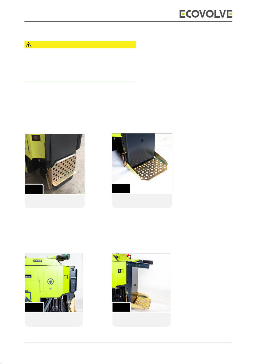
Operators platform
The truck has a 2 position platform for the operator to stand on when operating the machine.
In the raised position the operator can walk behind the truck (g 1). In the lowered position the
operator can operate the truck while standing on the platform (g 2).
The truck will default to walk mode speed (4 km/h) when the platform is in the raised position..
Overview
Safety rails
Every truck is equipped with foldaway safety rails for the protection of the operator.
Ensure that the safety rails are locked in the raised position when using the operators platform.
To lock the safety rails in place, raise the rails up and turn the lock to secure them (g 4).
The platform in the
raised position.
The platform in the
lowered position
FIG 2
FIG 1
The safety rails in the
lowered position. The safety rails locked
in the raised position.
FIG 3 FIG 4
5
Overview
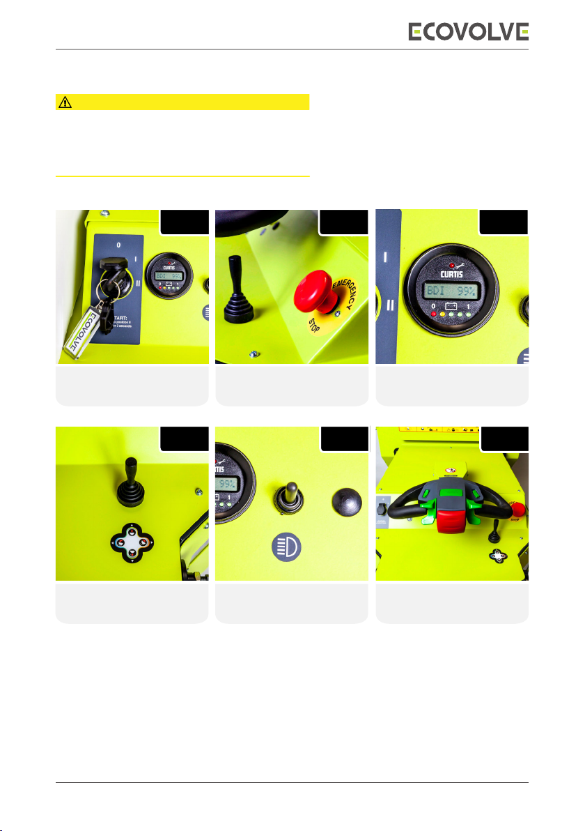
Dashboard controls
The following section is an overview of the
dashboard controls. All operators must read and
fully understand the instructions before operating the
truck.
CAUTION
Multi function display.
Battery discharge and
fault codes indicator.
FIG 1 FIG 2 FIG 3
Key ignition switch Emergency stop button.
FIG 4
FIG 5
Hi tip skip function lever. Light switch
Up = On | Down = O Tiller head steering
controller.
FIG 6

6
Overview
Flashing Beacon &
Motion Buzzer ON/OFF
Switch
Body Protection Switch.
Horn Switch: Pressed IN
will sound horn.
Traction paddles. Used
to drive the truck
Tiller head controls
The following section is an overview of the
tiller head controls.
All operators must read and fully understand the
instructions before operating the truck.
CAUTION
Traction paddles.
UP =Forward
DOWN = Reverse.
Speed Switch. Two
options SLOW and FAST.
FIG 7 Body Protection Switch.
As a safety feature, if the truck is being operated in reverse
and the operator collides with an object, their body will
engage the body protection switch (g 7).
This will automatically bring the truck to a stop and safely
move the machine forward.
FIG 1FIG 2 FIG 3
FIG 4 FIG 5FIG 6

7
Operation
Operating the truck
Switching on the truck
• Ensure the tiller head is in the central position and disengage the emergency stop button.
• Insert the key into the key switch and turn clockwise from the zero position
to position “II” and hold for 3 seconds. The traction wheel will reset and the multi function
display unit will display the battery discharge status.
• The electrical system is switched on and the truck is ready for operation.
Switching o the truck
• Ensure the truck is at a complete stop.
• Turn the key anticlockwise to the zero position.
• Activate the emergency stop button.
• The electrical system is switched o and the brake is applied.
Driving
• The operator must familiarize themselves with the tiller head steering controls and
traction paddles prior to driving the truck. The tiller head is used to steer the truck.
The traction paddles are used to accelerate the truck in a forward or reverse motion.
• To drive forward, the traction paddles are pressed upwards. When the traction paddles
are released the machine slows down to a standstill and the brakes are applied.
• To drive in reverse, the traction paddles are pressed downwards. When the traction
paddles are released the machine slows down to a standstill and the brakes are applied.
• The speed of the truck depends on set position of the speed control switch and if the
operators platform is in use.
Operating speeds
The truck has 3 operating speeds:
• Creeper mode under 1 kph: Engaged when the hi tip function is activated.
• Walking mode under 4 kph: Engaged when the operators platform is in the raised
position.
• Full mode 7 kph: Engaged when the operators platform is in the lowered position.
• The operator can also manually select the slower or faster speed using the speed switch
located on the tiller head.

8
Operation
Beacon
�For safety purposes the truck is equipped with a ashing beacon and motion buzzer.
�This can be activated using the switch on the left hand side of the tiller head.
Horn
�The horn is used as a warning signal, for instance at junctions and blindspots.
�The horn is situated on the top center of the tiller head.
Operating the hi tip skip functions
The truck is equipped with a high tip function.
The skip lever is located on the dashboard which
operates all the functions of the skip.
The skip lever functions in four positions:
�
Tilting the skip FORWARD:
Push the lever to the RIGHT.
�
Tilting the skip BACK:
Push the lever to the LEFT.
�
RAISE the skip:
Pull the lever BACK.
�
LOWER the skip:
Push the lever FORWARD.
Operating the Emergency stop button
�Press the emergency stop button to immediately shut down all powered functions.
Use the emergency stop button in the event of a malfunction of controls or a dangerous
situation.
�The emergency stop button is situated on the dashboard.
Emergency stop button in normal operation
�Pull the emergency stop button up.
The emergency stop button is unlocked.
The truck is ready for operation.
�Push the emergency stop button down.
The electrical system of the truck is switched o.
The driving, steering and lifting functions of the truck are deactivated.
The brake remains active.

9
Operation
Battery discharge indicator
�The battery’s discharge indicator (BDI) is the rate at which the battery discharges during the
operation of the truck. The operator can check the status of the battery by viewing the multi
function display (g 1). The display is located on the dashboard.
�The battery’s discharge status is shown on the display and is also indicated by the row of 5
LED’s situated below the display.
�As the battery capacity decreases, the digital display shows the BDI status from 100% to 0%.
Simultaneously the 5 LEDs turn o one after the other as the battery discharges.
�When the battery becomes critically low the truck will default to limp mode.
The operator must navigate the truck to the nearest charge point and recharge the battery
fully before continuing with work duties.
It is recommended to recharge the battery when the residual battery capacity is reading less
than 10% on the digital display.
BDI percentage:
�BDI percentage 90% and above - All 5 LEDs illuminated.
�BDI percentage between 70% and 90% - First 4 LEDs illuminated.
�BDI percentage between 50% and 70% = First 3 LEDs illuminated.
�BDI percentage between 30% and 50% = rst 2 LEDs illuminated.
�BDI percentage between 10% and 30% = First LED illuminated.
Multi function display.
Battery discharge and
fault codes indicator.
Parking
In the interest of safety, It is the operators responsibility to ensure that the truck is parked in a
safe and secure manner.
When parking the truck:
• The start key must be turned anticlockwise to “0” to turn o the truck.
• Activate the emergency stop button.
• The safety rails and platform should be put in the retracted position.
• If the truck is not in use for an extended period of time, it should be stored in a protected
area or indoors.
• If parking the truck on an incline, use the wheel chock provided as an added safety measure.
If the truck is switched on and unattended for a period longer than 9 minutes the machine will
automatically switch all power o.
FIG 1

10
Charging
The location of the battery
charging port at the rear of the
truck.
The location of the Delta Q
battery charger at the side of
the truck.
FIG 1 FIG 3
FIG 2
Connect the battery charging
cable into the charging port.
Never operate the truck while the battery is
charging.
WARNING
Charging the battery
�The battery charging port is located at the rear of the truck above the operators platform (g 1).
The dumper is supplied with a 3m charging cable.
�Ensure the truck is parked safe and securely, remove the key and activate the emergency stop
button prior to charging the battery.
�The truck is supplied with a 3m charging cable from the factory. Extension cords must be 3-wire
cord no longer than 30m (100’) at 10 AWG or 7.5m (25’) at 16 AWG, per UL guidelines.
�When charging the battery the operator must determine what power source is being used on
the work site, 110V or 220V. If in doubt ask the supervisor.
�The charging cable has a blue socket, this is to be plugged into the rear mounted charging port
at
the rear of the vehicle (g 2). The remaining plug is connected to the power source outlet
socket
.
�During the battery charging process, the battery charge status is displayed on the Delta Q
battery charger which can be viewed through a panel located at the side of the truck (g 3). A full
description of the battery charge indicator and all the other features of the Delta Q charger can
be found on page 11.
�When the battery is fully charged, remove the power cable from the power outlet a
nd the truck.
Power on the truck with the key to recommence work after the charge is complete.
11
Charging
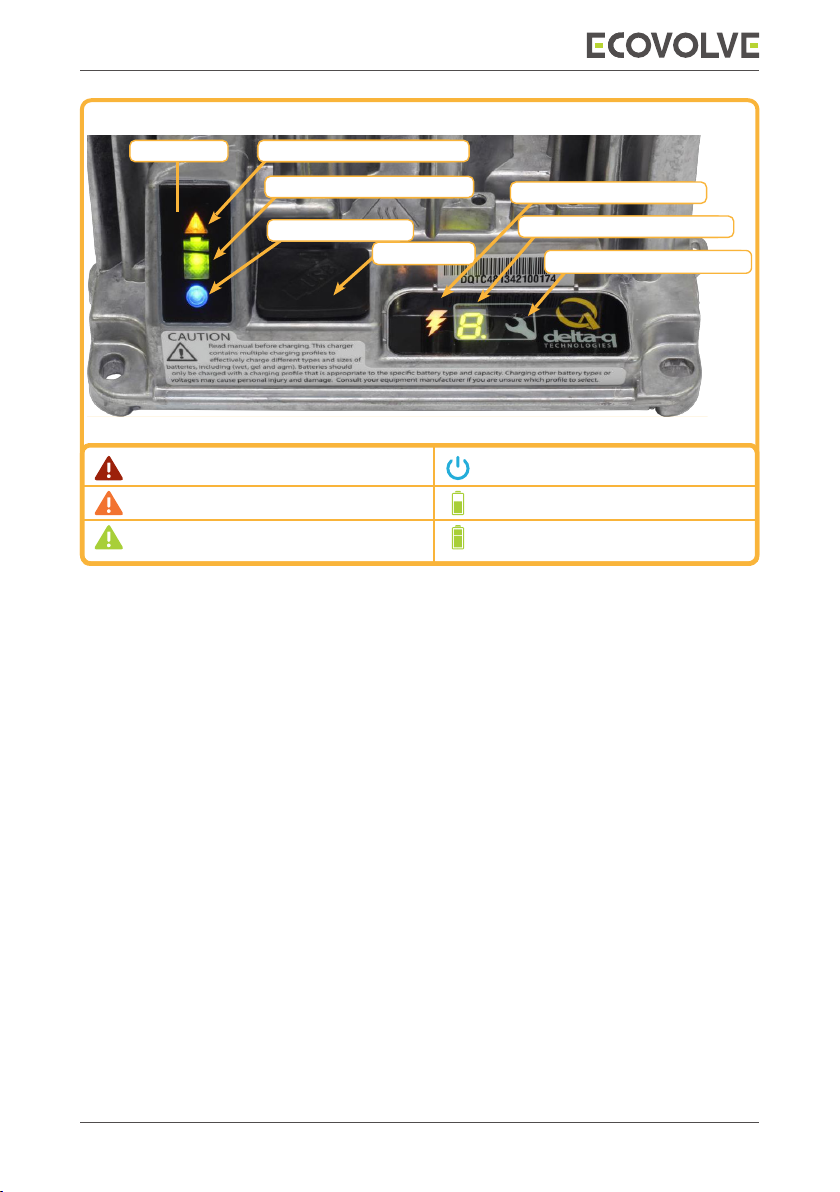
Delta Q IC1200 Battery charger overview
Display icons
1. The Fault / error /USB indicator will display faults, errors and USB activity shown in the
table above. If a fault or error is indicated check the (6.) error display panel for the code and
nd the description in the “charger error and fault codes” list below.
2. The Battery charging indicator has 4 states as shown in the table above.
3. The AC power indicator will illuminate solid blue when the charger is connected to AC power
4. The USB Host Port allows data to be transferred to and from the charger using a standard
USB ash drive, including the downloading of charge tracking data and updating of the
charger’s software and / or charge proles.
5. The Charging Output Indicator means that the charger output is active, and there is a
potential risk of electric shock.
6. The Charge prole / Error display panel shows one of four possible codes to indicate
dierent conditions:
�‘F’ codes meaning that an internal fault condition has caused charging to stop.
�‘E’ codes meaning that an external error condition has caused charging to stop.
�‘P’ code meaning that the charger programming mode is active.
�‘USB’ code meaning that the USB interface is active, the USB drive should not be removed.
�The ‘E,’ ‘F’ and ‘P’ codes will appear, then are followed by three numbers and a period
to indicate dierent conditions (e.g. E-0-0-4). See the “Charger Fault Codes” or
“Charger Error Codes” in the troubleshooting section of the owners manual
for details on these conditions and their solutions.
7. The Select charge prole button is used to select a charge prole from those stored on the
charger. Up to 25 charge proles can be stored. See the “Selecting A Charge Prole” in the
charger section in the owners manual for instructions.
1. Fault / Error / Usb indicator
AC Power indicatorAC Power indicator
2. Battery charging / Indicator
4. USB port
3. AC Power indicator
5. Charging output indicator
6. Charge prole / Error display
7. Select charge prole button
1. Solid red = Charger fault
View error display panel for details (6.)
1. Flashing green = USB port active
Solid green = safe to remove USB drive
1. Flashing amber = External error condition
View error display panel for details (6.)
3. Solid blue = AC power available
2. Flashing green = High state of charge
2. Solid green = Charge complete
2. Flashing green = Low state of charge
2. Solid green = High state of charge
IC1200 Display icons

12
Transportation
Transporting the truck
The Ecovolve ED1000 is easily transportable. It is comparatively lightweight for its capacity and
can
be loaded on to a vehicle with a load rating of 1300 kg minimum. The operator’s platform
can be raised up and the safety rails can be lowered down for ease of transportation.
• Use suitable ramps with an adequate loading capacity.
• Clean the truck to reduce the hazard of dirt and debris falling from the machine during
transport.
• Conrm the transport vehicle is suitable for the transport task and that it is rated to carry a
mass of 1300 Kg or 2866 lbs.
• Move the truck slowly and follow directions from people assisting with the loading and
alignment of the machine onto the transport vehicle.
• Secure the truck to the transport vehicle using only the machines anchor points as
described in the next section.
• Conrm that the lifting device has adequate lifting capacity and reach to perform the lifting
operation.
• Clean the truck to reduce the hazard of dirt and debris falling from the machine during
transport.
• Use only the lifting points as described in the next section to lift the truck onto a suitable
transport vehicle.
Keep clear when lifting the truck onto the transport
vehicle.
DANGER
When LIFTING the truck onto a suitable transporter
ensure that the following points are adhered to.
WARNING
When LOADING the truck onto a suitable transport
vehicle ensure that the following points are adhered to.
WARNING
13
Transportation
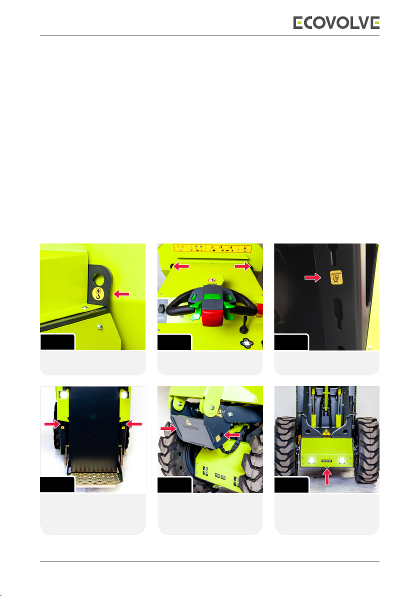
Lifting and anchor points
�The truck is equipped with two lifting eyes and ve anchor
points which are used in conjunction
with straps or chains to lift and also to secure the
machine to the transport vehicle.
�Use certied slings and chains to lift and secure the truck during transport.
�
The assigned lifting eyes and anchor points must
be used with approved straps or
chains. The
truck must be anchored at all times during transportation.
Lifting
�The two lifting eyes are designed so that the truck
can be lifted safely to a suitable transport
vehicle (g 1 and g 2).
�When using the lifting eyes it is advised to
use a ‘D’ shackle to connect them. This will povide
an
easier and more secure connection for the chain hooks
when lifting the truck.
Anchor
�The ve tie down points on the truck are designed to
anchor the truck to the transport vehicle
while in transit (g 3, 4, 5 and g 6).
The anchor points are
identied by this symbol.
FIG 1
The locations of the
anchor points on both
sides of the crank.
The locations of the two
lifting points on the truck.
The lifting points are
identied by this symbol.
FIG 5
FIG 3
FIG 2
The location of the anchor
point at the front of the
vehicle.
FIG 6
The locations of the anchor
points on each lower side
of the chassis at the rear of
the truck.
FIG 4

14
ED1000 Metric key measurements
and ground pressure
Ground pressure (Kg) D1 (Front) D2 (Rear) D3 (Front)
Unladen weight 1200 Kg 280 635 280
Laden weight 2000 Kg 650 700 650
Technical data
2610 1630 1470 1120 180 1310 2060 2390 340 1210 790 590
ED1000 2610 1630 1470 1120 180 1310 2060 2390 340 1210 980 780
280 kg 635 kg 650 kg
ED1500 2870 1790 1600 1120 200 1340 2250 2580 340 1330 1170 970
A1 A2 A3 A4 A5 B1 B2 B3 B4 C1 C2
Unladen Laden
700 kg
280 kg 635 kg 650 kg 700 kg
375 kg 750 kg 1125 kg 750 kg
D1/D3 D2 D1/D3 D2
Ground Pressure
A4
A3
A5
A2
A
A1
B4
B2
B1
B3
C2
C1
FrontRearFront
D1 D2 D3
Turning circle radius
1.6m
90°
steering angle
Driving (Db)
Buzzer [adjustable] (Db)
65
60-80
65
60-80
65
60-80
Output
Emission
Induction motor
5KW/7HP
Zero
5KW/7HP
Zero
5+4KW/11HP
Zero
Integrated Charging - Input (V AC)
- Output (V DC)
Recharge (Hrs)
100-240
50.0 A
8
100-240
50.0 A
8
100-240
100.0 A
10

15
ED1000 Imperial key measurements and ground
pressure
Ground pressure (Lbs) D1 (Front) D2 (Rear) D3 (Front)
Unladen weight 2634 Lbs 617 1400 617
Laden weight 4409 Lbs 1433 1543 1433
Technical data
2610 1630 1470 1120 180 1310 2060 2390 340 1210 790 590
ED1000 2610 1630 1470 1120 180 1310 2060 2390 340 1210 980 780
280 kg 635 kg 650 kg
ED1500 2870 1790 1600 1120 200 1340 2250 2580 340 1330 1170 970
A1 A2 A3 A4 A5 B1 B2 B3 B4 C1 C2
Unladen Laden
700 kg
280 kg 635 kg 650 kg 700 kg
375 kg 750 kg 1125 kg 750 kg
D1/D3 D2 D1/D3 D2
Ground Pressure
A4
A3
A5
A2
A
A1
B4
B2
B1
B3
C2
C1
FrontRearFront
D1 D2 D3
Turning circle radius
1.6m
90°
steering angle
Driving (Db)
Buzzer [adjustable] (Db)
65
60-80
65
60-80
65
60-80
Output
Emission
Induction motor
5KW/7HP
Zero
5KW/7HP
Zero
5+4KW/11HP
Zero
Integrated Charging - Input (V AC)
- Output (V DC)
Recharge (Hrs)
100-240
50.0 A
8
100-240
50.0 A
8
100-240
100.0 A
10

16
Daily checklist
It is the operator’s responsibility to report any faults or damage on the
truck to the site supervisor or relavent authority.
The operator’s weekly check list and the full service and maintenance
instructions for the truck are fully covered in the relevent sections of
the owner’s manual which can be found in the downloads section on
the ecovolve website - www.ecovolve.eu.
CAUTION
Operator’s daily check list
All operator’s must complete the daily checklist at the start of each working day prior to the
operation of the truck.
The truck must not be used if any item on the checklist is faulty or damaged.
Any faults or damage to the truck must be reported to the relevant authority.
1 Check for damage to bodywork and the chassis
2 Check the brakes and check the wheels and tyres for damage
3 All grease points are adequately greased
4 Inspect hydraulic hoses and connections for leaks
5 Speed switch function and horn
6 Traction paddles
7 Body protection switch
8 Multi function display is working correctly
9 All lights and motion buzzer
10 Emergency Stop button
11 All the functions of the skip lever
12 The operator’s platform and safety rails
13 The charging cable and connections
14 Check that all the front and rear wheel retaining nuts are tight
NOTE: Please refer to the servicing section (5) in the owner’s manual for information on the
specied torque settings on the front and rear wheel retaining nuts.
The owners manual can be found in the downloads section on the Ecovolve
website - www.ecovovle.eu.

CE Certicate

www.ecovolve.eu
Other manuals for ED1000
1
Table of contents
Other ECOVOLVE Construction Equipment manuals


