ECOVOLVE ED1500 Service manual

1
ED1500
ELECTRIC DUMPER
WWW.ECOVOLVE.EU
OPERATOR’S HAND BOOK

2
THIS OPERATOR’S HAND BOOK ONLY CONTAINS BA-
SIC INFORMATION for operating the ED1500. This opera-
tor’s hand book should be kept with machine at all time. A
full and comprehensive instruction guide may be found in
the Operator’s Manual supplied with the ED1500. The OP-
ERATOR’S MANUAL contains full information on the operational, main-
tenance, transportation and technical data for the ED1500.
Operator must read and understand the
OPERATOR’S MANUAL before operating the ED1500

3
SAFETY REGULATIONS
Always follow the warnings contained within this Operator’s Manual and on the
ED1500 to avoid incidents and accidents from occurring unnecessarily.
The following symbols and the signal words DANGER, WARNING, CAUTION,
and ELECTRICAL WARNING indicate hazards and instructions.
Warning Symbols
DANGER! / WARNING!
DANGER indicates a hazardous situation which, if not avoided, will
result in death or serious injury.
CAUTION!
CAUTION indicates a hazardous situation which, if not avoided, could
result in minor or moderate injury.
ELECTRICAL WARNING!
ELECTRICAL WARNING indicates a hazardous situation which, if not
avoided, could result in death or serious injury.
CRUSH POINT WARNING!
MOVING PARTS WARNING indicates a hazardous situation which, if
not avoided, could result in death or serious injury.
WHEEL CRUSH WARNING!
WHEEL CRUSH WARNING indicates a hazardous situation which, if
not avoided, could result in serious injury. Obey all safety messages
that follow this symbol to avoid injury.
Operators Personal Protective Equipment (PPE)
SAFETY SHOES REQUIRED
Safety shoes must always be worn when operating the ED1500 to
avoid personal injury.
For all other (PPE) follow the guidelines issued by the specic site you are
operating the ED1500 on.
4
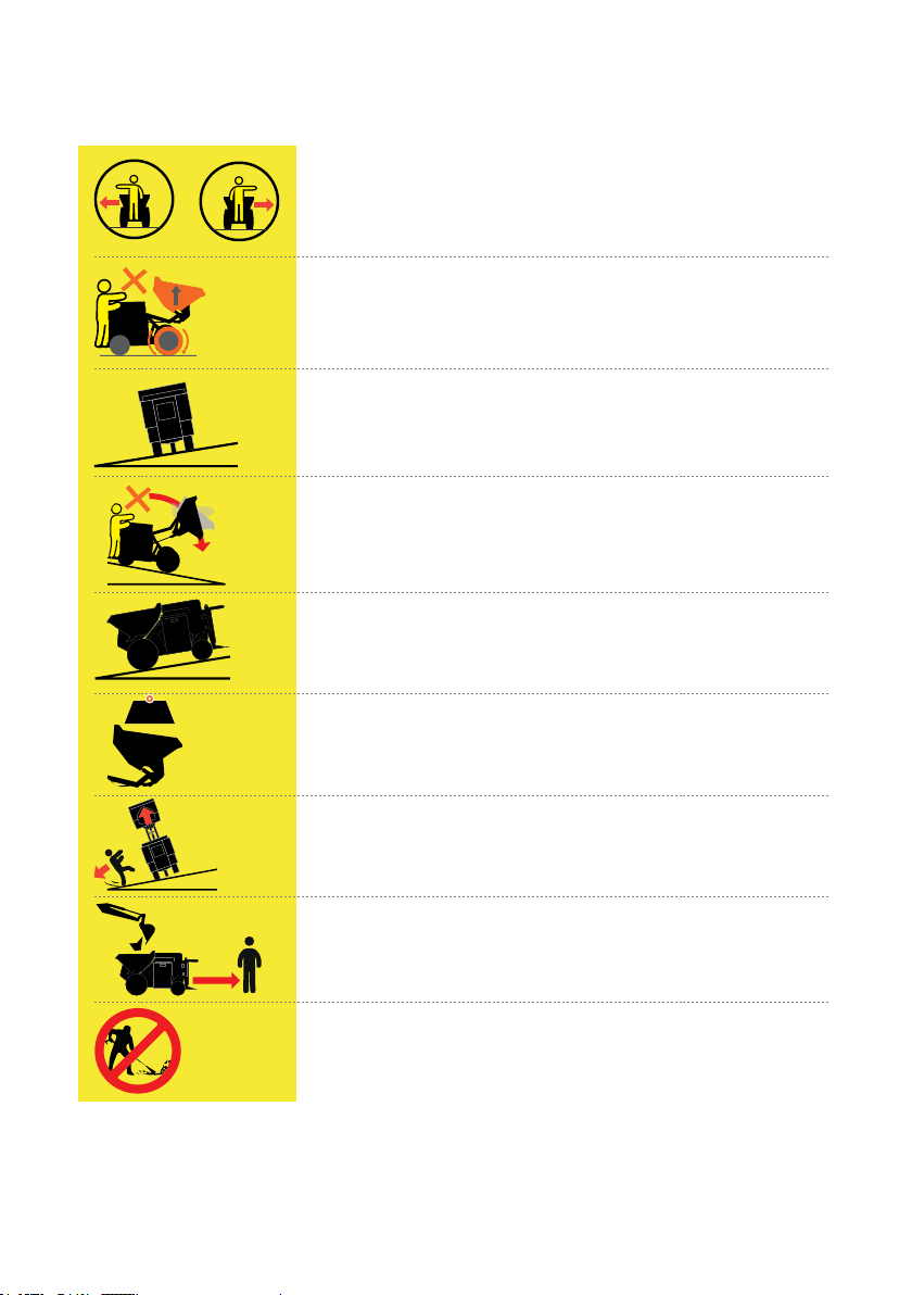
SKIP STICKER WARNING SYMBOLS
Indicate change of direction by using hand signals.
Danger! Don't drive with the skip in the raised position
Max 10° Danger! Risk of over turning on Max Gradient 10°
Danger! High level of risk which could result in death or seri-
ous injury if they are not avoided.
Max15° Drivable uphill/downhill Max Gradient 15°
Warning! Don’t exceed the max load rating 1500kg / 3306
Lbs
Danger! When unloading the skip in the raised position.
Keep clear of the risk zone
DANGER! stand clear while being loaded
Do NOT power wash
10 max
o
15 max
o

5
TABLE OF CONTENTS
3 SAFETY REGULATIONS
4 SKIP STICKER WARNING SYMBOLS
6 TILLER CONTROLS
7 DASH CONTROLS
9 OPERATOR’S SAFETY RAILS & PLATFORM
10 CHARGING
10 STEERING & PARKING
12 TRANSPORTATION OF MACHINE
13 LIFTING & ANCHOR POINTS
15 OPERATOR’S DAILY/WEEKLY CHECK
16 METRIC KEY MEASUREMENTS AND GROUND
PRESSURE
17 IMPERIAL KEY MEASUREMENTS AND GROUND
PRESSURE
18 ED1500 EUROPEAN CE CERTIFICATE
6
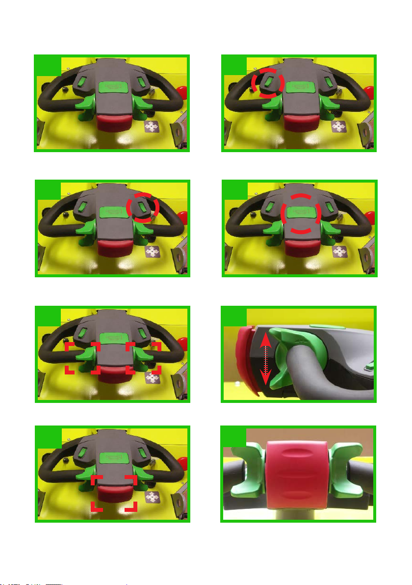
TILLER CONTROLS
Tiller in start position. (Fig 2) Beacon Light & Motion buzzer ON/
OFF switch. (Fig 3)
2
Speed Switch. Two options high and
low (Fig 4) Horn. (Fig 5)
3
4 5
6 7
89
Traction paddles. UP forward /DOWN reverse. (Fig 6-7)
EMR REVERSE – When Pressed IN will STOP the ED1500, and move it forward away
from danger. (Fig 8-9)

7
DASH CONTROLS
Multi-functional display. Displays battery discharge (BDI), hour meter and error
messages.(Fig 10)
10 11
Multi-functional display metre. (Fig 10) Light switch. (Fig 11)
Key start. To power up the ED1500, rst check that the emergency stop button is in the
UP position, then turn the start key clockwise. (Fig 12)
12

8
13 14
Emergency stop button.(“E-stop”)
Press the E-stop button to immediately interrupt all powered functions. Use the E-stop
during operation if the travel or skip functions do not respond normally to operator
commands. (Fig 13-14)
OFF POSITIONON POSITION
Skip lever.
The skip lever has four positions.
1. pull the lever back to raise the skip.
2. push the lever forward to lower the skip
3. push the lever to the right to tilt the skip out
4. push lever to the left to tilt skip in. (Fig 15-16)
15
RAISE LOWER
16
TILT IN TILT OUT
9
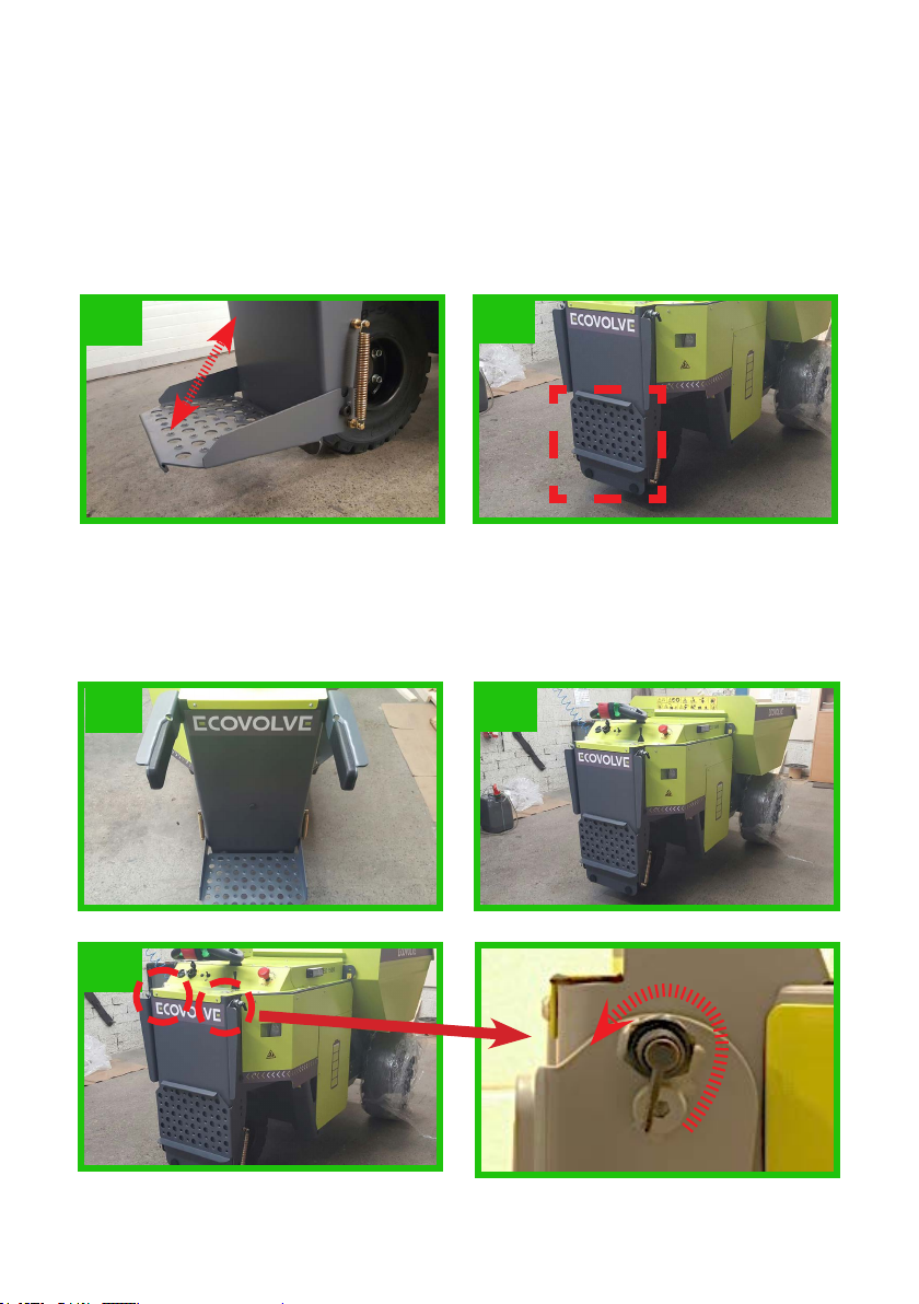
OPERATOR’S SAFETY RAILS & PLATFORM
Operator’s platform
In the down position the operator can operate the ED1500 standing on the platform, in
the up position the operator can walk behind the ED1500. (Fig 17-18)
Ride on mode: Operators platform Must be in the Down position.
Walk mode: Operators platform Must be in the Up position.
17 18
Operator’s safety rails
For the operators safety the dumper is tted with two retractable rails as shown.(Fig 21)
Ride on mode: Safety rails Must be in the Up position.
Walk mode: Safety rails Must be in the Down position. (Fig 19-21)
SAFETY RAIL LOCK
19 20
21

10
CHARGING
Charging
When charging the ED1500 the operator
must determine what power source is being
used on the work site 110V or 240V. If
in doubt, ask the supervisor. Both the
110V and the 240V charging cable has a
blue coupler, this is to be connected to the
ED1500 charging point rst and then the
remaining plug is plugged in to the power
source outlet socket. (Fig 24-26) Charging
the battery is covered in chapter 6 of the
Operator’s manual.
To ensure maximum performance and life of AGM battery. Charge the battery pack
fully before use.
STEERING & PARKING
Steering
The tiller head of the ED1500 can move from left to right as required when steering the
ED1500, this will turn the traction wheel in the direction desired. (Fig 27)
24
25 26
27
11
Parking
In the interest of safely parking, it is the operator’s re-
sponsibility to ensure the ED1500 is parked in a safe
manner and not obstructing other trafc or people.
When parking the ED1500,
• The start key must be turned anticlockwise to
power off, and removed from the machine.
• The E-stop button must be pushed in to the off po-
sition, to further ensure isolation of the machine.
(Fig 14)
• The Safety arms and the Step should be put in the
retracted position.
• If parking for long periods of time, the ED1500
should be in a sheltered area or indoors.
• If parking on an incline, use the chock provided.
(Fig 35)
Greasing
The ED1500 is tted with 17 grease nipples which can be located at all moving joint.
To grease simply remove the grease nipple dust cap. (Fig 36)
Give each point 1 squirt of grease and replace dust cap.
35
36

12
TRANSPORTATION OF MACHINE
The ED1500 is easily transportable. The operator’s platform and side supports
can be folded down for ease of transportation.
WARNING!
When LOADING the ED1500 on a suitable vehicle ensure that the following points are
adhered to.
• Clean the ED1500 to reduce the hazard of dirt and debris falling from the machine
during transport.
• Conrm that the transport vehicle is serviceable for the transport task and that it is
rated to carry a Mass of 1.5 tons or 3306 Lbs
• Move the ED1500 slowly and follow directions from people assisting with loading
and alignment on the transport vehicle.
• Secure the ED1500 to the transporter using only the ED1500s anchor points.
WARNING!
When LIFTING the ED1500 on to a suitable transporter ensure that the following points
are adhered to.
• Conrm that the lifting device has adequate lifting capacity and reach to perform the
lifting operation.
• Clean the ED1500 to reduce the hazard of dirt and debris falling from the machine
during lifting.
• Use ONLY the lifting points as described in this chapter 8.3 to lift the ED1500.

13
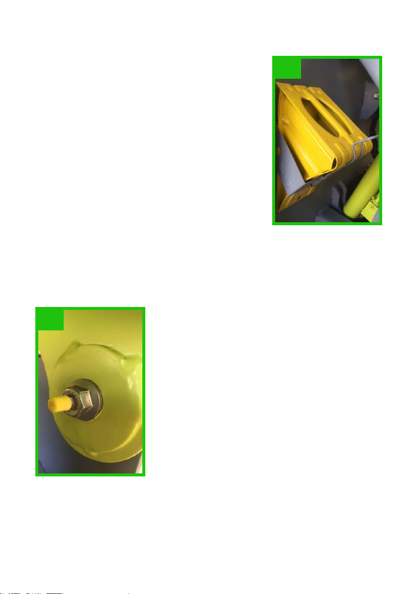
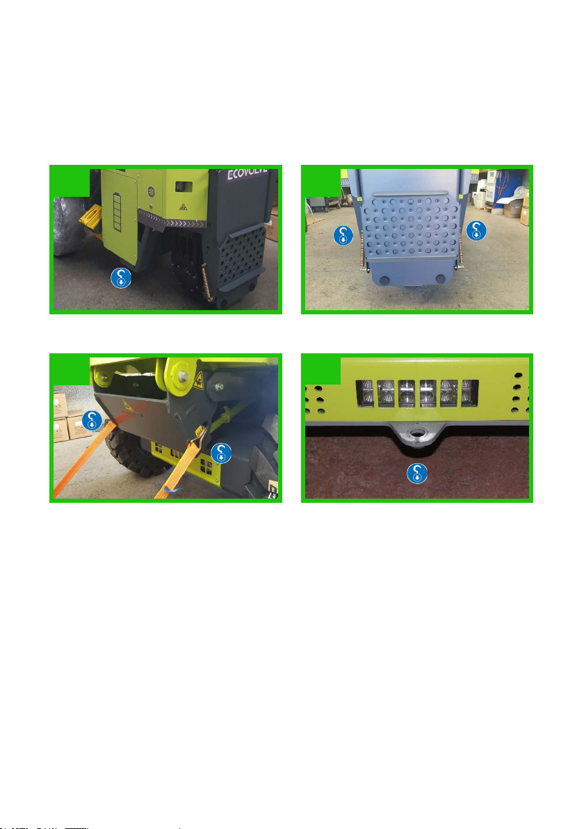
LIFTING & ANCHOR POINTS
The unladed weight of the dumper is 1500kg /3306Lbs.
The ED1500 has two lifting points (Fig 28) and ve anchor points which are used to lift
and secure the machine when transporting. The two lifting points, as indicated below
are designed so that the machine can be lifted safely on to a suitable transporter. The
ve anchor points are designed to anchor the machine. The assigned lifting and
anchor points must be used in conjunction with approved straps or chains. At all times
in transportation the ED1500 must be anchored.
Lifting
When using the lifting eyes, it is advised
to use a “D” shackle Fig 29 to connect
securely to them, this gives easier safe
connection for the chain hook when lifting.
Fig 30.
28
29 30
14
Anchor
While being transported it is important to ensure the ED1500 does not move, the ve
anchor points provided should be used to best effect, front and back of the machine,
using certied slings and chains. See Fig 31-34.
31 32
33 34

15
OPERATOR’S DAILY/WEEKLY CHECK
1. Charger status
2. E-Stop.
3. Hydraulic Hoses and Couplers for Leaks.
4. Operators Platform and Safety Rails
5. Body protection switch.
6. Dash display is working correctly.
7. All Function Test.
8. The function of the toggle switch.
9. Buzzer and Sounder.
10. Check for Damages.
11. Check for Lubrication.
It is the operator’s responsibility to report any
faults observed to the site supervisor. The op-
erator’s weekly check list is covered under rele-
vant section of the Operator’s manual supplied
with the Ed1500.
16
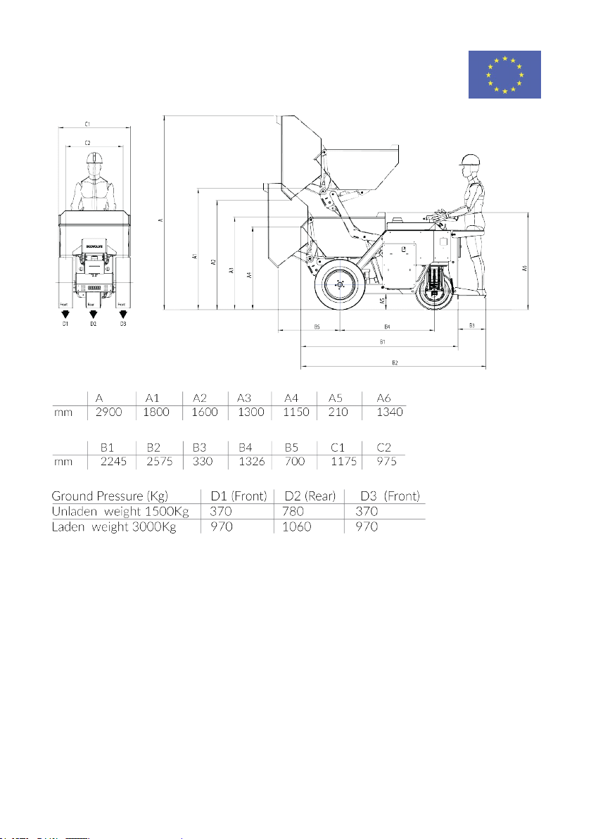
METRIC KEY MEASUREMENTS AND
GROUND PRESSURE
17
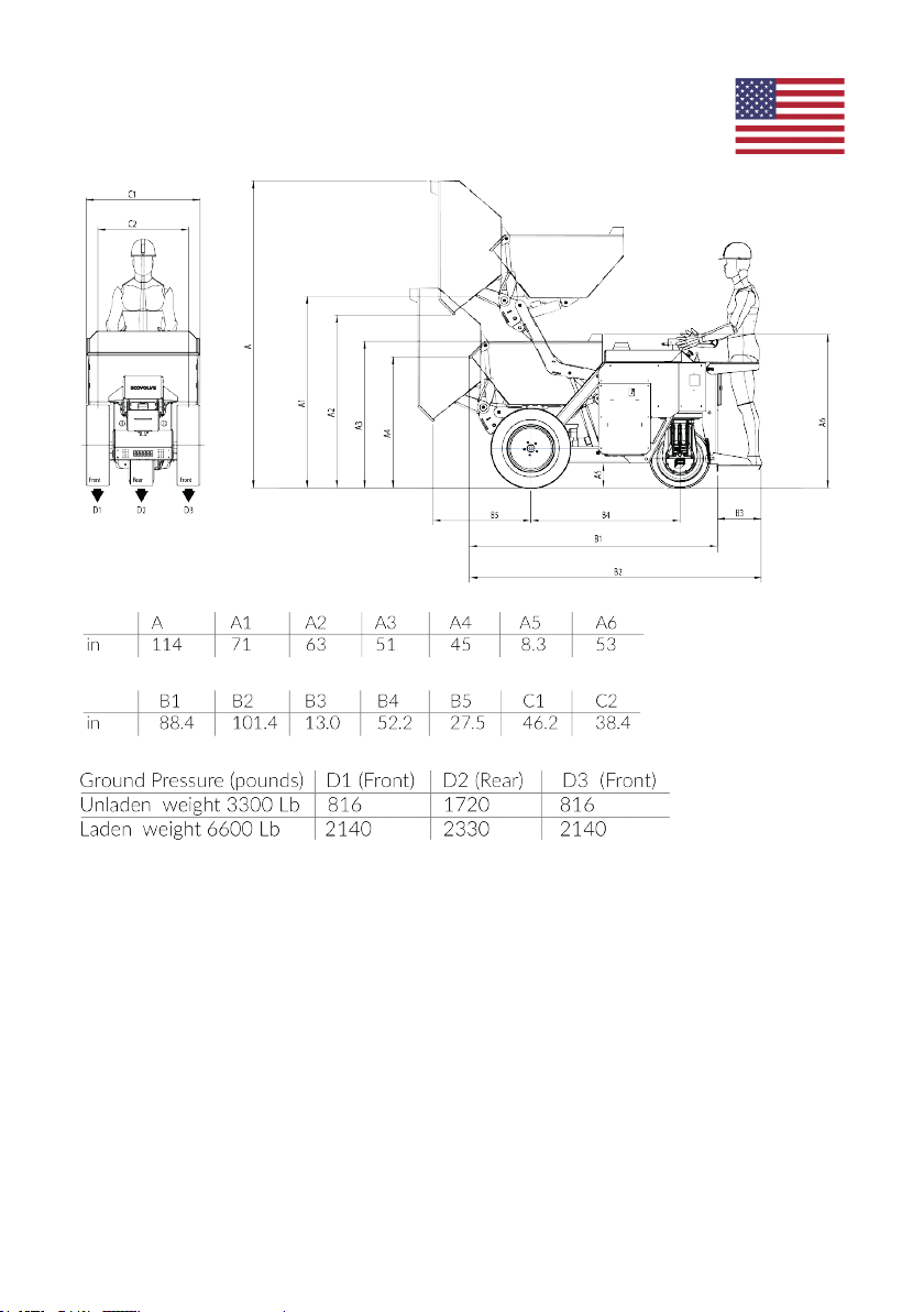
IMPERIAL KEY MEASUREMENTS AND
GROUND PRESSURE
18
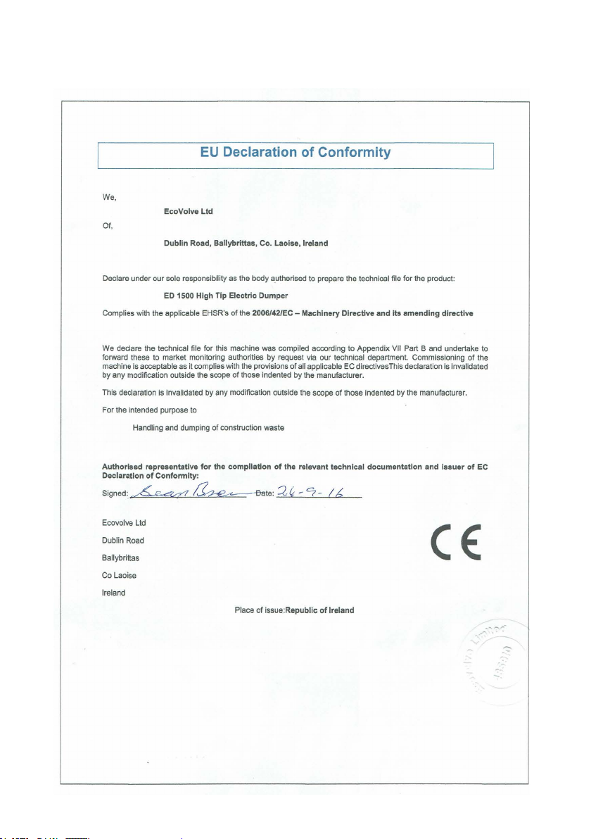
ED1500 EUROPEAN CE CERTIFICATE
Table of contents
Other ECOVOLVE Construction Equipment manuals


Popular Construction Equipment manuals by other brands

HYVA
HYVA HC501 WARNING, OPERATING AND MAINTENANCE MANUAL

Manitowoc
Manitowoc National Crane NBT50 Series Operator's manual

Toro
Toro 68037 Operator's manual

Watts
Watts BLUCHER 760 0 Series installation instructions

nokka
nokka 2051P Installation, operation and maintenance manual

HIAB
HIAB 190TM Operating manual / spare parts list


