EcoxGear SOUNDEXTREME SEI-SETXLED User manual

User Guide
LED Rocker Switch
Remote Control
Model: SEI-SETXLED

2
· Please read this User Guide before installation and use.
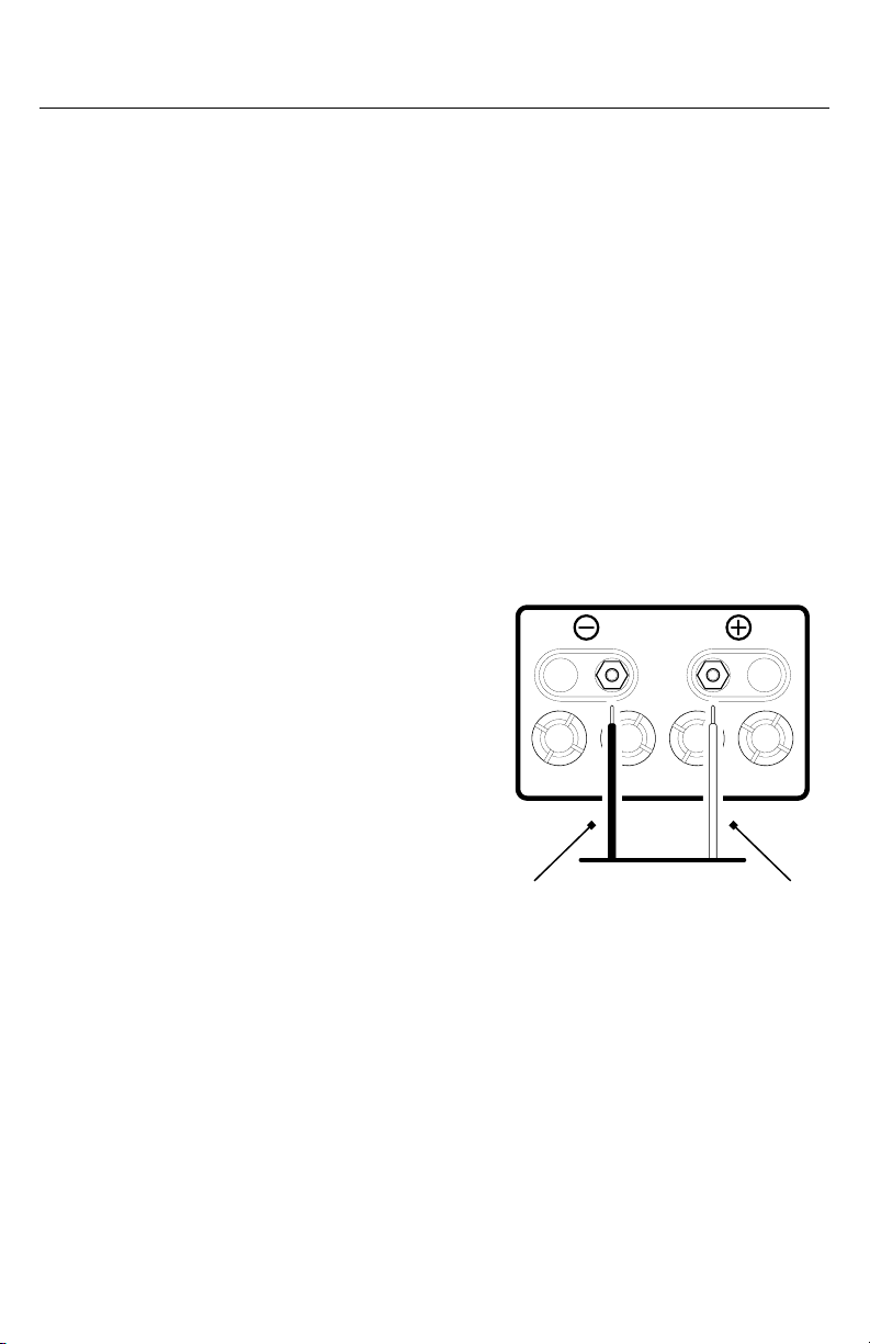
· CAUTION: The power input voltage range for your LED Rocker
Switch Remote Control (referred to as Switch) is 9V to 16V. It
is designed to work with a +12V DC battery power supply. If
your vehicle battery power output is not 12V (e.g., 24V, 36V, or
48V), you will need a voltage converter with 12V output (e.g., a
48V-to-12V converter). Connecting the Switch directly to higher
voltages will cause damage to your device and VOID THE
PRODUCT WARRANTY.
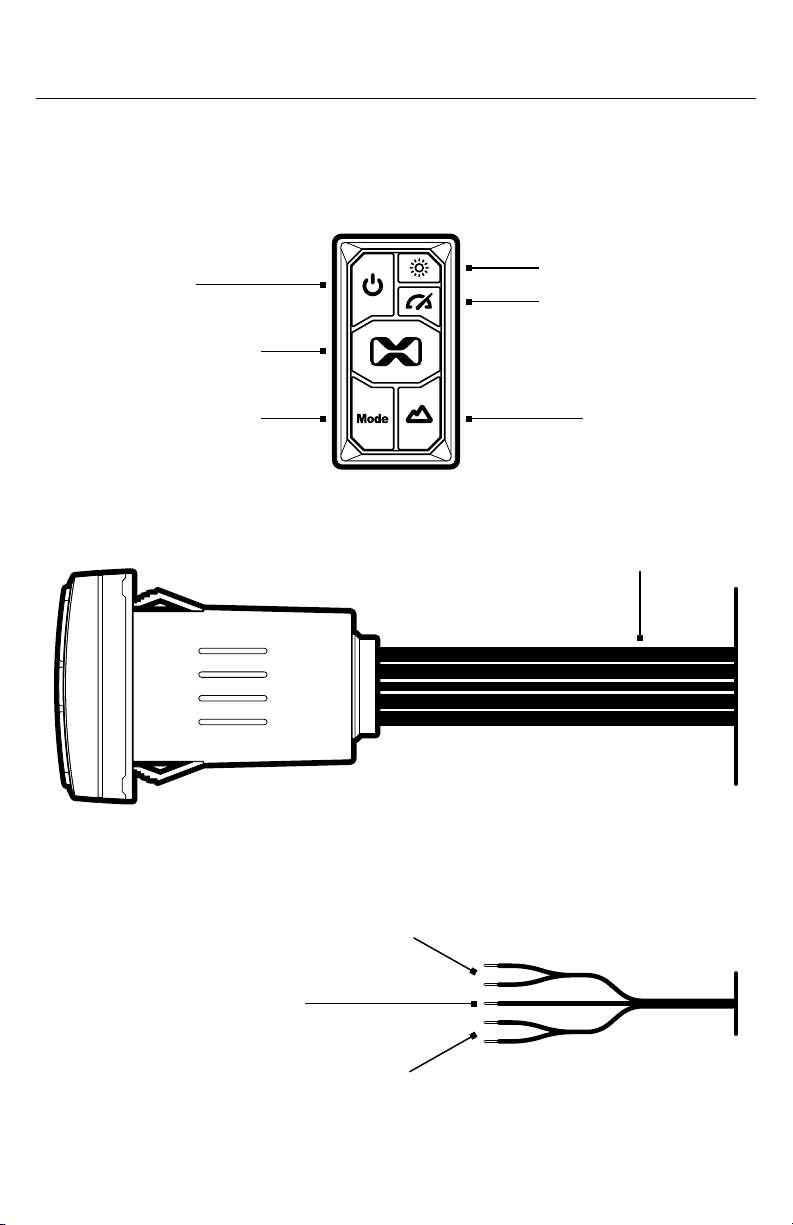
· The Switch has a built-in RF remote transmitter that will operate
the LED lights on a wirelessly paired, LEDCast-enabled
SoundExtreme product. This Switch only controls LED light
functions, not audio. It is optimized for the ExtremeController
(a 4-Zone LED Controller by SoundExtreme). To control the
audio functions as well as basic LED controls of SoundExtreme
soundbars, speakers, and radios, please purchase the Audio
Rocker Switch Remote Control. Visit www.soundextreme.us for
more details.
· The Switch fits in a standard Carling rocker switch opening, which
is commonly used in the dashboard of many o-road vehicles,
boats, and golf cars. The Switch panel is waterproof; however, the
housing behind the panel is only splash proof.
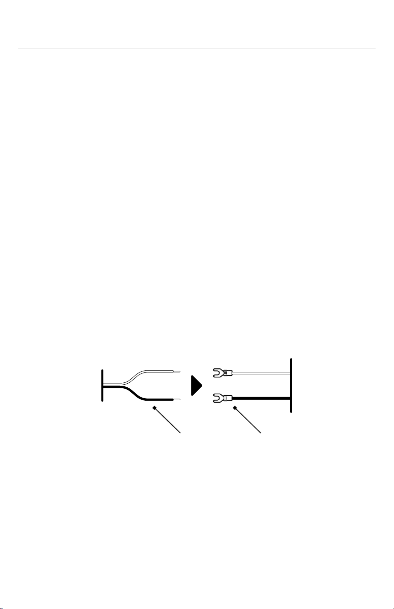
· CAUTION: In order to make sure there is no potential damage to
your audio system, unplug or power o your audio equipment until
after all connections are completed.
Important

3
Introduction
Features
The Switch is an all-in-one device providing power and wireless LED
lighting controls to a paired SoundExtreme product.
Remote Turn-On Output
In addition to opperating as a power switch, the Switch also has a
+12V Remote Turn-On signal output, which can be connected to an
ExtremeController’s Remote Turn-On Input. That ExtremeController
can then be automatically turned on or off when you turn the Switch
on or off.
RF Remote Transmitter
The Switch has a built-in RF 433MHz remote transmitter, which
is used to pair with and control an ExtremeController or other
LEDCast-enabled SoundExtreme product. The first time you use the
Switch, you will need to pair it with a product. Once they are paired,
your product will remember your Switch. Next time you power on
your product, your Switch's remote functions will be ready to use.
Lighting Control Concepts
Below are some terms and definitions to help you better
understand the Lighting Control Concepts associated with the
ExtremeController and other LEDCast-enabled SoundExtreme
products. Please refer to the ExtremeController User Guide for
more details.
Zone
A Zone corresponds to all the LED lights that are connected
directly to one physical connection on an LED Lighting Controller
output. When you change a Zone status (on / o, Mode, etc.), the
LEDs connected to that Zone will change accordingly. Depending
on the product the Switch is paired with, the SoundExtreme product
may have 1 to 4 LED lighting Zones.

4
Introduction
Mode
There are 3 LED Mode categories, totaling in 44 Modes supported
by the Switch's RF remote control:
· 8 Color Mode
· 20 Party Mode
· 16 Music Mode
Scene
A Scene is programed via the SoundExtreme Smartphone App.
You can customize each Zone into a Scene (a preset). Setting the
Scenes on the app allows a 1-button press to bring up your desired
custom settings for all of the LED products connected to the LED
Lighting Controller. LEDCast-enabled SoundExtreme products
have 5 Scene settings.

5
Switch Layout
Switch Overview
Power Button
All Zones Button
Mode Button
Brightness Button
Speed Button
Scenes Button
Inputs and Outputs
Power Inputs:
+12V Wire (Red) / GND Wire (Black)
Accessory Outputs:
+12V Wire (Red) / GND Wire (Black)
Remote Turn-On Output
Wire (Dark Blue)

6
Switch Overview
Connectors
Input:
· Power Input: +12V, GND – Connect to your vehicle's +12V battery.
Only connect to a +12V DC power supply.
Outputs:
· Remote Turn-On Output: +12V signal output when the Switch is on.
· Power Outputs: +12V, GND – Connect to a SoundExtreme
product's power input (maximum current not exceeding 20A, 12V).
Button Functions
Power Button
· Press and hold for 3 seconds to turn the Switch on or o.
· When the Switch is on, short-press to turn the button backlights on
or o.
· When the Switch is on, double-click to enable RF Remote Pairing
with a SoundExtreme product.
Brightness Button
· Short-press to cycle through 5 levels of LED brightness for all of
the Zones.
Speed Button
· Short-press to cycle through 5 levels of LED lighting speed for all
of the Zones, while in a Party Mode.
All Zones Button
· Short-press to turn all of the Zones on or o.

7
Switch Overview
Mode Button
· Short-press to cycle through all of the LED lighting Modes for all of
the Zones.
Scenes Button
· Short-press to cycle through 5 predefined LED lighting Scenes.

8
Installation and Wiring
Installing Your Switch Onto Your Vehicle
The Switch is designed to snap into a standard Carling style rocker
switch opening.
· If you already have that style of an opening on your vehicle, you can
simply snap the Switch into place.
· If your vehicle doesn’t already have that style of an opening, you
will need to cut a rectangular hole into your vehicle. Before you cut,
please refer to the dimensions under the Specifications section to
determine the cutout size.
Connecting to an External Speaker
If you want to provide power to and control an external
ExtremeController's or other LEDCast-enabled SoundExtreme
product's power on and o feature, you will need to connect it to the
Switch's Accessory Power Outputs and Remote Turn-On Ouput.
Accessory Power Outputs
Connect the Switch's Accessory Power Outputs (+12V and GND) to
the power inputs on the ExtremeController you want to control.
· Make sure that the Switch's RED +12V Wire is connected to the
ExtremeController's RED Wire and the Switch's BLACK GND Wire
is connected to the ExtremeController's BLACK Wire.
Switch's Accessory
Power Outputs
SoundExtreme Product
Power Inputs

9
Installation and Wiring
Remote Turn-On Output
Switch's Remote
Turn-On Output Wire
SoundExtreme Product
Remote Turn-On Input Wire
Besides the 12V power supply, the Switch has an optional
Remote Turn-On Signal Output to turn on and power o the
ExtremeController or LEDCast-enabled SoundExtreme product
you want to control. The output voltage is 12V.
If your SoundExreme product has a Remote Turn-On Input, follow
the steps below:
1. Connect the Switch's (Dark Blue) Remote Turn-On Output Wire
to the ExtremeController's Remote Turn-On Input. You may need
an extension cable (supplied with the ExtremeController).
2. Once the connections are completed, the ExtremeController will
automatically turn on or o when the Switch is turned on or o.

10
Installation and Wiring
Connecting to 12VDC Power Supply
When you install the Switch to a battery or a voltage regulator on
a golf cart, a boat, a quad bike, a UTV, or another vehicle, you need
to make sure that your vehicle battery or battery pack terminal
voltage is 12VDC. If the battery terminal voltage is not 12V, you will
need a DC–DC converter with output 12V. Connecting the Switch
to a non-12VDC power source will lead to a malfunction or damage
to the Switch.
Recommendation: If you are not familiar with all of the vehicle’s
battery or ignition switch connections, consult your vehicle’s
manual or a technician. Incorrect connections to your vehicle’s
battery or ignition signal terminal may cause damage to your
speaker and your vehicle.
Connect the +12V and GND wires
to the 12VDC power supply.
· Make sure that the RED Wire
is connected to +12V battery’s
positive (+) terminal and the
BLACK Wire is connected to
battery’s negative (-) terminal.
WARNING! Only connect to a 12V
power supply. Do NOT connect to
a 24V, 36V, or 48V power supply.
Connecting the Switch directly to
these higher voltages will cause
damage to the Switch and VOID
THE PRODUCT WARRANTY.
Black Wire Red Wire

11
Audio Functions
First Time RF Remote Pairing
The first time you use the Switch, you will need to pair the Switch with
an ExtremeController or other LEDCast-enabled SoundExtreme
product. This process is only needed for the first time you use the
Switch with a product.
Please follow the steps below for first-time pairing:
1. Press and hold the Power Button to turn the Switch on.
2. If you are pairing with an ExtremeController, the ExtremeController
will automatically enable remote pairing when turned on. If you
are pairing with another SoundExtreme product, you may need to
enable RF remote pairing on your SoundExtreme product.
Example: On a SoundExtreme Elite Soundbar, press and
hold both the and Buttons on the Soundbar at the same
time for 3 seconds. The Soundbar's LED Party Lights will flash
Green, indicating it is ready to pair with a remote.
3. On your Switch, double-click the Power Button . Your Switch
will start pairing.
4. Once paired, the LED Party Lights connected to the
ExtremeController will rapidly flash Green 3 times, indicating a
successful pairing.
Note: The paired product may produce a dierent prompt to
indicate a successful pairing. Please refer to the product's
User Guide.
5. Now you can press a button on the Switch, such as the All Zones
Button, to check if your ExtremeController responds.

12
Specifications
Unit Weight
4.59 oz (130 g)
Power Input
9~16V, 20A
Power Output
9~16V, 20A
Dimensions
0.82 in / 21 mm
0.64 in / 16 mm
1.89 in / 48 mm
2.1 in / 53 mm
1.02 in / 26 mm
1.96 in / 50 mm
2.74 in / 70 mm
1.3 in / 33 mm
1.63 in / 42 mm
Remote Turn-On Output
12V, 1.2mA
Storage Temperature
-40°F to 122°F / -40°C to 50°C
Operating Temperature
23°F to 95°F / -5°C to 35°C

13
FCC STATEMENT:
This device complies with Part 15 of the FCC Rules. Operation is subject to the following two conditions:
1.) This device may not cause harmful interference, and
2.) This device must accept any interference received, including interference that may cause undesired operation.
WARNING: Changes or modifications not expressly approved by the party responsible for compliance could void the
user’s authority to operate the equipment.
NOTE: FCC's RF Exposure guidelines, this equipment should be installed and operated with minimum distance
between 20cm the radiator to your body.
This equipment has been tested and found to comply with the limits for a Class B digital device, pursuant to Part 15 of
the FCC Rules. These limits are designed to provide reasonable protection against harmful interference in a residential
installation. This equipment generates, uses, and can radiate radio frequency energy and, if not installed and used
in accordance with the instructions, may cause harmful interference to radio communications. However, there is no
guarantee that interference will not occur in a particular installation. If this equipment does cause harmful interference
to radio or television reception, which can be determined by turning the equipment o and on, the user is encouraged
to try to correct the interference by one or more of the following measures: reorient or relocate the receiving antenna,
increase the separation between the equipment and receiver, connect the equipment into an outlet on a circuit dierent
from that to which the receiver is connected, consult the dealer or an experienced radio/TV technician for help.
RF WARNING STATEMENT:
The device has been evaluated to meet general RF exposure requirement. The device can be used in portable
exposure condition without restriction.
IC STATEMENT:
This device complies with Industry Canada licence-exempt RSS standard(s). Operation is subject to the following two
conditions:
1.) This device may not cause interference, and
2.) This device must accept any interference, including interference that may cause undesired operation of the device.
PRODUCT USE AND PROTECTION:
Read and follow all instructions. Use only as intended.
The SoundExtreme unit is intended to be used indoors or outdoors and in land or water environments. The unit has
been tested to IP66 waterproofing standards, which means the unit can be exposed to dust and water, but should NOT
be submerged underwater.
To prevent fire or shock, do NOT attempt to power this unit if it is wet or you suspect water has entered the unit. In this
situation, please return the unit to SoundExtreme for a free assessment. If we have found that the unit has carried
water, we will repair or replace the unit free of charge.
SAFETY ADVISORY & WARNING:
Read and follow all instructions. Use only as intended.
CAUTION: Do NOT open to repair. A qualified technician must carry out repair work.
ATTENTION: Do NOT connect to a SoundExtreme product with LEDCast technology while the unit is wet. Make sure
all connections are dry BEFORE connecting to a power source. Failure to do so may result in electrical
damage to the unit and may void the warranty.
WARNING: Cancer and Reproductive Harm - www.P65Warnings.ca.gov
ATTENTION: Do NOT dispose of in a landfill. Contact SoundExtreme at www.gracesupport.com or a certified
recycling agent to dispose of the unit.
SAFETY:
This product has a limited life span of use and should be replaced when it shows obvious signs of wear.
Do not modify or remove any original component parts of the speaker. Doing so could cause damage to the unit,
allowing water to ingress. A unit with water ingress should not be charged due to potential risk of fire or shock.
Please exercise care and good judgment when using your SoundExtreme unit.
You should always
1.) Return the unit to SoundExtreme if you suspect water ingress into the unit or if the unit has experienced a severe
impact that may have aected the integrity of the unit to take on water.
Important Legal Information

14
You should never
1.) Never power your SoundExtreme unit if you suspect water has entered the device. Powering a device with water
inside could be potentially hazardous and cause fire or a spark.
2.) Never use your SoundExtreme unit if you have dropped it or thrown it against a hard surface which may have
destroyed the integrity of the housing. In the event of a severe impact to your unit, please return the unit to
SoundExtreme to review for potential damage.
3.)Never attempt to fix, repair your SoundExtreme unit . Please send it back to SoundExtreme for any assessments
and repairs.
CARE, MAINTENANCE & PRECAUTIONS:
1.)Do NOT apply excessive force to any surfaces of the unit.
2.)Do NOT use or store the unit in places with high temperature.
3.) AVOID prolonged exposure to ultraviolet radiation (UV sunlight) and strong magnetic fields.
LIMITED MANUFACTURER’S WARRANTY:
The Switch is covered by a 1-year limited warranty that covers defects in workmanship and / or materials for
a period of 1 year from original purchase date. This warranty does not apply to any products which have been
abused, neglected, modified or used for a purpose other than the one for which they were manufactured. Please
refer to the above care and maintenance instructions for suggested care details. The warranty is valid only for the
original owner who purchases the unit from an authorized dealer. Transfers do not qualify for warranty protection.
SoundExtreme reserves the right to replace any out-of-stock or discontinued product with a comparable product.
Discontinued products may not be available for warranty replacement. Any contents are NOT covered by the limited
manufacturer’s warranty. Warranty terms may be revised without notification at the discretion of the manufacturer.
Please visit www.soundextreme.us for additional product & warranty information.
LED Rocker Switch Remote Control by SoundExtreme Inc., Houston, Texas.
Designed in Texas. Made in China.
Important Legal Information

15
EXTREME INNOVATION
for YOUR LIFESTYLE
soundextreme.us

16
What’s in the Box
LED Rocker Switch
Remote Control
User Guide
User Guide
LED Rocker Switch
Remote Control
Model: SEI-SETXLED
Table of contents
Other EcoxGear Remote Control manuals
Popular Remote Control manuals by other brands

Jøtul
Jøtul GI 160 BF Installation and operating instructions

Byron
Byron Home Easy HE-310 installation instructions

Lennox
Lennox RG51Q/BGE manual

Home
Home URC 4 instruction manual

Flying Industry Development
Flying Industry Development 0020481 quick guide

Mitsubishi Electric
Mitsubishi Electric PAC-SF44SRA installation manual