Sealey BT91/10.V3 User manual

6/12V HANDHELD BATTERY TESTER
MODEL NO: BT91/10.V3
Thank you for purchasing a Sealey product. Manufactured to a high standard, this product will, if used according to these
instructions, and properly maintained, give you years of trouble free performance.
IMPORTANT: PLEASE READ THESE INSTRUCTIONS CAREFULLY. NOTE THE SAFE OPERATIONAL REQUIREMENTS, WARNINGS & CAUTIONS. USE
THE PRODUCT CORRECTLY AND WITH CARE FOR THE PURPOSE FOR WHICH IT IS INTENDED. FAILURE TO DO SO MAY CAUSE DAMAGE AND/OR
PERSONAL INJURY AND WILL INVALIDATE THE WARRANTY. KEEP THESE INSTRUCTIONS SAFE FOR FUTURE USE.
1. SAFETY
▲DANGER! Be aware, lead acid batteries generate explosive gases during normal battery operation, for this reason, it is very
important to read and follow these instructions carefully each time you use the battery tester. Follow these instructions in
conjunction with those of the battery and vehicle manufacturer, and the maker of any equipment you intend to use in the vicinity of
the battery. Remember to review warning marks on all products and on engines.
WARNING! Modern vehicles contain extensive electronic systems. You are required to check with the vehicle Manufacturer, for any
specicinstructionsregardingtheuseofthistypeofequipmentoneachvehicle.Noliabilitywillbeacceptedfordamage/injury,
where this product is not used in accordance with all instructions.
1.1. PERSONAL PRECAUTIONS
9Ensure there is another person within range of your voice and close enough to come to your aid, should a problem arise when working
near a lead-acid battery.
9Wear safety eye protection and protective clothing. Avoid touching eyes while working near battery.
9Have fresh water and soap nearby in case battery acid contacts skin, clothing, or eyes.
9Wash immediately with soap and water if battery acid contacts skin or clothing. If acid enters eye, flush eye immediately with cool, clean
running water for at least 15 minutes and seek immediate medical attention.
9Remove personal metallic items such as rings, bracelets, necklaces and watches. A lead-acid battery can produce a short-circuit current
which is high enough to weld a ring or the like to metal, which would cause severe burns.
9Ensure hands, clothing (especially belts) are clear of fan blades and other moving or hot parts of engine, remove ties and contain long
hair.
8DO NOT smoke or allow a spark or flame in the vicinity of battery or engine.
1.2. GENERAL SAFETY
8DO NOT operate the load test switch for more than 10 seconds at a time. (Failure to release the switch after 10 seconds may result in
the switch burning out and invalidating your warranty.)
9Familiarise yourself with the application and limitations of the tester as well as the potential hazards. Also refer to the vehicle
manufacturer’s hand book.
9Ensure the tester is in good order and condition before use. If in any doubt DO NOT use the unit and contact an electrician.
9Only use recommended attachments and parts. To use unapproved items may be dangerous and will invalidate your warranty.
9 Ensurethetesterloadswitchis‘Off’beforeattaching/detachingthepowerclampsto/fromthebatteryterminals.
9Keep tools and other items away from the engine and ensure you can see the battery and working parts of engine clearly.
9Confirm that the battery to be tested is either 6 or 12 volt before attaching clamps to battery terminals.
9Should the unit suffer excessive shock, it must be checked by a qualified service agent before further use.
8DO NOT dismantle the tester for any reason. The tester must only be checked by qualified service personnel.
9If the battery terminals are corroded or dirty clean them with a solution of water and baking soda before attaching the clamps.
9Keep children and unauthorised persons away from the working area.
WARNING! To prevent the risk of sparking, short circuit and possible explosion DO NOT drop metal tools in the battery area, or allow
them to touch the battery terminals.
8DO NOTcrossconnectleadsfromtestertobattery.Ensurepositive(+/RED)istopositiveandnegative(-/BLACK)istonegative.If
symbols cannot be distinguished, remember that the negative terminal is the one directly connected to the vehicle bodywork.
8DO NOT pull the cables or clamps from the battery terminals.
8DO NOT use the tester outdoors, or in damp, or wet locations and DO NOT use within the vicinity of flammable liquids or gases.
9Ensure there is effective ventilation to prevent a build-up of explosive gases, and DO NOT cover or obstruct tester ventilation louvres.
8DO NOT use the tester for a task for which it is not designed.
9When not in use, store the tester carefully in a safe, dry, childproof location.
2. INTRODUCTION
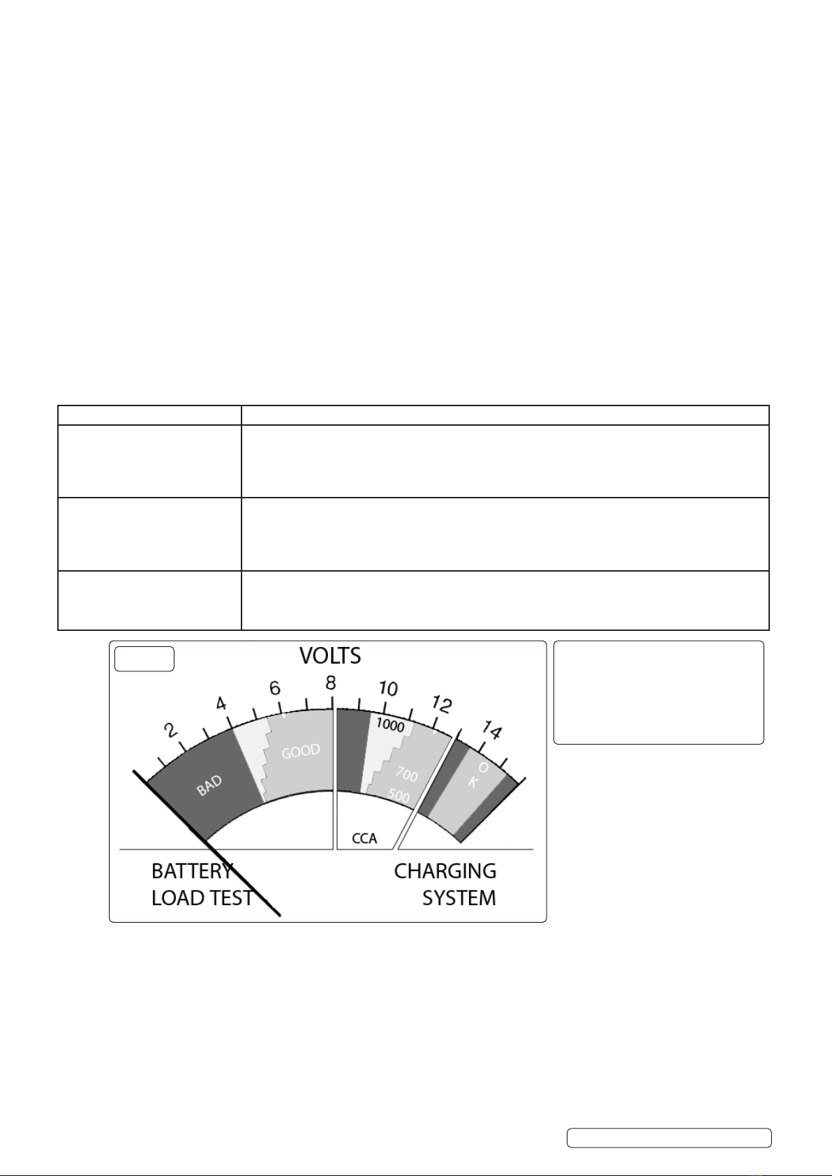
Tests 6 and 12V batteries. Applies load across terminals and reads voltage performance. Also checks charging voltage. Fitted with moving-coil
meter. Features a pistol grip handle for ease of use.
3. OPERATION
WARNING! Ensure you read, understand and apply the safety and operational instructions before connecting the tester clamps to the
battery. Only when you are sure that you understand the procedures is it safe to proceed with the testing process.
BT91/10.V3Issue217/03/21
Original Language Version
© Jack Sealey Limited
Refer to
instructions
Wear eye
protection
Wear protective
gloves
NoopenamesWear protective
clothing
Warning
corrosive
substance
Warning:
explosive
material
Use in well
ventilated areas

3.1. PREPARATION
3.1.1. Check battery casing for cracks or leakage and confirm whether 6 volts or 12 volts.
3.1.2. Clean battery terminals.
3.1.3. If practical, check electrolyte levels and top up with distilled water as required.
3.2. CONNECTION
WARNING! Ensure the vehicle or battery is in a well ventilated area before starting to test.
3.2.1. Attach the positive red clamp to the positive (+) battery terminal. Attach the negative black clamp to the negative (-) battery terminal.
Use the extended clamps if necessary. To ensure good electrical contact twist the clamps on the terminals two or three times. Correct
connection indication will sweep the pointer clockwise across the voltage scale; if connected incorrectly the pointer will sweep
anti clockwise. If there is no movement from the pointer, it is either a bad connection or a dead battery.
3.2.2. Ensure that the clamp cables are clear of hot or moving engine parts, especially if a starter or charging test is required. Ventilation
slots in the tester casing should not be obstructed and the meter scale easily visible with access to the load switch.
3.3. BATTERY LOAD TEST
NOTE! On the first load test, smoke may be emitted from the louvres in the tester casing, this is normal and temporary.
3.3.1. Press the load switch (red rocker switch on the face of the unit beneath the display) and hold until meter reading stabilises, or for a
maximum of 10 seconds. (Failure to release the switch after 10 seconds may result in the switch burning out and your warranty being
invalidated.) Note the meter reading and then release the load switch.
3.3.2. Comparethemeterreadingwithloadtestchart(3.4)todeterminebatterycondition.
NOTES: a) For 12 volt batteries the green sector (fig.1) border is marked with nominal cranking current from 500 to 1000
amps and stepped in 100 amp intervals. Record this figure and compare with battery manufacturer’s quoted figure to give
an indication of any deterioration.
b) Batteryperformancefallsatlowtemperaturesandquotedcrankingampsshouldbereducedby50ampsat20ºF(-7ºC)and
100 amps at 0ºF(-18ºC).
3.4. LOAD TEST CHART
3.5. BATTERY VOLTAGE/CHARGE LEVEL
3.5.1. If the load test result indicates a battery fault allow battery to stabilise for a few minutes and then read the open circuit voltage - meter reading
with load switch ‘Off’.
3.5.2. ComparethereadingwiththeVoltage/Chargetableaboverighttogetanestimationofthechargelevel.
3.5.3. The battery isconsideredchargedat75%ormore.Ifitfailedtheloadtestwith this charge it should be replaced. If the voltage indicates
achargelevelbelow75%thenchargethebatteryandloadtestagain.Ifbatteryfailsthissecondtestreplaceit.
3.6. CHARGING SYSTEM (12 VOLT)
3.6.1. Start engine and allow to reach normal operating temperature. Switch off all accessories.
3.6.2. Run engine at 1200 to 1500rpm and note meter reading, which should be in the green ‘OK’ sector (fig.1). DO NOT press the load switch.
3.6.3. Switch on headlights and heater fan (highest speed), meter reading should remain in the green ‘OK’ sector.
3.6.4. A reading in the red sector to the left (fig.1) indicates a fault in the charging system which will cause the battery to be under charged. A
reading in the red sector to the right (fig.1) indicates a fault which will cause the battery to be over charged.
NOTE: Although not marked on the meter scale the ‘OK’ range for a 6 volt charging system is 6.8 to 7.5 volts.
Load Test Result Battery Condition
OK-Green
12 Volts(g.1-10VGreento13V
Green CCA)
6 Volts(g.1-4VGreento8V
Green)
Batterycapacityisgood.Mayormaynotbefullycharged.Checkelectrolytespecicgravityto
determinechargestate.Ifnotfullycharged,checkforchargingsystemfault(section3.6)orelectrical
drain.
Weak or Bad -yellow or red, but
pointer reading steady.
12 Volts(g.1-8Vto11.4VCCA)
6 Volts(g.1-0Vto5.5V)
Battery capacity is unsatisfactory. Battery may be either:- (1) defective or (2) partly discharged.
Checkelectrolytespecicgravity.Ifover1.225,thebatteryisdefective.Ifunder1.225,rechargethe
batteryandretest.Ifcelltocellspecicgravityvariesbymorethan0.025acelldefectmayexist.If
chargingdoesnotbringspecicgravitytofullchargelevel,thebatteryiseithersulphatedorhaslost
active material.
Weak or Bad - yellow or red, but
pointer reading falling after 10
seconds on load.
Battery may be defective. Release load switch and note the meter reaction. If the voltage recovers to 12
volts (6 volts for a 6 volt battery) or more in a few seconds, then the battery is probably defective. If the
voltagerecoversslowlythebatterymayonlybedischarged.Checktheelectrolytespecicgravityand
proceed as above
Open Circuit Voltage Charge %
12 volt/6 volt battery
11.7/5.8orlower 0
12.0/6.0 25
12.2/6.1 50
12.4/6.2 75
12.6/6.3orhigher 100
g.1
Original Language Version
© Jack Sealey Limited BT91/10.V3Issue217/03/21

3.7. STARTER MOTOR (12 VOLT)
NOTE: Thistestrequiresthatthebatteryisingoodconditionandischargedtoatleast75%capacity.
3.7.1. Disable ignition system (remove fuse or similar) so that engine will not start.
3.7.2. Carryoutaloadtest(section3.3.),ifnotalreadydone,andnotevoltagereading.
3.7.3. Usethetablegivenbelowtodeterminetheequivalentminimumcrankingvoltage.Notethatforenginesoflessthan3.25litrestakethe
next higher figure. For example:
a)3.5litreengine-loadtestresult11.0volts,givesmin.crankingvoltageof9.7volts.
b) 1.5 litre engine - load test result 11.0 volts, gives min. cranking voltage of 10.2 volts
Loadvoltage 10.2 10.4 10.6 10.8 11.0 11.2 11.4
Min.crankingvoltage 7.7 8.2 8.7 9.2 9.7 10.2 10.6
3.7.4. Operate the starter motor and note the voltage during cranking.
3.7.5. A reading below the minimum cranking voltage indicates that the starter motor is taking excessive current. This may be due to poor
connections, to a faulty motor or to the battery being too small for vehicle.
3.7.6. After test reinstate ignition system.
NOTE: For a 6 volt system test as above and note load test voltage. Double this value and determine equivalent min. cranking voltage
asin3.7.3.Halvethefiguretogiveminimumcrankingvoltageforthe6 voltsystemandthenproceedfrom3.7.4.
Sealey Group, Kempson Way, Suffolk Business Park, Bury St Edmunds, Suffolk. IP32 7AR
01284 757500 01284 703534 sales@sealey.co.uk www.sealey.co.uk
ENVIRONMENT PROTECTION
Recycle unwanted materials instead of disposing of them as waste. All tools, accessories and packaging should be sorted, taken to
a recycling centre and disposed of in a manner which is compatible with the environment. When the product becomes completely
unserviceable and requires disposal, drain any fluids (if applicable) into approved containers and dispose of the product and fluids
according to local regulations.
WEEE REGULATIONS
Dispose of this product at the end of its working life in compliance with the EU Directive on Waste Electrical and Electronic Equipment
(WEEE). When the product is no longer required, it must be disposed of in an environmentally protective way. Contact your local solid
waste authority for recycling information.
Note: It is our policy to continually improve products and as such we reserve the right to alter data, specifications and component parts without prior
notice. Please note that other versions of this product are available. If you require documentation for alternative versions, please email or call
ourtechnicalteamontechnical@sealey.co.ukor01284757505.
Important: No Liability is accepted for incorrect use of this product.
Warranty: Guarantee is 12 months from purchase date, proof of which is required for any claim.
Original Language Version
© Jack Sealey Limited BT91/10.V3Issue217/03/21
Table of contents
Other Sealey Test Equipment manuals

Sealey
Sealey BT91/7P User manual

Sealey
Sealey VS926 User manual

Sealey
Sealey V5402.V2 User manual

Sealey
Sealey TA120 User manual

Sealey
Sealey PPHY User manual

Sealey
Sealey TA130.V2 User manual

Sealey
Sealey Auto Service Line TA131 User manual

Sealey
Sealey BT2101 User manual

Sealey
Sealey VS0012 User manual

Sealey
Sealey BT2013.V4 User manual

Sealey
Sealey TST22 User manual

Sealey
Sealey BT2003.V4 User manual

Sealey
Sealey BT2013.V5 User manual

Sealey
Sealey BT2012.V2 User manual

Sealey
Sealey BT2003.V5 User manual

Sealey
Sealey VS925 User manual

Sealey
Sealey PPVT User manual

Sealey
Sealey Auto Service Line VS2030 User manual

Sealey
Sealey CV0011.V2 User manual

Sealey
Sealey VSE211.V4 Firmware update