manuals.online logo
Brands
  1. Home
  2. •
  3. Brands
  4. •
  5. YOKOGAWA
  6. •
  7. Test Equipment
  8. •
  9. YOKOGAWA 3226 User manual

YOKOGAWA 3226 User manual

User's
Manual
Store this manual in an easily accessible
place for quick reference.
General
Model 3226 is a special milliammeter for measuring leakage current of electrical
appliances. The input resistance can be selected from among 1, 1.5 and 2 kΩ
for easy measurement.
Model 3226 is usable for product inspection on production lines and for experimental
measurement in research and design activities. Model 3227 Test Box is available
for the convenience of measurement.
Model 3226 has the following features:
(1) 4-way function: AC current, DC current, DC + AC current and
AC voltage are measurable.
(2) High accuracy: ±2.5% of full scale.
(3) High sensitivity: 0.1 mA for full scale.
(4) TAUT BAND system meter free of friction and strong against vibration and shock.
(5) Overload protective circuit to prevent the meter coil from burning and the meter
pointer from bending
(6) Shielded case to eliminate effect of external high-frequency electric field
(7) Compact and lightweight for easy portable use.
Safety Precautions
When operating the instrument, be sure to observe the cautionary notes given below
to ensure correct and safe use of the instrument. If you use the instrument in any way
other than as instructed in this manual, the instrument’s protective measures may be
impaired. YOKOGAWA is by no means liable for any damage resulting from use of the
instrument in contradiction to these cautionary notes.
The following safety symbols are used on the instrument and
in this manual.
Danger! Handle with Care.
This symbol indicates that the operator must refer to an explanation in the
User’s Manual in order to avoid risk of injury or death of personnel or damage
to the instrument.
WARNING
Indicates a hazard that may result in the loss of life or serious injury of the user
unless the described instruction is abided by.
CAUTION
Indicates a hazard that may result in an injury to the user and/or physical damage to
the product or other equipment unless the described instruction is abided by.
NOTE
Indicates information that is essential for handling the instrument or should be
noted in order to familiarize yourself with the instrument’s operating procedures
and/or functions.
This symbol indicates AC voltage/current.
This symbol indicates a Fuse.
This symbol indicates ground (earth).
T
o avoid injury, death of personnel, carefully observe and follow the warnings
listed below:
WARNING
● Measurement
• Do not operate the instrument over 250 V of high-voltage circuit.
• Do not touch the Input (Output) terminals, when measuring voltage.
● Measuring leads
• Use the leads supplied by Yokogawa for the instrument concerned.
• Do not use a deteriorated or damaged leads.
• Check the leads continuity.
• Do not attach/detach the leads to /from the instrument prior to releasing it
from the measured object.
WARNING
● Protection
• Be sure to use the designated fuse (Rating: voltage, current and type)
to prevent fire
• If there are any cracks or other damage in the case because of being
dropped or struck, the instrument may not be safety insulated.
Do not use the instrument before any remedial measures are taken.
● Replacement of batteries or fuse
• Prior to detaching the cover for replacing the batteries or fuse,
release the lead from the measured object and turn off the switch.
● Operating Environment
• Do not operate the instrument in a flammable or explosive gas atmosphere
• Do not operate the instrument if there is condensation on it.
● Do Not Remove the Case or Disassemble
Do not open the case except when replacing batteries or fuse.
Only Yokogawa service personnel are authorized to remove the casing or
disassemble or modify the instrument.
Do not attempt to repair the instrument yourself, as doing so is extremely
dangerous.
To avoid injury of personnel or damage to the instrument,
carefully observe and follow the cautions listed below:
CAUTION
● Measurement
Do not apply a voltage and current over the allowable limits between the terminals.
● Selector switch
Do not switch the Measuring range selector switch during measurements.
● Batteries
• Do not use different types of batteries together or new and old batteries together.
• If the instrument is not used for a long period, store the instrument with the
batteries removed.
Otherwise, any leakage from the batteries may damage the instrument.
NOTE
Model 3226 has AC + DCmA range. This is used mainly for the instrument which is
operated by DC after rectifying, AC to DC. Therefore, measured value on this range
does not indicate RMS value, but the sum of DC and AC components directly.
1. Block Diagram
Overload
protective
circuit
Battery
check
circuit
Range
selector
circuit
Input
resistance
selector
circuit
Operating
amplifier
Moving-coil
type DC
milliammeter
200 µA F.S.
Internal
resistance: 121 Ω
2. Parts Identification and Functio
BACV
B
0
2
4
6
90
180
120
240
150
300
8
10
AC+DCmA ACmA
DCmA ACV
10
1kΩ
1.5kΩ
2kΩ
INPUT
RESISTANCE
10
10
11
1
0.1 0.1
INPUT
0.1
150
300
BATT
ON
OFF
6. Scale plate
7. Carrying
handle
8. Meter cover
fixing screw
9. Meter cover
10. Measuring
range selector
switch
11. Input
terminals
12. Case
1. B mark
2. Spear
pointer
3. Zero
adjuster
screw
4. Input
resistance
switch
5. Power
on-off/battery
check switch
Fig. 1 Parts Identificatio
1. B mark: The battery is usable if the meter pointer is within
this range when the BATT/ON/OFF switch is
set to the BATT position.
2. Spear pointer
3. Zero adjuster screw: To be turned with a screwdriver for readjusting
zero indication of the pointer.
4. lnput resistance switch: Selects one of the three input resistances
according to the applicable standard.
5. Power on-off/
battery check switch
6. Scale plate: The scale is double graduated in mA and AC V.
7. Carrying handle
8. Meter cover fixing screw
9. Meter cover
10. Measuring range
selector switch:
To be set to an appropriate position according to
the measuring item and range.
11. Input terminals: Accessory H-lead is to be connected to the “INPUT”
terminal, and L-lead to the “ ” (ground) terminal.
12. Case
Model 3226
Universal Leakage Current Tester
IM 3226-E
7th Edition: Oct. 2017 (YMI)
Read this user’s manual before using the instrument in order to fully and correctly
utilize all its functions.
Model: 322610 Universal Leakage Current Tester
322710 Test Box
Contact information of Yokogawa offices worldwide is provided on
the following sheet.
PIM 113-01Z2: Inquiries List of worldwide contacts
A3
Printed inJapan
Test Equipment Depot - 800.517.8431 - 99 Washington Street Melrose, MA 02176 - TestEquipmentDepot.com
3. Operation
3.1 Precautions
1. The most accurate measurement is attained when Model 3226 is placed
horizontally.
2. After placing Model 3226 at the position of use, check that the meter pointer
coincides with the zero point of the scale, if not, adjust it accurately by
turning the zero adjuster screw.
3. When the approximate value of the leakage current to be measured is
unpredictable, measure by first setting the measuring range selector switch to
the 10 mA position.
4. Before measurement, be sure to check that the measuring range selector switch
is in a position proper for the measurement.
Do not operate the switch while the meter pointer is deflecting
5. When storing of carrying Model 3226 after use, set power on-off/battery
check switch.
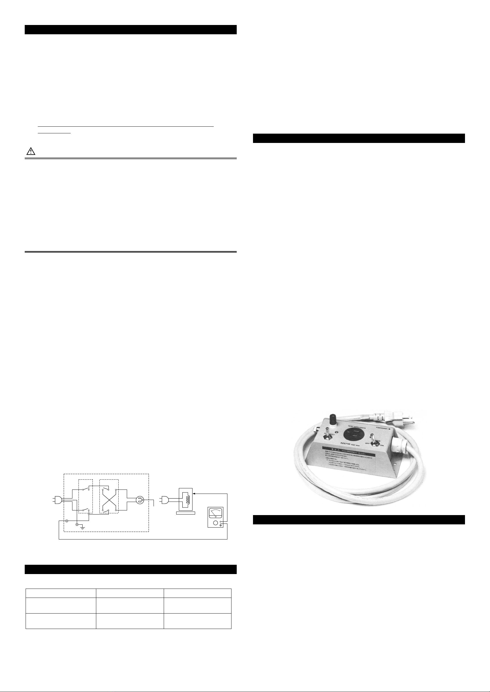
3.2 When using Model 322710 Test Box
WARNING
Before using this instrument, it is necessary to match the polarity with that of
the power plug. Applying 100 V AC to the cabinet of the appliance to be tested
without matching the polarities may cause an electric shock.
● Matching the polarity
Connect the power cord to the power supply.
Turn the power switch to ON and measure the voltage between the earth and
the TEST terminal of this instrument using a Universal leakage voltage tester
(3226 or similar).
If the voltage between the earth and the TEST terminal of this instrument is
• AC30 V or less: the instrument can be used;
• More than AC30 V: use the accessory 3-2 pin adapter and reconnect
the power plug opposite (i.e. turning 180 degrees).
1. Set the power ON–OFF/battery check switch to the “BATT” position and check
the condition of the battery. If the meter pointer is within the battery check-line
range, set the switch to the “ON” position. (If the meter pointer is not within
the battery check-line range, remove the back cover and change the batteries.)
2.
Set the measuring range selector switch to ACV position of Model 3226.
Connect the ground terminal of Model 3226 to the TEST terminal of Model 3227,
then close switch S1
.
3. Connect the “INPUT” terminal (H) of Model 3226 to either of the connector
C1 of Model 3227, and measure the power voltage to check that the voltage is
as rated.
(If the polarity is opposite, the meter pointer will be zero; in this case use switch
S2 to change the polarity.)
4.
Open switch S1, and connect all the simultaneously accessible exposed conductive
surfaces of the to-be-tested appliance together to the “INPUT” terminal (H) of
Model 3226.
5.
Input power plug P2 of the to-be-tested appliance, and turn on all the appliance’s
switches.
6. Leakage current is not necessarily only in the AC spectrum, therefore set
the measuring range selector switch to AC + DC mA range.
7. Close switch S1 of Model 3227, and read the meter of Model 3226.
This reading will tell you the approximate value of the leakage current.
8. Referring to the value obtained in number 7. above, set the range of
the ACmA to the optimum range, and read the meter of Model 3226.
9. Change switch S2 of Model 3227, read the meter of Model 3226, and use
the greater one of the above meter readings as the leakage current value.
10. Set the measuring range selector switch of Model 3226 to the DCmA range,
and read the meter of Model 3226.
11. Repeat the measurement conducted in number 9. above.
12. Start operating the appliance. When the appliance has reached its steady
operating status, measure its leakage current. When not using the Model 3227
Test Box, compose a circuit similar to that shown in Figure 2 and measure.
Model 3227
3226
Power plug
P1
Power plug
P2
Insulation Table
Appliance to be tested
TEST
S1(POWER)
OFF ON ON ON
S2(POLARITY)
connecter
C1
Ground open
Fig. 2 Connection Diagram
4. Calibration
4.1 Instruments necessary for calibration
Instrument Requirements YOKOGAWA equivalent
Standard DC power supply Output: 10 mA
Accuracy: 0.5 % Model 2552
Standard AC power supply Output: 10 mA
Accuracy: 0.5 %
Model 2558
Model 2558A
4.2 Procedure
1 Set the input resistance to 1 kΩ by using the input resistance switch of
Model 3226.
2 Set the power on-off/battery check switch to the “ON’’ position, and adjust
the meter pointer to the zero point of the scale by using the variable resistor
RV2 inside the case.
3 Set the measuring range selector switch to the DC 1 mA position,
supply 1 mA from the standard PC power supply, and adjust the RV1
variable resistor inside the case so that the meter is showing the full scale.
4 Conduct adjustment in the same manner as above, while the measuring
range selector switch is set to DC 10 mA, AC 1 mA and AC 10 mA positions
in sequence. If indication error is large, test and adjust for the most uniform
and highest accuracy of all the measuring ranges.
5 Repeat the foregoing, with the input resistance set to 1.5 and 2 kΩ in sequence.
5. Specification
5.1 Model 322610
Measuring ranges: DC current: 0.1, 1 and 10 mA
AC current: 0.1, 1 and 10 mA
DC+AC current: 0.1, 1 and 10 mA
AC voltage: 150 and 300 V (50 or 60 Hz)
Accuracy: ±2.5% of F.S. (at each range)
Input resistance: Current measuring range: 1, 1.5 and 2 kΩ
Voltage measuring range: Higher than 100 kΩ
Working frequency
range:
20 Hz to 5 kHz
Overload protection: Withstands 30 mA AC
for 1 minute for each current measuring range.
Effect of temperature: Less than ±0.2%/°C with respect to rated value
(within 20 ±10°C)
Insulation resistance: Higher than 100 MΩ at 1000 V DC
between electric circuit and case.
Withstand voltage: 1500 V AC (50 Hz) for 1 minute
between electric circuit and case.
Power source: Two 9 V dry batteries 6F22.
Usable for approx.: 290 hour.
Dimensions Approx. 190×124×90 mm (excluding carrying handle)
Weight: Approx. 1 kg
Accessories: Measuring lead (B9607GT) 1
Carrying bag (B9646BU) 1
User’s manual 1
5.2 Model 322710
Current capacity: 10 AAC (125 V)
Contact resistance: Lower than 0.005 Ω
Insulation resistance: Higher than 100 MΩ at 500 V DC
between electric circuit and case.
Withstand voltage: 1000 V AC for 1 minute
between electric circuit and case.
Dimensions Approx. 70×155×65 mm
Weight: Approx. 0.6 kg
Accessories: 3 to 2 pin adapter
Model 3227 Test Box
6. Maintenance
For accurate measurement at all times, Model 3226 must be kept in the best
condition.
For this purpose, avoid using Model 3226 at a place subject to:
(1) Severe vibration (2) Fill of dust or corrosive gas
(3) Direct sunlight (4) Much moisture
(5) Large variation of ambient temperature (6) Strong external magnetic field
• Both surfaces of the meter cover are coated with anti-static agent.
Do not wipe them hard or clean them with wet cloth,
because such may deteriorate the anti-static effect.
(Use dry, soft cloth, and wipe them lightly with it.)
• The case and meter cover are made of thermoplastic material.
Be careful not to touch them with a soldering iron or other hot object.
Do not clean them with a large quantity of lacquer thinner, benzine or alcohol.
IM 3226-E <P2>

Other YOKOGAWA Test Equipment manuals

YOKOGAWA SL1000 User manual

YOKOGAWA

YOKOGAWA SL1000 User manual

YOKOGAWA CA330 User manual

YOKOGAWA

YOKOGAWA CA330 User manual

YOKOGAWA DL6000 Series User manual

YOKOGAWA

YOKOGAWA DL6000 Series User manual

YOKOGAWA 2560A User manual

YOKOGAWA

YOKOGAWA 2560A User manual

YOKOGAWA CA11E User manual

YOKOGAWA

YOKOGAWA CA11E User manual

YOKOGAWA AQ1100A User manual

YOKOGAWA

YOKOGAWA AQ1100A User manual

YOKOGAWA 702906 User manual

YOKOGAWA

YOKOGAWA 702906 User manual

YOKOGAWA ScopeCorder DL750P User manual

YOKOGAWA

YOKOGAWA ScopeCorder DL750P User manual

YOKOGAWA 2553A User manual

YOKOGAWA

YOKOGAWA 2553A User manual

YOKOGAWA CA71 HANDY CAL User manual

YOKOGAWA

YOKOGAWA CA71 HANDY CAL User manual

YOKOGAWA 279301 User manual

YOKOGAWA

YOKOGAWA 279301 User manual

YOKOGAWA 90020B User manual

YOKOGAWA

YOKOGAWA 90020B User manual

YOKOGAWA MY10 User manual

YOKOGAWA

YOKOGAWA MY10 User manual

YOKOGAWA DL1620 User manual

YOKOGAWA

YOKOGAWA DL1620 User manual

YOKOGAWA DL2700 Series User manual

YOKOGAWA

YOKOGAWA DL2700 Series User manual

YOKOGAWA 701928 User manual

YOKOGAWA

YOKOGAWA 701928 User manual

YOKOGAWA CA320 User manual

YOKOGAWA

YOKOGAWA CA320 User manual

YOKOGAWA CA310 User manual

YOKOGAWA

YOKOGAWA CA310 User manual

YOKOGAWA 701715 User manual

YOKOGAWA

YOKOGAWA 701715 User manual

YOKOGAWA DL9000 Series User manual

YOKOGAWA

YOKOGAWA DL9000 Series User manual

YOKOGAWA CA320 User manual

YOKOGAWA

YOKOGAWA CA320 User manual

YOKOGAWA DLM3022 User manual

YOKOGAWA

YOKOGAWA DLM3022 User manual

YOKOGAWA 30032A User manual

YOKOGAWA

YOKOGAWA 30032A User manual

YOKOGAWA PBL100 User manual

YOKOGAWA

YOKOGAWA PBL100 User manual

Popular Test Equipment manuals by other brands

GoVideo CCTV28 user manual

GoVideo

GoVideo CCTV28 user manual

Check-line FGV-XY operating instructions

Check-line

Check-line FGV-XY operating instructions

ABQINDUSTRIAL Shimpo DT-315AEB manual

ABQINDUSTRIAL

ABQINDUSTRIAL Shimpo DT-315AEB manual

Digi-Sense 20250-24 user manual

Digi-Sense

Digi-Sense 20250-24 user manual

Delta MS-ACT50-4K user manual

Delta

Delta MS-ACT50-4K user manual

Metrix MX 535 user manual

Metrix

Metrix MX 535 user manual

Digi-Shot plus.4G manual

Digi-Shot

Digi-Shot plus.4G manual

ACS ALERT J4X quick guide

ACS

ACS ALERT J4X quick guide

Kikusui OT03-PCR-WEA user manual

Kikusui

Kikusui OT03-PCR-WEA user manual

Major tech MT474 instruction manual

Major tech

Major tech MT474 instruction manual

Compliance West MegaPulse Defib-5PF-002 instruction manual

Compliance West

Compliance West MegaPulse Defib-5PF-002 instruction manual

Teradyne Z1800 Series Site preparation guide

Teradyne

Teradyne Z1800 Series Site preparation guide

Weishi 1000 user manual

Weishi

Weishi 1000 user manual

Buckleys ST-AC Pro operating instructions

Buckleys

Buckleys ST-AC Pro operating instructions

Altek Pocketcal 134-2 operating instructions

Altek

Altek Pocketcal 134-2 operating instructions

PANCONTROL PAN Volttester 400 manual

PANCONTROL

PANCONTROL PAN Volttester 400 manual

ring RBA15 instructions

ring

ring RBA15 instructions

JYE Tech 062 How to use

JYE Tech

JYE Tech 062 How to use

manuals.online logo
manuals.online logoBrands
  • About & Mission
  • Contact us
  • Privacy Policy
  • Terms and Conditions

Copyright 2025 Manuals.Online. All Rights Reserved.