manuals.online logo
Brands
  1. Home
  2. •
  3. Brands
  4. •
  5. ECS Electronics
  6. •
  7. Automobile Accessories
  8. •
  9. ECS Electronics VA-010-13MU User manual

ECS Electronics VA-010-13MU User manual

1/21
This electric kit has to be installed by a professional workshop or a suitable qualified person.
The installation instructions must have been read and fully understood before the start of any installation. Please contact your wiring kit provider or the hotline shown in the footer
should you need assistance!
Make sure the vehicle is approved/homologated by the manufacturer to tow a trailer!
Also please check that there is a definite compatibility between this vehicle and the electric kit!
Following the installation of the electric kit, the fitting instructions should be kept together with the vehicle service document and vehicle handbook. The fitting instructions contain
important information relating to the use and function of the towing kit as well as for any diagnostic or activation process, that might have to be repeated in the future (e.g. after the
performance of a vehicle software update).
All warranty claims will be forfeited if the electric kit or components contained therein are used incorrectly or modified. If a towing socket adaptor has been used to connect to the
trailer or bike rack, this must be removed from the trailer socket once the trailer or bike rack has been disconnected.
If the trailer or bike rack is not equipped with a rear fog lamp, depending on the towing vehicle type, the correct function of the towing kit cannot be guaranteed. In such cases, a rear
fog lamp should be retro fitted.
This towing electric kit will not be covered under warranty if any technical or electrical modifications or software updates have been performed by the vehicle manufacturer after the
initial commissioning of the kit. That applies especially to modifications or updates which may cause malfunctions in the trailer socket or any other part of the trailer electrical
equipment!
Depending on the type of trailer module used in this electric kit, diagnostic interrogation with the vehicle’s electrical system may be limited or will not function. The error memory
inside the trailer module may not be able to be accessed by vehicle manufacturers diagnostic system.
Error logs relating to the trailer electrical equipment, that may be generated in the vehicle manufacturers diagnostic system as a result of a test procedure, may be due to the
incorrect installation of the towing electric kit or the false activation of the trailer module.
We always recommend whenever possible, the following troubleshooting process:
An analysis of the vehicle’s error memory and possibly clearing of all faults before the start of the installation!
Try disconnecting the trailer module from the towing harness and re-start the fault clearing process!
If in doubt, limit the time for troubleshooting to a max of 0,5 hours and call our Technical Support Team!
Please follow our instructions carefully and always test the towing electrics using a true lighting board or a specifically designed bulb tester. If an LED tester is used, ensure it is
equipped with correct load resistors or malfunctions will occur!
This instruction is subject to changes and we reserve the right to make changes to design, colour etc.
All of the data and illustrations may not be an exact representation but the text contained in this instruction must be observed!
Part No: VA-010-13MU
Citroen C4
Citroen ë-C4
Vauxhall Mokka (B)
Vauxhall Mokka-e
01/2021 >>
01/2021 >>
03/2021 >>
03/2021 >>
Revision: 3 / 26.12.2022
VA-010-13MU
ECS UK
c/o 3 Hardman Street
Manchester
M3 3AT
Email-sales: [email protected]
Email-technical: [email protected]
SALE: +44 (0) 7980 847124
TECHNICAL: +44 (0) 7590 564639
WEB: www.ecs-electronicsuk.co.uk
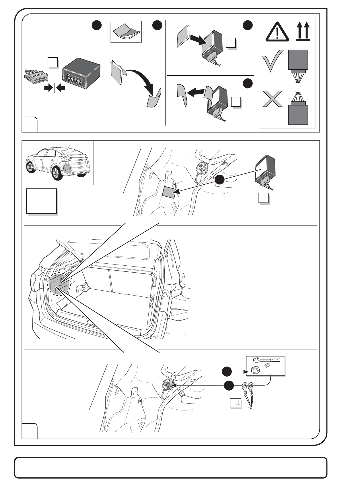
Set up trailer operation
!
The light functions on the
trailer will only operate
AFTER the vehicle has
been re-coded!
Electric wiring kit for towbars / 13-pin / 12 Volt / ISO 11446
[email protected]
www.ecs-electronicsuk.co.uk
2/21
4-11
M
16-35
12-14
5x
M
X
G
U1
L1
*Optional
Page 18
3x
3x 3x 1x
C
1x
20 Amp.
20 Amp.
1x
1x10x
20 Amp.
mini fuse
20 Amp.
1x
U2
U3 U4U5
Revision: 3 / 26.12.2022
VA-010-13MU
ECS UK
c/o 3 Hardman Street
Manchester
M3 3AT
Email-sales: [email protected]
Email-technical: [email protected]
SALE: +44 (0) 7980 847124
TECHNICAL: +44 (0) 7590 564639
WEB: www.ecs-electronicsuk.co.uk
Part No: **-***-***
*/**
Electric wiring kit for towbars / **-pin / 12 Volt / ISO *****
Thiselectric kit has to be installed by a professional workshop or a suitable qualified person.
Theinstallation instructions must have been read and fully understood before the start of any installation. Please contact your wiring kit provider or the hotline shown in the footer
shouldyou need assistance!
Makesure the vehicle is approved/homologated by the manufacturer to tow a trailer!
Alsoplease check that there is a definite compatibility between this vehicle and the electric kit!
Followingthe installation of the electric kit, the fitting instructions should be kept together with the vehicle service document and vehicle handbook. The fitting instructions contain
importantinformation relating to the use and function of the towing kit as well as for any diagnostic or activation process, that might have to be repeated in the future (e.g.after the
performanceof a vehicle software update).
Allwarranty claims will be forfeited if the electric kit or components contained therein are used incorrectly or modified. If a towing socket adaptor has been used to connect to the
traileror bike rack, this must be removed from the trailer socket once the trailer or bikerack has been disconnected.
Ifthe trailer or bike rack is not equipped with a rear fog lamp, depending on the towing vehicle type, the correct function of the towingkit cannot be guaranteed. In such cases, a rear
foglamp should be retro fitted.
Thistowing electric kit will not be covered under warranty if any technical or electrical modifications or software updates have been performed by the vehicle manufacturerafter the
initialcommissioning of the kit. That applies especially to modifications or updates which may cause malfunctions in the trailer socketor any other par t of the trailer electrical
equipment!
Dependingon the type of trailer module used in this electric kit, diagnostic interrogation with the vehicle’s electrical system may be limited or will not function.The error memor y
insidethe trailer module may not be able to be accessed by vehicle manufacturers diagnostic system.
Errorlogs relating to the trailer electrical equipment, that may be generated in the vehicle manufacturers diagnostic system as a result of a test procedure, may be due to the
incorrectinstallation of the towing electric kit or the false activation of the trailer module.
Wealways recommend whenever possible, the following troubleshootingprocess:
Ananalysis of the vehicle’s error memory and possibly clearing of all faults before the start of the installation!
Trydisconnecting the trailer module from the towing harness and re-start the fault clearing process!
Ifin doubt, limit the time for troubleshooting to a max of 0,5 hours and call our TechnicalSupport Team!
Pleasefollow our instructions carefully and always test the towing electrics using a true lighting board or a specifically designed bulb tester.If an LED tester is used, ensure it is
equippedwith correct load resistors or malfunctions will occur!
Thisinstruction is subject to changes and we reserve the right to make changes to design, colour etc.
Allof the data and illustrations may not be an exact representation but the text contained in this instruction must be observed!
******** **/**** >>
************
[email protected]
www.ecs-electronicsuk.co.uk
Revision:* / **.**.****
**-***-***
ECSUK
c/o3 Hardman Street
Manchester
M33AT
Email-sales:[email protected]
Email-technical:[email protected]
SALE: +44(0) 7980 847124
TECHNICAL: +44(0) 7590 564639
WEB:www.ecs-electronicsuk.co.uk
3/21
SYMBOL EXPLANATION
TOOLS
Left (58-L) respectively
Right (58-R) tail light
Stop light (54) /
high mounted, third stop light (54)
Turn signal indicator left
Turn signal indicator right
Rear fog light(s)
Reversing light(s)
Trailer / trailer recognition
Permanent current power supply
Ground or Earth (31)
Ground connection battery terminal lug
Permanent power supply /
13pin socket, chamber 9
Charging wire for trailer battery /
13pin socket, chamber 10
+
15+
+
30+
Positive connection battery terminal lug
54 STOP
L
R
Reverse
B+/30
Fuse / fuse capacity 20 Ampère
Cigarette lighter /
accessory socket
Loudspeaker / buzzer
Park Distance Control
Switch / source of function
Connect together
Disconnect
Look at / See further information
Look carefully at selected area
Present / Occupied / OK
Not present / Not occupied / Not OK
Acoustic indication
Attention / important advice
20 Amp.
20 Amp.
12V
1
ATTENTION!
ATTENTION! In order to avoid mal-functionsand damage to the vehicle’s electrical system the earth terminal must be
disconnected from the vehicle’s battery before starting work!
Both the trailer module and the vehicle’s control unit for the electrical system can be damaged during work
on the data bus connections if the battery is not disconnected!
Please pay attention to the manufacturer’s instructions whendisconnecting and reconnecting the vehicle’s battery!
The vehicle's cooling capacity mayhave to be increased when retrofitting a trailer coupling!
You must observe the manufacturer's instructions!!
!Code
3:3
Note: It may be necessary
to check if this vehicle has
a stored radio code before
disconnecting the battery!
Co
Co
Co
Co
Revision: 3 / 26.12.2022
VA-010-13MU
ECS UK
c/o 3 Hardman Street
Manchester
M3 3AT
Email-sales: [email protected]
Email-technical: [email protected]
SALE: +44 (0) 7980 847124
TECHNICAL: +44 (0) 7590 564639
WEB: www.ecs-electronicsuk.co.uk
4/21
Code vehicle for lighting functions
2
3
1
2
3
4
5
6
C4
ё-C4
Revision: 3 / 26.12.2022
VA-010-13MU
ECS UK
c/o 3 Hardman Street
Manchester
M3 3AT
Email-sales: [email protected]
Email-technical: [email protected]
SALE: +44 (0) 7980 847124
TECHNICAL: +44 (0) 7590 564639
WEB: www.ecs-electronicsuk.co.uk
Vauxhall
CODING
DIAGBOX
5/21
4
5
SEAL WITH
SILICONE.
X
1
2
3
4
5
6
C4
ё-C4
Mokka
Mokka-e
1
2
3
4
5
Revision: 3 / 26.12.2022
VA-010-13MU
ECS UK
c/o 3 Hardman Street
Manchester
M3 3AT
Email-sales: [email protected]
Email-technical: [email protected]
SALE: +44 (0) 7980 847124
TECHNICAL: +44 (0) 7590 564639
WEB: www.ecs-electronicsuk.co.uk
6/21
6
SEAL WITH
SILICONE.
X
1
2
3
4
5
6
Mokka
Mokka-e
Revision: 3 / 26.12.2022
VA-010-13MU
ECS UK
c/o 3 Hardman Street
Manchester
M3 3AT
Email-sales: [email protected]
Email-technical: [email protected]
SALE: +44 (0) 7980 847124
TECHNICAL: +44 (0) 7590 564639
WEB: www.ecs-electronicsuk.co.uk
7/21
7
11
Option 1 Option 2
XX
Page 21
SOCKET CONNECTION
8
9
Option 3 1 2 3
10
1 2 3
Option 2
Option 1
X
Revision: 3 / 26.12.2022
VA-010-13MU
ECS UK
c/o 3 Hardman Street
Manchester
M3 3AT
Email-sales: [email protected]
Email-technical: [email protected]
SALE: +44 (0) 7980 847124
TECHNICAL: +44 (0) 7590 564639
WEB: www.ecs-electronicsuk.co.uk
8/21
12
13
M
M
M
1 2 3
4
M
10 mm
G
2
3
1
C4
ё-C4
Revision: 3 / 26.12.2022
VA-010-13MU
ECS UK
c/o 3 Hardman Street
Manchester
M3 3AT
Email-sales: [email protected]
Email-technical: [email protected]
SALE: +44 (0) 7980 847124
TECHNICAL: +44 (0) 7590 564639
WEB: www.ecs-electronicsuk.co.uk
9/21
14
15
M
1
10 mm
G
2
3
Mokka
Mokka-e
Revision: 3 / 26.12.2022
VA-010-13MU
ECS UK
c/o 3 Hardman Street
Manchester
M3 3AT
Email-sales: [email protected]
Email-technical: [email protected]
SALE: +44 (0) 7980 847124
TECHNICAL: +44 (0) 7590 564639
WEB: www.ecs-electronicsuk.co.uk
10/21
16
18
1
2
17 3x
2x
DISCONNECT LIGHT
1
2
3
2x
Revision: 3 / 26.12.2022
VA-010-13MU
ECS UK
c/o 3 Hardman Street
Manchester
M3 3AT
Email-sales: [email protected]
Email-technical: [email protected]
SALE: +44 (0) 7980 847124
TECHNICAL: +44 (0) 7590 564639
WEB: www.ecs-electronicsuk.co.uk
11/21
19
20
1x
Revision: 3 / 26.12.2022
VA-010-13MU
ECS UK
c/o 3 Hardman Street
Manchester
M3 3AT
Email-sales: [email protected]
Email-technical: [email protected]
SALE: +44 (0) 7980 847124
TECHNICAL: +44 (0) 7590 564639
WEB: www.ecs-electronicsuk.co.uk
12/21
21
22
Yellow
60-Pin
L
1
2
Revision: 3 / 26.12.2022
VA-010-13MU
ECS UK
c/o 3 Hardman Street
Manchester
M3 3AT
Email-sales: [email protected]
Email-technical: [email protected]
SALE: +44 (0) 7980 847124
TECHNICAL: +44 (0) 7590 564639
WEB: www.ecs-electronicsuk.co.uk
13/21
Revision: 3 / 26.12.2022
VA-010-13MU
ECS UK
c/o 3 Hardman Street
Manchester
M3 3AT
Email-sales: [email protected]
Email-technical: [email protected]
SALE: +44 (0) 7980 847124
TECHNICAL: +44 (0) 7590 564639
WEB: www.ecs-electronicsuk.co.uk
24
23
L
L
1
2
24
32
28
44
29 44
Option 1 Option 2
-
-
-
1
REUSEABLE
2
3
L
Open Lock!
Brown
L1
C
Option 1
14/21
Revision: 3 / 26.12.2022
VA-010-13MU
ECS UK
c/o 3 Hardman Street
Manchester
M3 3AT
Email-sales: [email protected]
Email-technical: [email protected]
SALE: +44 (0) 7980 847124
TECHNICAL: +44 (0) 7590 564639
WEB: www.ecs-electronicsuk.co.uk
27
25
26
Option 1
Option 1
Option 1
L1
PIN 49
PIN 47
PIN 52
Black
Blue/Red
Yellow
Pin 47
Pin 49
Pin 52
Black
Yellow
Blue/Red
Brown
L1
If postitions 47/49/52 are occupied
Brown
L1
Remove wires from positions 47/49/52 and isolate them
PIN 49
PIN 47
PIN 52
1
2
3x
L1
Brown
15/21
28
30
C
C
L
Option 1
L1
Brown
L
29
L1
PIN 49
PIN 47
PIN 52
Black
Blue/Red
Brown
Yellow
Pin 47
Pin 49
Pin 52
Black
Yellow
Blue/Red
Option 2
Option 2
Brown
Revision: 3 / 26.12.2022
VA-010-13MU
ECS UK
c/o 3 Hardman Street
Manchester
M3 3AT
Email-sales: [email protected]
Email-technical: [email protected]
SALE: +44 (0) 7980 847124
TECHNICAL: +44 (0) 7590 564639
WEB: www.ecs-electronicsuk.co.uk
16/21
31
33
32
Option 2
L
Brown
C
1x
L
Yellow
60-Pin
L
3
1
2
U1
U2
U3
C4
ё-C4
Mokka
Mokka-e
U4
U5
REUSEABLE
REUSEABLE
20 Amp.
20 Amp.
Revision: 3 / 26.12.2022
VA-010-13MU
ECS UK
c/o 3 Hardman Street
Manchester
M3 3AT
Email-sales: [email protected]
Email-technical: [email protected]
SALE: +44 (0) 7980 847124
TECHNICAL: +44 (0) 7590 564639
WEB: www.ecs-electronicsuk.co.uk
20 Amp.
20 Amp.
2
20 Amp.
20 Amp.
B+/30 U3
17/21
34
35
!
Important!
Please do not mount
the fuse tap and its
wiring output in
the other
direction!
F10
F11
1
Pos. F10
3
F10
F11
C4
ё-C4
!
Important!
Please do not mount
the fuse tap and its
wiring output in
the other
direction!
Mokka
Mokka-e
B+/30
1
2
Pos. F28
3
5 Amp.
20 Amp.
U3
5 Amp.
20 Amp.
Revision: 3 / 26.12.2022
VA-010-13MU
ECS UK
c/o 3 Hardman Street
Manchester
M3 3AT
Email-sales: [email protected]
Email-technical: [email protected]
SALE: +44 (0) 7980 847124
TECHNICAL: +44 (0) 7590 564639
WEB: www.ecs-electronicsuk.co.uk
18/21
Revision: 3 / 26.12.2022
VA-010-13MU
ECS UK
c/o 3 Hardman Street
Manchester
M3 3AT
Email-sales: [email protected]
Email-technical: [email protected]
SALE: +44 (0) 7980 847124
TECHNICAL: +44 (0) 7590 564639
WEB: www.ecs-electronicsuk.co.uk
36
38
!Code
3:3
37
The activation of the trailer functions
has to be carried out using the
CITROËN DIAGBOX as follows:
• choose vehicle
• delivery
• equipment
• trailer control unit (BSR)
• installation of equipment
Optional
+
+-
15 amp.
15+
PIN 10
PIN 9
+-
15 amp.
+30
Extension kits
SP-133-ZZ or SP-448-ZZU
Consult your supplier!
CITROEN
C4
ё-C4
Mokka
Mokka-e
VAUXHALL
Vauxhall
CODING
DIAGBOX
19/21
Revision: 3 / 26.12.2022
VA-010-13MU
ECS UK
c/o 3 Hardman Street
Manchester
M3 3AT
Email-sales: [email protected]
Email-technical: [email protected]
SALE: +44 (0) 7980 847124
TECHNICAL: +44 (0) 7590 564639
WEB: www.ecs-electronicsuk.co.uk
39
41
40
L54 STOP
R
Reverse
WARNING
OFF
V
Hz
Hz
Hz
Hz
A
V
COM
10A
400
mA
mA
V
mV
HOLD MINMAX RANGE
DC
Manual Range 60
+
V
Functional test
!
L R
L R
MENU
OK
P500 miles
6666 miles
Driving Aids
6:00 AM 36 F
C H
0
1
2
345
6
7
8
RPMx1000
1/2 10
20
40
60 80
100
120
140
160
20
40
60
80
100 120 140 160
180
200
220
240
260
km/h
LED
part no.
LIGHTMATEII
LIGHTMATEIII
20/21
Revision: 3 / 26.12.2022
VA-010-13MU
ECS UK
c/o 3 Hardman Street
Manchester
M3 3AT
Email-sales: [email protected]
Email-technical: [email protected]
SALE: +44 (0) 7980 847124
TECHNICAL: +44 (0) 7590 564639
WEB: www.ecs-electronicsuk.co.uk
42
44
43
Part No: **-***-***
*/**
Electric wiring kit for towbars / **-pin / 12 Volt / ISO *****
Thiselectric kit has to be installed by a professional workshop or a suitable qualified person.
Theinstallation instructions must have been read and fully understood before the start of any installation. Please contact your wiring kit provider or the hotline shown in the footer
shouldyou need assistance!
Makesure the vehicle is approved/homologated by the manufacturer to tow a trailer!
Alsoplease check that there is a definite compatibility between this vehicle and the electric kit!
Followingthe installation of the electric kit, the fitting instructions should be kept together with the vehicle service document and vehicle handbook. The fitting instructions contain
importantinformation relating to the use and function of the towing kit as well as for any diagnostic or activation process, that might have to be repeated in the future (e.g.after the
performanceof a vehicle software update).
Allwarranty claims will be forfeited if the electric kit or components contained therein are used incorrectly or modified. If a towing socket adaptor has been used to connect to the
traileror bike rack, this must be removed from the trailer socket once the trailer or bikerack has been disconnected.
Ifthe trailer or bike rack is not equipped with a rear fog lamp, depending on the towing vehicle type, the correct function of the towingkit cannot be guaranteed. In such cases, a rear
foglamp should be retro fitted.
Thistowing electric kit will not be covered under warranty if any technical or electrical modifications or software updates have been performed by the vehicle manufacturerafter the
initialcommissioning of the kit. That applies especially to modifications or updates which may cause malfunctions in the trailer socketor any other par t of the trailer electrical
equipment!
Dependingon the type of trailer module used in this electric kit, diagnostic interrogation with the vehicle’s electrical system may be limited or will not function.The error memor y
insidethe trailer module may not be able to be accessed by vehicle manufacturers diagnostic system.
Errorlogs relating to the trailer electrical equipment, that may be generated in the vehicle manufacturers diagnostic system as a result of a test procedure, may be due to the
incorrectinstallation of the towing electric kit or the false activation of the trailer module.
Wealways recommend whenever possible, the following troubleshootingprocess:
Ananalysis of the vehicle’s error memory and possibly clearing of all faults before the start of the installation!
Trydisconnecting the trailer module from the towing harness and re-start the fault clearing process!
Ifin doubt, limit the time for troubleshooting to a max of 0,5 hours and call our TechnicalSupport Team!
Pleasefollow our instructions carefully and always test the towing electrics using a true lighting board or a specifically designed bulb tester.If an LED tester is used, ensure it is
equippedwith correct load resistors or malfunctions will occur!
Thisinstruction is subject to changes and we reserve the right to make changes to design, colour etc.
Allof the data and illustrations may not be an exact representation but the text contained in this instruction must be observed!
******** **/**** >>
************
[email protected]
www.ecs-electronicsuk.co.uk
Revision:* / **.**.****
**-***-***
ECSUK
c/o3 Hardman Street
Manchester
M33AT
Email-sales:[email protected]
Email-technical:[email protected]
SALE: +44(0) 7980 847124
TECHNICAL: +44(0) 7590 564639
WEB:www.ecs-electronicsuk.co.uk
13-pin 7-pin
Adapter socket
Optional

Other ECS Electronics Automobile Accessories manuals

ECS Electronics FR-077-D1U User manual

ECS Electronics

ECS Electronics FR-077-D1U User manual

ECS Electronics TO-245-BHU User manual

ECS Electronics

ECS Electronics TO-245-BHU User manual

ECS Electronics IV-005-BLU User manual

ECS Electronics

ECS Electronics IV-005-BLU User manual

ECS Electronics HY-046-DG User manual

ECS Electronics

ECS Electronics HY-046-DG User manual

ECS Electronics CT-050-B1 User manual

ECS Electronics

ECS Electronics CT-050-B1 User manual

ECS Electronics HY-070-BH User manual

ECS Electronics

ECS Electronics HY-070-BH User manual

ECS Electronics RN-071-BL User manual

ECS Electronics

ECS Electronics RN-071-BL User manual

ECS Electronics CH-011-BB User manual

ECS Electronics

ECS Electronics CH-011-BB User manual

ECS Electronics OP-008-BB User manual

ECS Electronics

ECS Electronics OP-008-BB User manual

ECS Electronics DA-005-BB User manual

ECS Electronics

ECS Electronics DA-005-BB User manual

ECS Electronics PE-059-D1U User manual

ECS Electronics

ECS Electronics PE-059-D1U User manual

ECS Electronics TO-139-DB User manual

ECS Electronics

ECS Electronics TO-139-DB User manual

ECS Electronics TO-245-HHU User manual

ECS Electronics

ECS Electronics TO-245-HHU User manual

ECS Electronics KI-099-BL User manual

ECS Electronics

ECS Electronics KI-099-BL User manual

ECS Electronics HY-123-DX User manual

ECS Electronics

ECS Electronics HY-123-DX User manual

ECS Electronics OP-052-D1 User manual

ECS Electronics

ECS Electronics OP-052-D1 User manual

ECS Electronics KI-132-DX User manual

ECS Electronics

ECS Electronics KI-132-DX User manual

ECS Electronics CR-066-BHU User manual

ECS Electronics

ECS Electronics CR-066-BHU User manual

ECS Electronics SUZ-019-B User manual

ECS Electronics

ECS Electronics SUZ-019-B User manual

ECS Electronics OP-052-D1U User manual

ECS Electronics

ECS Electronics OP-052-D1U User manual

ECS Electronics VL-001-BQ User manual

ECS Electronics

ECS Electronics VL-001-BQ User manual

ECS Electronics TO-295-07U User manual

ECS Electronics

ECS Electronics TO-295-07U User manual

ECS Electronics HY-050-DH User manual

ECS Electronics

ECS Electronics HY-050-DH User manual

ECS Electronics CT-052-D1 User manual

ECS Electronics

ECS Electronics CT-052-D1 User manual

Popular Automobile Accessories manuals by other brands

Delta EV Ultra installation manual

Delta

Delta EV Ultra installation manual

Air Lift LoadLifter 5000 Ultimate installation guide

Air Lift

Air Lift LoadLifter 5000 Ultimate installation guide

TREX ZROADZ Series installation guide

TREX

TREX ZROADZ Series installation guide

Pet Gear supertraX PG9371GRSX instruction manual

Pet Gear

Pet Gear supertraX PG9371GRSX instruction manual

ICON 97721EP installation instructions

ICON

ICON 97721EP installation instructions

Purpleline fullstop GEMINI Installation guide and user's manual

Purpleline

Purpleline fullstop GEMINI Installation guide and user's manual

Dirtydog 4x4 DD-P-JK4-07 installation instructions

Dirtydog 4x4

Dirtydog 4x4 DD-P-JK4-07 installation instructions

FormFit HDW 20G 03 manual

FormFit

FormFit HDW 20G 03 manual

Silvercrest SBTF 10 C2 operating instructions

Silvercrest

Silvercrest SBTF 10 C2 operating instructions

Air Lift loadlifter 5000 installation guide

Air Lift

Air Lift loadlifter 5000 installation guide

FormFit HD 1D 03 installation instructions

FormFit

FormFit HD 1D 03 installation instructions

PowerAcoustik METER 4 Installation

PowerAcoustik

PowerAcoustik METER 4 Installation

Steelcraft HEAVY DUTY BULL NOSE FRONT BUMPER quick start guide

Steelcraft

Steelcraft HEAVY DUTY BULL NOSE FRONT BUMPER quick start guide

Jin-Wei WD-4KS user manual

Jin-Wei

Jin-Wei WD-4KS user manual

Pro-gard Products LLC. B5802EXPD18 installation guide

Pro-gard Products LLC.

Pro-gard Products LLC. B5802EXPD18 installation guide

Air Lift AutoPilot V2 installation guide

Air Lift

Air Lift AutoPilot V2 installation guide

Power Fist CLASS II quick start guide

Power Fist

Power Fist CLASS II quick start guide

NAV TOOL NAVRGB6.0-VI installation manual

NAV TOOL

NAV TOOL NAVRGB6.0-VI installation manual

manuals.online logo
manuals.online logoBrands
  • About & Mission
  • Contact us
  • Privacy Policy
  • Terms and Conditions

Copyright 2025 Manuals.Online. All Rights Reserved.