ECS 945GCT-D User manual


Preface
Preface
Copyright
This publication, including all photographs, illustrations and software, is protected
under international copyright laws, with all rights reserved. Neither this manual, nor
any of the material contained herein, may be reproduced without written consent of
the author.
Version 1.0
Disclaimer
The information in this document is subject to change without notice. The manufac-
turer makes no representations or warranties with respect to the contents hereof and
specifically disclaims any implied warranties of merchantability or fitness for any
particular purpose. The manufacturer reserves the right to revise this publication and
to make changes from time to time in the content hereof without obligation of the
manufacturer to notify any person of such revision or changes.
TrademarkRecognition
Microsoft, MS-DOS and Windows are registered trademarks of Microsoft Corp.
MMX, Pentium, Pentium-II, Pentium-III, Celeron are registered trademarks of Intel
Corporation.
Other product names used in this manual are the properties of their respective
owners and are acknowledged.
FederalCommunicationsCommission(FCC)
This equipment has been tested and found to comply with the limits for a Class B
digital device, pursuant to Part 15 of the FCC Rules. These limits are designed to
provide reasonable protection against harmful interference in a residential installa-
tion. This equipment generates, uses, and can radiate radio frequency energy and, if
not installed and used in accordance with the instructions, may cause harmful inter-
ference to radio communications. However, there is no guarantee that interference
will not occur in a particular installation. If this equipment does cause harmful
interference to radio or television reception, which can be determined by turning the
equipment off and on, the user is encouraged to try to correct the interference by one
or more of the following measures:
• Reorient or relocate the receiving antenna
• Increase the separation between the equipment and the receiver
• Connect the equipment onto an outlet on a circuit different from that to
which the receiver is connected
• Consult the dealer or an experienced radio/TV technician for help
Shielded interconnect cables and a shielded AC power cable must be employed with
this equipment to ensure compliance with the pertinent RF emission limits govern-
ing this device. Changes or modifications not expressly approved by the system’s
manufacturer could void the user’s authority to operate the equipment.

ii
Preface
DeclarationofConformity
This device complies with part 15 of the FCC rules. Operation is subject to the
following conditions:
• This device may not cause harmful interference, and
• This device must accept any interference received, including interfer-
ence that may cause undesired operation
CanadianDepartmentofCommunications
This class B digital apparatus meets all requirements of the Canadian Interference-
causing Equipment Regulations.
Cet appareil numérique de la classe B respecte toutes les exigences du Réglement sur
le matériel brouilieur du Canada.
AbouttheManual
The manual consists of the following:
Chapter 1
Introducing the Motherboard
Chapter 2
Installing the Motherboard
Chapter 3
UsingBIOS
Chapter 4
Using the Motherboard Software
Describes features of the
motherboard.
Go to Hpage 1
Describes installation of
motherboard components.
Goto Hpage 7
Provides information on us-
ing the BIOS Setup Utility.
Go to Hpage 23
Describes the motherboard
software
Go to Hpage 37

iii
TT
TT
TABLE OF CONTENTSABLE OF CONTENTS
ABLE OF CONTENTSABLE OF CONTENTS
ABLE OF CONTENTS
Preface i
Chapter 1 1
IntroducingtheMotherboard 1
Introduction......................................................................................1
Feature...............................................................................................2
MotherboardComponents.............................................................4
Chapter 2 77
77
7
Installing the Motherboard 7
SafetyPrecautions...........................................................................7
Choosinga ComputerCase............................................................7
Installingthe Motherboard inaCase............................................7
CheckingJumperSettings...............................................................8
Setting Jumpers...................................................................8
Checking Jumper Settings...................................................9
Jumper Settings...................................................................9
ConnectingCase Components.....................................................10
Front Panel Header...........................................................12
Installing Memory Modules...............................................13
Installinga Hard Disk Drive/CD-ROM/SATAHardDrive...16
Installing Add-on Cards....................................................18
Connecting Optional Devices............................................20
ConnectingI/ODevices................................................................22
Chapter 3 23
UsingBIOS 23
Aboutthe SetupUtility................................................................23
The Standard Configuration..............................................23
Entering the Setup Utility...................................................23
Updating the BIOS............................................................25
UsingBIOS......................................................................................25
Standard CMOS Setup......................................................26
Advanced Setup.................................................................28
Advanced Chipset Setup....................................................29

iv
Integrated Peripherals.......................................................30
Power Management Setup.................................................31
PCI/PnP Setup...................................................................32
PC Health Status...............................................................33
Frequency/Voltage Control................................................34
Load Default Settings........................................................35
Supervisor Password........................................................35
User Password..................................................................36
Save & Exit Setup..............................................................36
Exit Without Saving............................................................36
Chapter 4 3737
3737
37
UsingtheMotherboardSoftware 37
Aboutthe SoftwareCD-ROM......................................................37
Auto-installingunderWindows2000/XP/Vista.........................37
Running Setup....................................................................38
ManualInstallation........................................................................42
UtilitySoftwareReference............................................................42

1
IntroducingtheMotherboard
Chapter1
IntroducingtheMotherboard
Introduction
Thank you for choosing 945GCT-D motherboard of great performance and with
enhanced function. This motherboard has onboard Intel Diamondville CPU with a
Micro DTX form factor of 200 x 170 mm.
The motherboard incorporates the 945GC Northbridge (NB) and ICH7 Southbridge
(SB) chipsets. The Northbridge supports a Front Side Bus (FSB) frequency of 533
MHz using a scalable FSB Vcc_CPU. The memory controller supports DDR2 memory
DIMM frequencies of 533/400. It supports two DDR2 Sockets with up to maximum
memory of 2GB.
The ICH7 Southbridge supports one PCI slot which is PCI 2.3 compliant. In addition,
one PCI Express x1 slot is supported. It implements an EHCI compliant interface
that provides 480 Mb/s bandwidth for 8 USB 2.0 ports (4 USB ports and 2 USB 2.0
headers support additional 4 USB ports). The Southbridge integrates a Serial ATA host
controller, supporting two SATA ports with maximum transfer rate up to 3.0 Gb/s
each.
The motherboard is equipped with advanced full set of I/O ports in the rear panel,
including PS/2 mouse and keyboard connectors, one serial port, one VGA port, four
USB ports, one LAN port and audio jacks for microphone, line-in and line-out.

2
Introducing the Motherboard
Feature
• Onboard Intel Atom (Diamondville) single core, 1.60GHz CPU speed
with 512KB cache
• Supports a system bus (FSB) of 533 MHz
• Supports “Hyper-Threading” technology CPU
This motherboard uses onboard Intel Diamondville CPU that carries the follow-
ing features:
Processor
The 945GC Northbridge (NB) and ICH7 Southbridge (SB) chipsets are based on
an innovative and scalable architecture with proven reliability and performance.
Chipset
ICH7 (SB) • Enhanced DMA Controller, interrupt controller, and timer
functions
• Compliant with PCI Express Base Specification, Revi-
sion 1.0a
• Compliant with PCI 2.3 specification
• Integrated SATA 3.0 Gb/s Host Controller
• Integrated USB 2.0 Host Controller supporting up to
eight USB 2.0 ports
• Integrated IDE controller supports Ultra ATA 100/66/33
• Supports DDR2 533/400 DDR2 SDRAM
•Ac
commodates two unbuffered DIMMs
• Up to 1 GB per DIMM with maximum memory size up to 2 GB
Memory
945GC (NB) • Supports 32-bit host bus addressing
• 2 GB/s point-to-point Direct Media Interface (DMI) to
ICH7 (1 Gb/s each direction)
• Supports 256-Mb, 512-Mb and 1-Gb DDR2 technolo-
gies for x8 and x16 devices
• Supports high quality 3D setup, Render Engine and
high-quality texture engine
“Hyper-Threading” technology enables the operating system into thinking it’s
hooked up to two processors, allowing two threads to be run in parallel, both on
separate “logical” processors within the same physical processor.
Audio
• 5.1 Channel High Definition Audio Codec
• Exceeds Microsoft Windows Logo Program (WLP) Requirements
• ADCs support 44.1K/48K/96K/192KHz sample rate
• Power Support: Digital: 3.3V; Analog: 5.0V
The onboard Audio provides the following features:

3
Introducing the Motherboard
Onboard LAN
The onboard LAN controller provides the following features:
• Integrated 10BASE-T/100BASE-TX Transceiver
• Integrated IEEE802.3z compliant
• IEEE 802.3u Auto-Negotiation
The motherboard comes with the following expansion options:
• One PCI Express x1 slot
• One 32-bit PCI v2.3 compliant slot
• One IDE connector that supports two IDE devices
• Two 7-pin SATA connectors
The motherboard supports UDMA bus mastering with transfer rates of 100/66/33
Mb/s.
Expansion Options
Integrated I/O
BIOS Firmware
• Two PS/2 ports for mouse and keyboard
• One serial port
• One VGA port
• Four USB ports
• One LAN port
• Audio jacks for microphone, line-in and line-out
The motherboard has a full set of I/O ports and connectors:
The firmware can also be used to set parameters for different processor clock
This motherboard uses AMI BIOS that enables users to configure many system
features including the following:
speeds.
• Power management
• Wake-up alarms
• CPU parameters
• CPU and memroy timing
1. Some hardware specifications and software items are subject to change
without prior notice.
2. Due to chipset limitation, we recommend that motherboard be oper-
ated in the ambiance between 0 and 50 °C.
3. To achieve better performance and air flow, we suggest that you use
a system fan on this motherboard.
4
IntroducingtheMotherboard
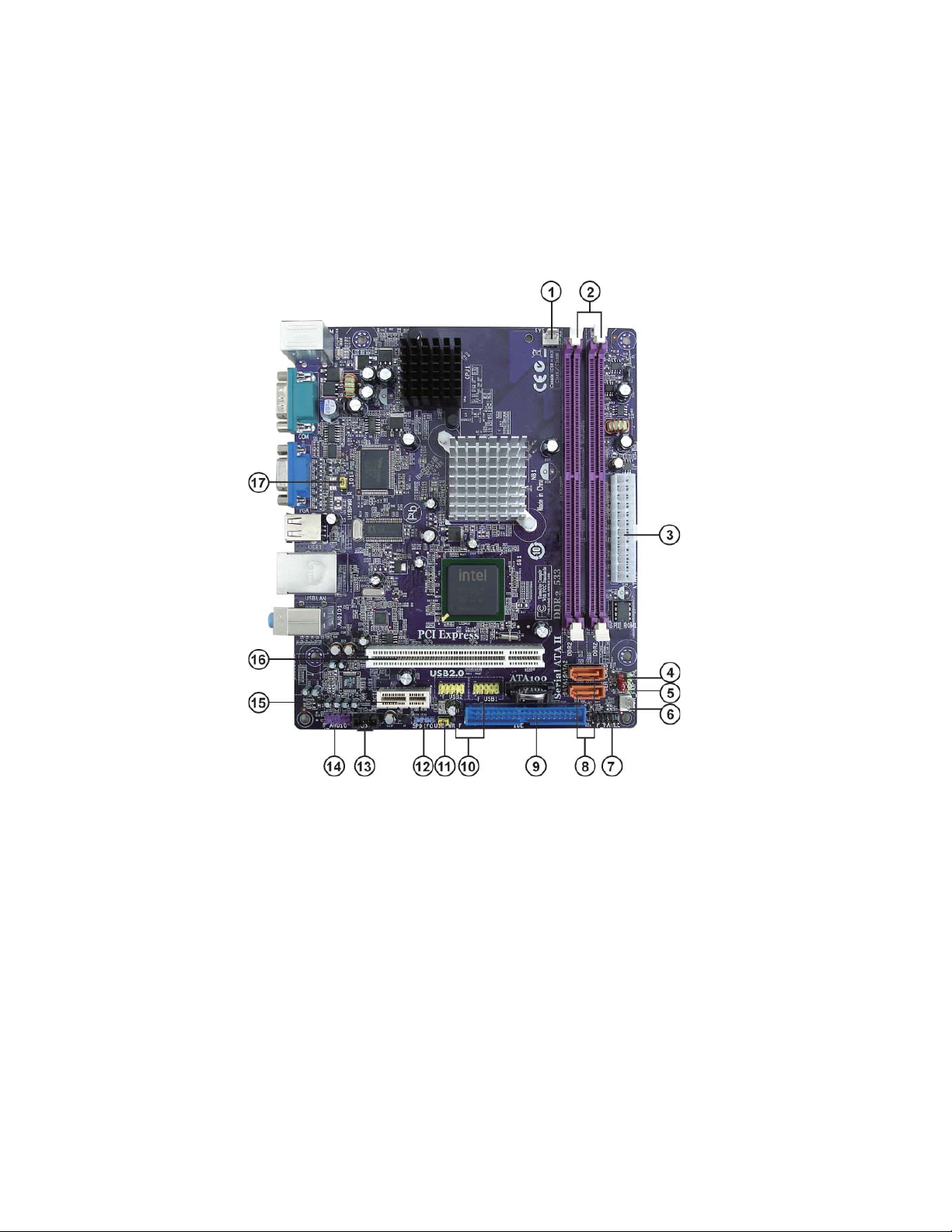
MotherboardComponents

5
IntroducingtheMotherboard
Table of Motherboard Components
LABEL COMPONENTS
1. SYS_FAN System cooling fan connector
2. DDR2_1~2 240-pin DDR2 SDRAM slots
3. ATX1 Standard 24-pin ATX power connector
4. CLR_CMOS Clear CMOS jumper
5. SPK Internal speaker header
6. PWR_FAN Power cooling fan connector
7. F_PANEL Front panel switch/LED header
8. SATA1~2 Serial ATA connectors
9. IDE Primary IDE connector
10. F_USB1~2 Front Panel USB headers
11. USBPWR_F Front Panel USB Power Select jumper
12. SPDIFO SPDIF out header
13. CD_IN Analog audio input connector
14. F_AUDIO Front panel audio header
15. PCIE PCI Express x1 slot
16. PCI 32-bit add-on card slot
17. USBPWR_R Rear USB/PS2 Power Select jumper
This concludes Chapter 1. The next chapter explains how to install the motherboard.

6
IntroducingtheMotherboard
Memo

7
InstallingtheMotherboard
Chapter2
InstallingtheMotherboard
SafetyPrecautions
• Follow these safety precautions when installing the motherboard
• Wear a grounding strap attached to a grounded device to avoid dam-
age from static electricity
• Discharge static electricity by touching the metal case of a safely
grounded object before working on the motherboard
• Leave components in the static-proof bags they came in
• Hold all circuit boards by the edges. Do not bend circuit boards
ChoosingaComputer Case
There are many types of computer cases on the market. The motherboard complies
with the specifications for the Micro DTX system case. First, some features on the
motherboard are implemented by cabling connectors on the motherboard to indica-
tors and switches on the system case. Make sure that your case supports all the
features required. Secondly, this motherboard supports two enhanced IDE drives.
Make sure that your case has sufficient power and space for all drives that you intend
to install.
Most cases have a choice of I/O templates in the rear panel. Make sure that the I/O
template in the case matches the I/O ports installed on the rear edge of the
motherboard.
This motherboard carries a Micro DTX form factor of 200 x 170 mm. Choose a case
that accommodates this form factor.
InstallingtheMotherboardin a Case
Refer to the following illustration and instructions for installing the motherboard in
a case.
Most system cases have mounting brackets installed in the case, which correspond
the holes in the motherboard. Place the motherboard over the mounting brackets
and secure the motherboard onto the mounting brackets with screws.
Ensure that your case has an I/O template that supports the I/O ports and expansion
slots on your motherboard.

8
InstallingtheMotherboard
CheckingJumperSettings
This section explains how to set jumpers for correct configuration of the motherboard.
SettingJumpers
Use the motherboard jumpers to set system configuration options. Jumpers with
more than one pin are numbered. When setting the jumpers, ensure that the jumper
caps are placed on the correct pins.
The illustrations show a 2-pin jumper. When
the jumper cap is placed on both pins, the
jumper is SHORT. If you remove the jumper
cap, or place the jumper cap on just one pin,
the jumper is OPEN.
This illustration shows a 3-pin jumper. Pins
1 and 2 are SHORT.
SHORT OPEN
Do not over-tighten the screws as this can stress the motherboard.
9
InstallingtheMotherboard
Checking Jumper Settings
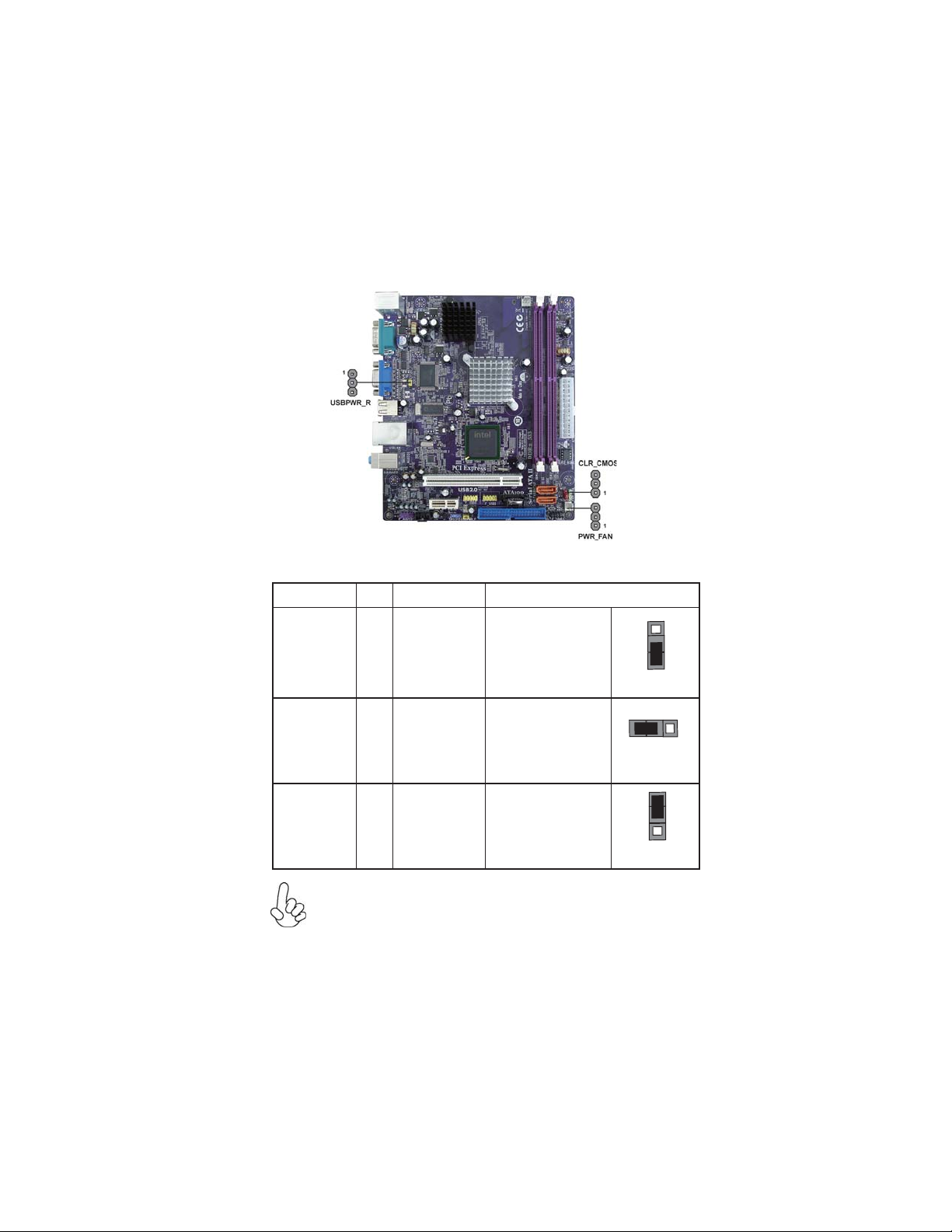
The following illustration shows the location of the motherboard jumpers. Pin 1 is
labeled.
JumperSettings
To avoid the system instability after clearing CMOS, we recommend
users to enter the main BIOS setting page to “Load Optimized Defaults”
and then “Save & Exit Setup”.
1.
2. Make sure the power supply provides enough VCC5_DUAL voltage
before selecting the VCC5_DUAL function.
3. It is required that users place the USBPWR_F & USBPWR_R cap onto
2-3 pin rather than 1-2 pin as default if you want to wake up the com-
puter by USB/PS2 KB/Mouse.
Jumper Type Description Setting (default)
CLR_CMOS 3-pin CLEAR CMOS
1-2: NORMAL
2-3: CLEAR CMOS
Before clearing the
CMOS, make sure to
turn the system off.
3-pin
USBPWR_R
1-2: VCC5
2-3: VCC5_DUAL
Rear USB/PS2
Power Select
Jumper
3-pin
USBPWR_F
1-2: VCC5
2-3: VCC5_DUAL
Front Panel
USB Power
Select Jumper
USBPWR_R
CLR_CMOS
1
1
USBPWR_F
1

10
InstallingtheMotherboard
ConnectingCaseComponents
After you have installed the motherboard into a case, you can begin connecting the
motherboard components. Refer to the following:
1 Connect the system cooling fan connector to SYS_FAN.
2 Connect the power cooling fan connector to PWR_FAN.
3 Connect the case switches and indicator LEDs to the F_PANEL.
4 Connect the standard power supply connector to ATX1.
5 Connec the case speaker cable to SPK.
Users please note that the 24-pin power cable can be connected to the
ATX1 connector.
With ATX v2.x power supply, users please
note that when installing 24-pin power
cable, the latches of power cable and the
ATX1 match perfectly.
Connecting 24-pin power cable
24-pin power cable
11
InstallingtheMotherboard
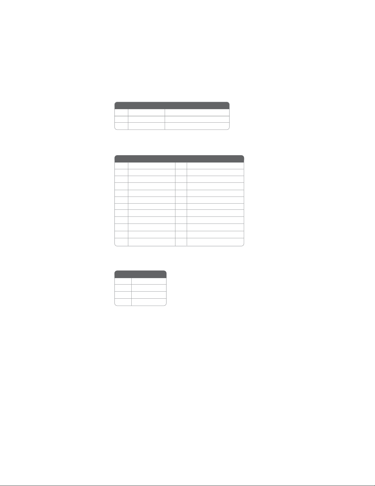
ATX1: ATX 24-pin Power Connector
SPK: Internal speaker header
Pin Signal Name Pin Signal Name
1+3.3V 13 +3.3V
2+3.3V 14 -12V
3Ground 15 Ground
4+5V 16 PS_ON
5Ground 17 Ground
6+5V 18 Ground
7Ground 19 Ground
8PWRGD 20 -5V
9+5VSB 21 +5V
10 +12V 22 +5V
11 +12V 23 +5V
12 +3.3V 24 Ground
4Signal
3GND
2Key
1VCC
Pin Signal Name
Pin Signal Name Function
1GND System Ground
2+12V Power +12V
3 Sense Sensor
SYS_FAN/PWR_FAN:FANPower Connectors

12
InstallingtheMotherboard
Front Panel Header
The front panel header (F_PANEL) provides a standard set of switch and LED
headers commonly found on ATX or Micro ATX cases. Refer to the table below for
information:
Pin Signal Function Pin Signal Function
1 HD_LED_P Hard disk LED(+) 2 FP PWR/SLP *MSG LED(+)
3 HD_LED_N Hard disk LED(- )
5 RST_SW_N Reset Switch(-)
7 RST_SW_P Reset Switch(+)
9 RSVD Reserved
4 FP PWR/SLP *MSG LED(-)
6 PWR_SW_P Power Switch(+)
8 PWR_SW_N Power Switch(-)
10 Key No pin
* MSG LED (dual color or single color)
Hard Drive Activity LED
Connecting pins 1 and 3 to a front panel mounted LED provides visual indication
that data is being read from or written to the hard drive. For the LED to function
properly, an IDE drive should be connected to the onboard IDE interface. The LED
will also show activity for devices connected to the SCSI (hard drive activity LED)
connector.
Power/Sleep/Message waiting LED
Connecting pins 2 and 4 to a single or dual-color, front panel mounted LED provides
power on/off, sleep, and message waiting indication.
Reset Switch
Supporting the reset function requires connecting pin 5 and 7 to a momentary-
contact switch that is normally open. When the switch is closed, the board resets and
runs POST.
Power Switch
Supporting the power on/off function requires connecting pins 6 and 8 to a momen-
tary-contact switch that is normally open. The switch should maintain contact for
at least 50 ms to signal the power supply to switch on or off. The time requirement
is due to internal de-bounce circuitry. After receiving a power on/off signal, at least
two seconds elapses before the power supply recognizes another on/off signal.

13
InstallingtheMotherboard
Installing Memory Modules
This motherboard accommodates two memory modules. It can support two 240-pin
DDR2 533/400. The total memory capacity is 2 GB.
You must install at least one module in any of the two slots. Each module can be
installed with 1 GB of memory; total memory capacity is 2 GB.
Do not remove any memory module from its antistatic packaging
until you are ready to install it on the motherboard. Handle the
modules only by their edges. Do not touch the components or metal
parts. Always wear a grounding strap when you handle the modules.
Installation Procedure
Refer to the following to install the memory modules.
1 This motherboard supports unbuffered DDR2 SDRAM .
2 Push the latches on each side of the DIMM slot down.
3 Align the memory module with the slot. The DIMM slots are keyed with
notches and the DIMMs are keyed with cutouts so that they can only be
installed correctly.
4 Check that the cutouts on the DIMM module edge connector match the
notches in the DIMM slot.
5 Install the DIMM module into the slot and press it firmly down until it
seats correctly. The slot latches are levered upwards and latch on to
the edges of the DIMM.
6 Installany remaining DIMM modules.
DDR2 SDRAM memory module table
DDR2 533 266 MHz
200 MHz
Memory module Memory Bus
DDR2 400

14
InstallingtheMotherboard
Table A: DDR2 (memory module) QVL (Qualified Vendor List)
The following DDR2 533/400 memory modules have been tested and qualified for use
with this motherboard.
Type Size Vendor Module Name
256 MB Samsung M378T3354BZ0-CCC
K4T51163QB-ZCCC
Samsung M378T6553BG0-CCC
K4T51083QB-GCCC
DDR2 400 512 MB TwinMos Samsung K4T51083QB-GCCC
Corsair VC256MB533D2 4PB11D9CHM
Eipida Japan E2508AA-T7F-E
Kingmax Hynix HY5PS121621
Nanya Nanya NT5TU32M16AG-37B
Ramaxel Elpida D5116AF-5C-E
256 MB
Ramaxel 5PB42 D9DCD
Aeneon Aeneon AET94F370 DS
Aeneon Aeneon AET93F370 SS
Corsair Samsung K4T51083QB-ZCD5
Corsair VS512MB533D2 64M8CEC
Eipida Elpida 04180WB01
Hynix Hynix HY5PS12821
Infineon HY818T512800AF37 33346778
Kingston Hynix HY5PS12821
Kingston Nanya NT5TU64M8AE-37B
Ramaxel 5PB32 D9DCN
Ramaxel Elpida E5108AG-5C-E
Ramaxel 6AD11 D9GCT
Samsung PC2-4200U-4444-10-B1
K4T56083QF-ZCD5
Samsung PC2-4200U-4444-12-DS
K4T51083QC
Twinmos Samsung 8D22JB-KM
512 MB
Twinmos Elpida E5108AB-5C-E
Apacer Elpida E5108AB-5C-E
Geil A016E2864T2AG8AKT5H120001
Infineon HY818T512800AF37 33344539
Kingmax KKEA88E4AAKG-37
DDR2 533
1 GB
UMAX U2S12D30TP-5C
Table of contents
Other ECS Motherboard manuals

ECS
ECS kt600-a User manual

ECS
ECS TIGD-CI3 User manual

ECS
ECS B75H2-M3 User manual

ECS
ECS DURATHON 2 B150M-P73 User manual

ECS
ECS H61H2-M3 User manual

ECS
ECS 865GV-M3 Series User manual

ECS
ECS H81H3-TI2 User manual

ECS
ECS EX-OR HP2000 Installation manual

ECS
ECS NFORCE6M-A User manual

ECS
ECS Durathon 2 User manual


Popular Motherboard manuals by other brands

Asus
Asus Z97-K/USB3.1 manual

Texas Instruments
Texas Instruments DS90UB95 Q1EVM Series user guide

Giacomini
Giacomini K471 Operating instructions and guarantee

ASROCK
ASROCK Z68 EXTREME4 - ANNEXE 541 user manual
 user manual")
Gigabyte
Gigabyte GA-K8VT800(Pro) user manual

ON Semiconductor
ON Semiconductor NCP1060 user manual


