ECS A875M-A User manual

Preface
Preface
Copyright
This publication, including all photographs, illustrations and software, is protected
under international copyright laws, with all rights reserved. Neither this manual, nor
any of the material contained herein, may be reproduced without written consent of
the author.
Version 1.0
Disclaimer
The information in this document is subject to change without notice. The manufac-
turer makes no representations or warranties with respect to the contents hereof and
specifically disclaims any implied warranties of merchantability or fitness for any
particular purpose. The manufacturer reserves the right to revise this publication and
to make changes from time to time in the content hereof without obligation of the
manufacturer to notify any person of such revision or changes.
FederalCommunicationsCommission(FCC)
This equipment has been tested and found to comply with the limits for a Class B
digital device, pursuant to Part 15 of the FCC Rules. These limits are designed to
provide reasonable protection against harmful interference in a residential installa-
tion. This equipment generates, uses, and can radiate radio frequency energy and, if
not installed and used in accordance with the instructions, may cause harmful inter-
ference to radio communications. However, there is no guarantee that interference
will not occur in a particular installation. If this equipment does cause harmful
interference to radio or television reception, which can be determined by turning the
equipment off and on, the user is encouraged to try to correct the interference by one
or more of the following measures:
• Reorient or relocate the receiving antenna.
• Increase the separation between the equipment and the receiver.
• Connect the equipment onto an outlet on a circuit different from that to
which the receiver is connected.
• Consult the dealer or an experienced radio/TV technician for help.
Shielded interconnect cables and a shielded AC power cable must be employed with
this equipment to ensure compliance with the pertinent RF emission limits govern-
ing this device. Changes or modifications not expressly approved by the system’s
manufacturer could void the user’s authority to operate the equipment.
TrademarkRecognition
Microsoft, MS-DOS and Windows are registered trademarks of Microsoft Corp.
AMD, Phenom, Athlon, Sempron and Duron are registered trademarks of AMD
Corporation.
Other product names used in this manual are the properties of their respective
owners and are acknowledged.

ii
Preface
DeclarationofConformity
This device complies with part 15 of the FCC rules. Operation is subject to the
following conditions:
• This device may not cause harmful interference, and
• This device must accept any interference received, including interfer-
ence that may cause undesired operation.
CanadianDepartmentofCommunications
This class B digital apparatus meets all requirements of the Canadian Interference-
causing Equipment Regulations.
Cet appareil numérique de la classe B respecte toutes les exigences du Réglement sur
le matériel brouilieur du Canada.
AbouttheManual
The manual consists of the following:
Chapter 1
Introducing the Motherboard
Describes features of the motherboard.
Go to Hpage 1
Describes installation of motherboard
components.
Go to Hpage 7
Provides information on using the BIOS
SetupUtility.
Go to Hpage 25
Describes the motherboard software
Go to Hpage 45
Provides information about SATA RAID
Setup
Go to Hpage 49
Chapter 5
Setting Up AMD SB850 RAID
Configuration
page 67
Chapter 7
TroubleShooting
Provides basic troubleshooting tips
Go to H
Chatper 6
SettingUp eJIFFY Describes the eJIFFY setting up
Go to Hpage 57
Chapter 2
Installing the Motherboard
Chapter 3
UsingBIOS
Chapter 4
Using the Motherboard Software

iii
TT
TT
TABLE OF CONTENTSABLE OF CONTENTS
ABLE OF CONTENTSABLE OF CONTENTS
ABLE OF CONTENTS
Preface i
Chapter 1 1
IntroducingtheMotherboard 1
Introduction............................................................................................1
Features...................................................................................................2
MotherboardComponents...................................................................4
Chapter 2 77
77
7
Installing the Motherboard 7
SafetyPrecautions...............................................................................7
Choosinga ComputerCase..................................................................7
Installingthe Motherboard in aCase.................................................7
CheckingJumperSettings....................................................................8
Setting Jumpers...............................................................................8
Checking Jumper Settings...............................................................9
Jumper Settings...............................................................................9
InstallingHardware..........................................................................10
Installing the Processor.................................................................10
Installing Memory Modules...........................................................11
Expansion Slots.............................................................................15
Connecting Optional Devices........................................................17
Installing a SATA Hard Drive.......................................................19
ConnectingI/O Devices...................................................................20
ConnectingCase Components..........................................................21
Front Panel Header.......................................................................24
Chapter 3 2525
2525
25
UsingBIOS 25
About the SetupUtility....................................................................25
The Standard Configuration..........................................................25
Entering the Setup Utility...............................................................25
Resetting the Default CMOS Values...............................................26
UsingBIOS............................................................................................27
Standard CMOS Setup..................................................................28
Advanced Setup.............................................................................30
Advanced Chipset Setup................................................................32

iv
Integrated Peripherals..................................................................32
Power Management Setup.............................................................33
PCI/PnP Setup...............................................................................34
PC Health Status............................................................................35
M.I.B. III (MB Intelligent Bios)......................................................38
Load Default Settings....................................................................40
Load Non Disk..............................................................................40
Supervisor Password.....................................................................42
User Password...............................................................................43
Save & Exit Setup ..........................................................................43
Exit Without Saving........................................................................43
Updating the BIOS.........................................................................44
Chapter 4 4545
4545
45
UsingtheMotherboardSoftware 45
Aboutthe SoftwareDVD-ROM/CD-ROM......................................45
Auto-installingunderWindowsXP/Vista/7.....................................45
Running Setup...............................................................................46
ManualInstallation...........................................................................48
UtilitySoftware Reference................................................................48
Chapter 5 4949
4949
49
SettingUpAMDSB850RAIDConfiguration 49
Setting Upa Bootable RAIDArray...................................................49
Chapter 6 5757
5757
57
SettingUpeJIFFY 57
Introduction..........................................................................................57
Installationand BIOSSetup.................................................................58
Entering eJIFFY.............................................................................................61
Features Icons...............................................................................................62
Usage FAQ................................................................................................63
Chapter 7 6767
6767
67
TroubleShooting 67
Startup problems during assembly....................................................67
Startup problems after prolong use..................................................68
Maintenanceand care tips..................................................................68
BasicTroubleshooting Flowchart......................................................69

1
IntroducingtheMotherboard
Chapter1
IntroducingtheMotherboard
Introduction
Thank you for choosing the A875M-A motherboard. This motherboard is a high
performance, enhanced function motherboard that supports socket for AMD
PhenomTM II/AthlonTM II/SempronTM processors (socket AM3) for high-end business
or personal desktop markets.
There is an advanced full set of I/O ports in the rear panel, including PS/2 mouse and
keyboard connectors, one serial port, one eSATA port, eight USB ports, one LAN
port and audio jacks for microphone, line-in and 6/8-ch line-out.
The motherboard incorporates the AMD 870 Northbridge (NB) and SB850 Southbridge
(SB) chipsets. The Northbridge supports the HyperTransportTM 3.0 interface. The
memory controller supports DDR3 memory DIMM frequencies of 1600(OC)/1333/
1066/800*1. It supports four DDR3 slots with maximum memory size of 32 GB*2.
One PCI Express x16 slot, intended for Graphics Interface, is fully compliant to the
PCI Express Gen2 (version 2.0). In addition, two PCI Express x1 slots are supported.
*2. Due to the DRAM maximum size (4 GB per dimm) at present, the
memory maximum size we have tested is 16 GB.
*1. Due to the limitation of AMD CPU spec, please refer to Memory QVL
for more information.
The SB850 Southbridge supports three PCI slots which are PCI v2.3 compliant. It
integrates USB 2.0 interface, supporting up to fourteen functional ports (eight USB
ports and three USB 2.0 headers support additional six USB ports). The Southbridge
integrates a Serial ATA host controller, supporting five SATA ports with maximum
transfer rate up to 6.0 Gb/s each and one eSATA port with maximum transfer rate up
to 3.0 Gb/s.

2
IntroducingtheMotherboard
Feature
Processor
HyperTransportTM Technology is a point-to-point link between two devices, it
enables integrated circuits to exchange information at much higher speeds than
currently available interconnect technologies.
• Accommodates AMD PhenomTM II/AthlonTM II/SempronTM processors
(socket AM3)
• Supports HyperTransportTM (HT) 3.0 interface speeds
This motherboard uses a socket AM3 that carries the following features:
SB850 (SB)
AMD 870
(NB)
• Supports one x16 PCI Express (PCI-E) link for graph-
ics.
• Supports 16-bit up/down HyperTransport(HT)3.0 in-
terface.
• Fully supports ACPI states S1, S3, S4 and S5
• Supports ATI HyperMemory*.
Note: Includes dedicated and shared memory. The amount
of HyperMemory available is determined by various
factors. For details, please consult your AMD CSS
representative.
• Supports 16-bit up/down HyperTransport (HT) 3.0 in-
terface up to 5.2 GT/s.
The AMD 870 Northbridge (NB) and SB850 Southbridge (SB) chipsets are based
on an innovative and scalable architecture with proven reliability and perfor-
mance.
Chipset
Memory
• Supports DDR3 1600 (OC)/1333/1066/800 SDRAM with Dual-channel
architecture
• Accommodates four unbuffered DIMMs
• Up to 8 GB per DIMM with maximum memory size up to 32 GB*2
• Compliant with PCI 2.3 specification at 33 MHz
• Supports five Serial ATA devices which speeds up to
6.0 Gb/s
• Supports one External Serial ATA device which speed
up to 3.0Gb/s
• Integrated USB 2.0 Host Controller supporting up to
fourteen USB 2.0 ports
• Supportsintegrated RAID 0, RAID1, RAID 5, andRAID
10 functionality across all 5 ports (RAID 10 requires
use of 4 or more SATAports, and RAID 5 requires use
of 3 or more SATA ports)
3
IntroducingtheMotherboard
Expansion Options
The motherboard comes with the following expansion options:
• One PCI Express x16 slot for Graphics Interface
• Two PCI Express x1 slots
• Three 32-bit PCI v2.3 compliant slots
• Five 7-pin SATA connectors
Integrated I/O
• Two PS/2 ports for mouse and keyboard connectors
• One eSATA port
• One serial port
• Eight USB ports
• One LAN port
• Audio jacks for microphone, line-in and 6/8-ch line-out
BIOS Firmware
• Power management
• Wake-up alarms
• CPUparameters
• CPUandmemorytiming
The firmware can also be used to set parameters for different processor clock
speeds.
The motherboard uses AMI BIOS that enables users to configure many sys-
tem features including the following:
1. Some hardware specifications and software items are subject to change
without prior notice.
2. Due to chipset limitation, we recommend that motherboard be operated in
the ambiance between 0 and 50°C.
Onboard LAN
• Supports PCI ExpressTM 1.1
• Integrated 10/100/1000 transceiver
• Wake-on-LAN and remote wake-up support
• 5.1 Channel High DefinitionAudio Codec
• ADCs support 44.1k/48k/96kHz sample rate
• Meets Microsoft WLP 3.10 Vista premium and mobile PCs audio
requirements
• Direct Sound 3DTM compatible
Audio (Optional)
• 7.1+2 Channel High DefinitionAudio Codec
• Meets Microsoft WLP 3.10 Vista premium and mobile PCs audio
requirements
• All DACs support 44.1k/48k/96k/192kHz sample rate
• Software selectable 2.5V/3.2V/4.0V VREFOUT
• Direct Sound 3DTM compatible
• Power Support: Digital: 3.3V; Analog: 5.0V

4
IntroducingtheMotherboard
• NB:AMD 870 SB: SB850
•AMD PhenomTM II/AthlonTM II/SempronTM processors (socket
AM3)
• Supports “Hyper-Threading” technology CPU
• Dual-channel DDR3 memory architecture
• 4 x 240-pin DDR3 DIMM sockets support up to 32 GB
• Supports DDR3 1600 (OC)/1333/1066/800 SDRAM
• 1 x PCI Express Gen2 x16 slot
• 2 x PCI Express Gen2 x1 slots
• 3 x PCI slots
• Supported by AMD SB850 Express Chipset
• 5 x Serial ATA 6.0 Gb/s Host Controllers
• 1 x eSATA 3.0 Gb/s
• ALC892 6-Channel / ALC662 6-Channel (Optional)
• Realtek8111EPCIE GigaLAN Controller
• 1 x PS/2 Keyboard & Mouse connectors
• 1 x Serial port
• 1 x eSATA port
• 8 x USB ports
• 1 x RJ45 LAN connector
• 1 x Audio port (Line in, microphone in, 6/8-ch line out)
• 1 x 24-pin ATX Power Supply connector
• 1 x 8-pin ATA connector
• 5 x Serial ATA connectors
• 3 x USB 2.0 headers support additional 6 USB ports
• 1 x Front panel header
• 1x CLR_CMOS jumper
• 1 x SPDIF out header
• 1 x Front panel audio header
• 1 x Speaker header
• CPU_FAN/SYS_FAN/PWR_FAN connectors
Chipset
Memory
Expansion
Slots
Storage
Audio
LAN
RearPanelI/O
InternalI/O
Connectors &
Headers
• AMIBIOS with 8Mb SPIROM
• Supports Plug and Play 1.0A,APM 1.2, Multi Boot, DMI
• Supports ACPI revision 1.0 specification
SystemBIOS
FormFactor • ATX Size, 305mm x 210mm
CPU
Specifications
• Supports RAID 0, 1, 5 and 10

5
IntroducingtheMotherboard
MotherboardComponents
The above image is for reference only; please take the actual
motherboard for detailed parts.

6
IntroducingtheMotherboard
Table of Motherboard Components
LABEL COMPONENTS
1. CPU Socket Socket for AMD PhenomTM II/AthlonTM II/SempronTM
processors (socket AM3)
2. CPU_FAN CPU cooling fan connector
3. DDR3_1~4 240-pin DDR3 SDRAM slots
4. ATX_POWER Standard 24-pin ATX power connector
5. PWR_FAN Power cooling fan connector
6. SATA1~5 Serial ATA connectors
7. USBPWR_F1~2 Front panel USB power select jumpers
8. F_PANEL Front panel switch/LED header
9. SPK Speaker header
10. F_USB1~4 Front Panel USB headers
11. CLR_CMOS Clear CMOS jumper
12. SYS_FAN System cooling fan connector
13. SPDIFO SPDIF out header
14. F_AUDIO Front panel audio header
15. PCI1~3 32-bit add-on card slots
16. PCIEX16 PCI Express x16 slot for graphics interface
17. PCIE1~2 PCI Express x1 slots
18. USBPWR_R1~2 Rear USB/PS2 power select jumpers
19. ATX12V 8-pin +12V power connector
This concludes Chapter 1. The next chapter explains how to install the motherboard.

7
InstallingtheMotherboard
Chapter2
InstallingtheMotherboard
SafetyPrecautions
• Follow these safety precautions when installing the motherboard
• Wear a grounding strap attached to a grounded device to avoid dam-
age from static electricity
• Discharge static electricity by touching the metal case of a safely
grounded object before working on the motherboard
• Leave components in the static-proof bags they came in
• Hold all circuit boards by the edges. Do not bend circuit boards
ChoosingaComputerCase
There are many types of computer cases on the market. The motherboard complies
with the specifications for the ATX system case. Some features on the motherboard
are implemented by cabling connectors on the motherboard to indicators and switches
on the system case. Make sure that your case supports all the features required. Make
sure that your case has sufficient power and space for all drives that you intend to
install.
Most cases have a choice of I/O templates in the rear panel. Make sure that the I/O
template in the case matches the I/O ports installed on the rear edge of the
motherboard.
This motherboard carries an ATX form factor of 305 X 210 mm. Choose a case that
accommodates this form factor.
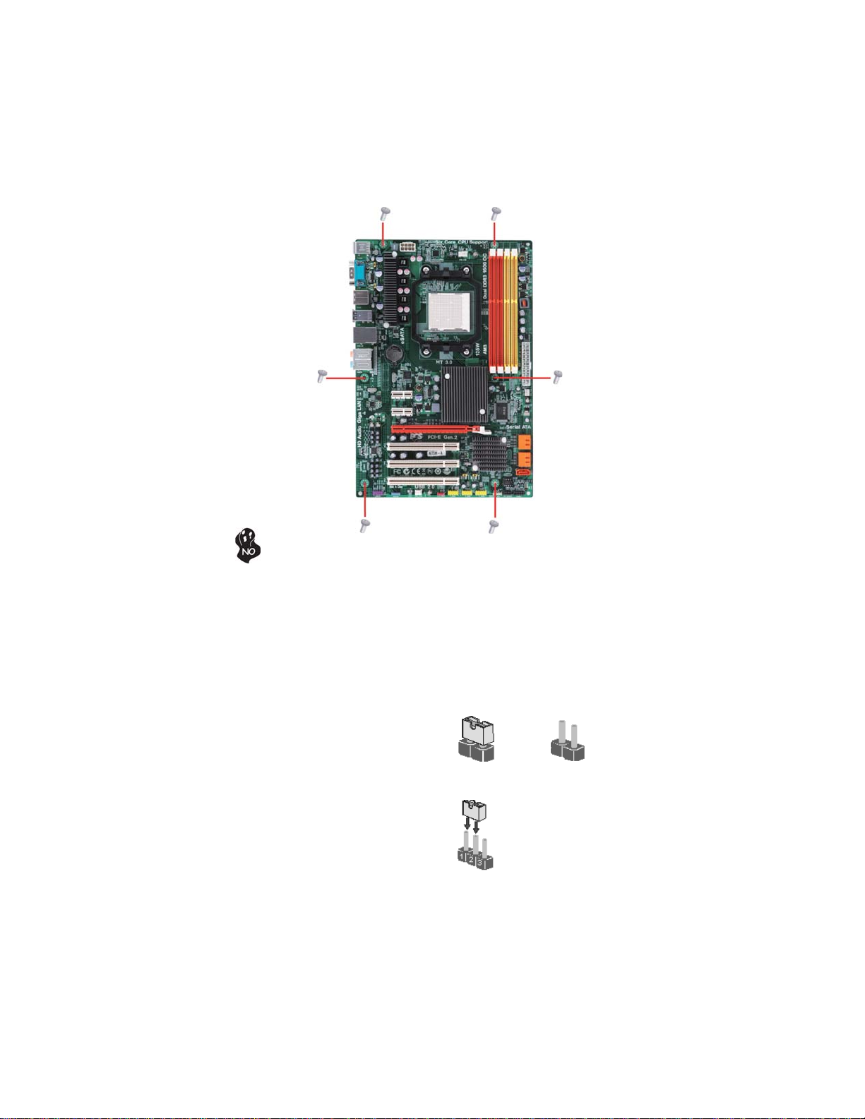
InstallingtheMotherboard in a Case
Refer to the following illustration and instructions for installing the motherboard in
a case.
Most system cases have mounting brackets installed in the case, which correspond
the holes in the motherboard. Place the motherboard over the mounting brackets
and secure the motherboard onto the mounting brackets with screws.
Ensure that your case has an I/O template that supports the I/O ports and expansion
slots on your motherboard.
8
InstallingtheMotherboard
Do not over-tighten the screws as this can stress the motherboard.
CheckingJumperSettings
This section explains how to set jumpers for correct configuration of the motherboard.
SettingJumpers
Use the motherboard jumpers to set system configuration options. Jumpers with
more than one pin are numbered. When setting the jumpers, ensure that the jumper
caps are placed on the correct pins.
The illustrations show a 2-pin jumper. When
the jumper cap is placed on both pins, the
jumper is SHORT. If you remove the jumper
cap, or place the jumper cap on just one pin,
the jumper is OPEN.
This illustration shows a 3-pin jumper. Pins
1 and 2 are SHORT.
SHORT OPEN

9
InstallingtheMotherboard
Checking Jumper Settings
The following illustration shows the location of the motherboard jumpers. Pin 1 is
labeled.
JumperSettings
1. To avoid the system unstability after clearing CMOS, we recommend
users to enter the main BIOS setting page to “Load Default Settings” and
then “Save & Exit Setup”.
2. Make sure the power supply provides enough 5VSB voltage before
selecting the 5VSB function.
3. It is required that users place the USBPWR_R1~2 & USBPWR_F1~2
cap onto 2-3 pin rather than 1-2 pin as default if you want to wake up the
computer by USB/PS2 KB/Mouse.
Rear USB PS/2
Power Select
Jumper USBPWR_R1~2
Jumper Type Description Setting (default)
CLR_CMOS 3-pin Clear CMOS
1-2: NORMAL
2-3: CLEAR
Before clearing the
CMOS, make sure to
turn off the system. CLR_CMOS
1-2: VCC
USBPWR_R1~2 3-pin 2-3: 5VSB
USBPWR_F1~2
1-2: VCC
USBPWR_F1~2 3-pin 2-3: 5VSB
1
1
Front Panel
USB Power
Select Jumper
1

10
InstallingtheMotherboard
InstallingHardware
Installing the Processor
Caution: When installing a CPU heatsink and cooling fan make sure that
you DO NOT scratch the motherboard or any of the surface-mount resis-
tors with the clip of the cooling fan. If the clip of the cooling fan scrapes
across the motherboard, you may cause serious damage to the motherboard
or its components.
This motherboard has a socket AM3 processor socket. When choosing a processor,
consider the performance requirements of the system. Performance is based on the
processor design, the clock speed and system bus frequency of the processor, and the
quantity of internal cache memory and external cache memory.
Before installing the Processor
This motherboard automatically determines the CPU clock frequency and system
bus frequency for the processor. You may be able to change these settings by making
changes to jumpers on the motherboard, or changing the settings in the system Setup
Utility. We strongly recommend that you do not over-clock processors or other
components to run faster than their rated speed.
On most motherboards, there are small surface-mount resistors near the
processor socket, which may be damaged if the cooling fan is carelessly
installed.
Avoid using cooling fans with sharp edges on the fan casing and the clips.
Also, install the cooling fan in a well-lit work area so that you can clearly
see the motherboard and processor socket.
Warning:
1. Over-clocking components can adversely affect the reliability of the
system and introduce errors into your system. Over-clocking can perma-
nently damage the motherboard by generating excess heat in components
that are run beyond the rated limits.
2. Always remove the AC power by unplugging the power cord from the
power outlet before installing or removing the motherboard or other hard-
ware components.
Fail-Safe Procedures for Over-clocking
When end-users encounter failure after attempting over-clocking, please take
the following steps to recover from it.
1. Shut down the computer.
2. Press and hold the “Page Up Key (PgUp)” of the keyboard, and then boot the
PC up.
3. Two seconds after the PC boots up, release the “Page Up Key (PgUp)”.
4. The BIOS returns to the default setting by itself.
11
InstallingtheMotherboard
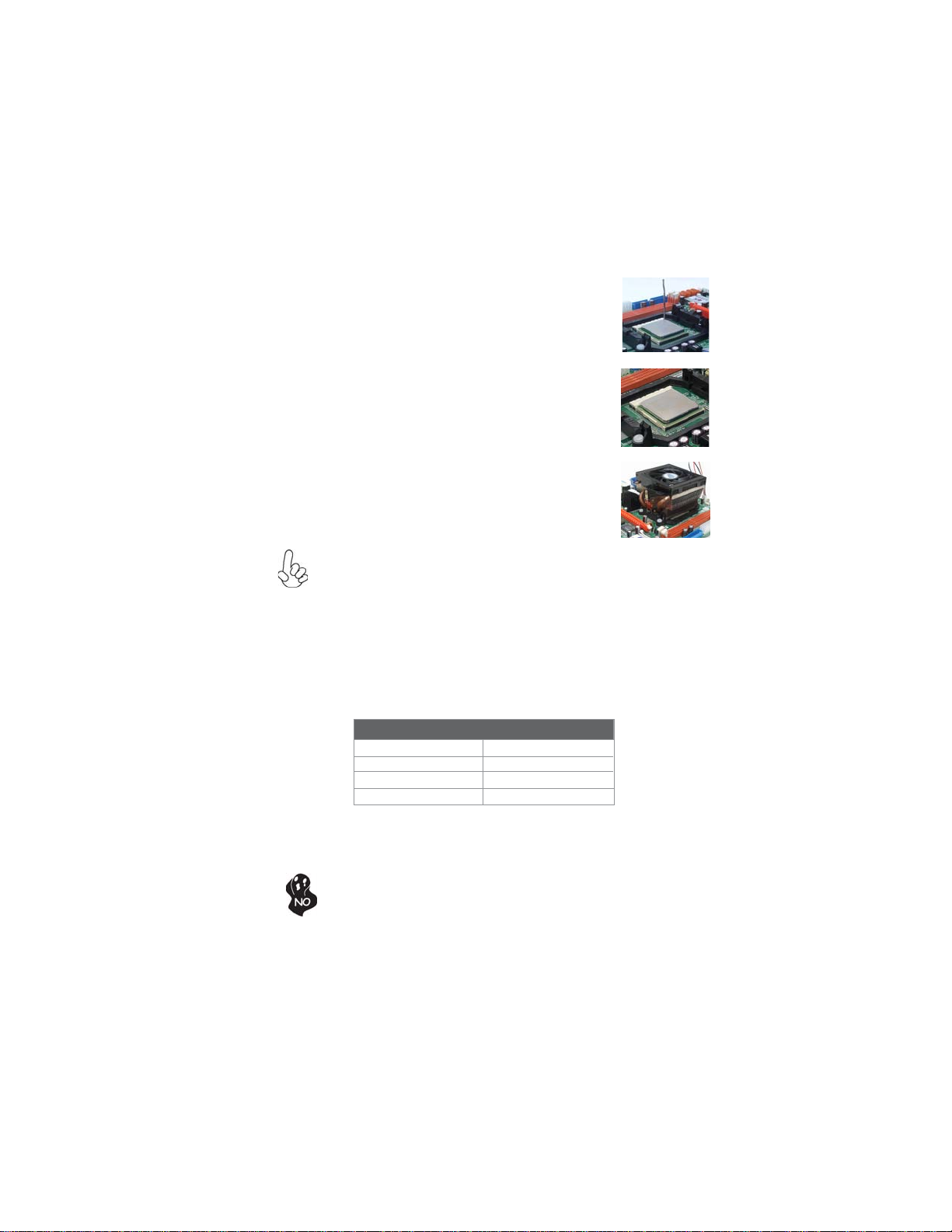
1 Install your CPU. Pull up the lever away from
the socket and lift up to 90-degree angle.
2 Locate the CPU cut edge (the corner with
the pin hold noticeably missing). Align and
insert the CPU correctly.
3 Press the lever down and apply thermal
grease on top of the CPU.
4 Put the CPU Fan down on the retention mod-
ule and snap the four retention legs of the
cooling fan into place.
5 Flip the levers over to lock the heat sink in
placeandconnecttheCPUcoolingFanpower
cable to the CPUFAN connector. This com-
pletes the installation.
CPU Installation Procedure
The following illustration shows CPU installation components.
To achieve better airflow rates and heat dissipation, we suggest that you
use a high quality fan with 4800 rpm at least. CPU fan and heatsink
installation procedures may vary with the type of CPU fan/heatsink sup-
plied. The form and size of fan/heatsink may also vary.
Installing Memory Modules
This motherboard accommodates four memory modules. It can support four 240-pin
DDR3 1600(OC)/1333/1066/800. The total memory capacity is 32 GB.
DDR3 SDRAM memory module table
Do not remove any memory module from its antistatic packaging until
you are ready to install it on the motherboard. Handle the modules only
by their edges. Do not touch the components or metal parts. Always
wear a grounding strap when you handle the modules.
You must install at least one module in any of the four slots. Each module can be
installed with 8 GB of memory.
Memory module Memory Bus
DDR3 1066 533 MHz
DDR3 1333 667 MHz
DDR3 800 400 MHz
DDR3 1600(OC) 800 MHz

12
InstallingtheMotherboard
Installation Procedure
Refer to the following to install the memory modules.
1 This motherboard supports unbuffered DDR3 SDRAM only.
2 Push the latches on each side of the DIMM slot down.
3 Align the memory module with the slot. The DIMM slots are keyed with
notches and the DIMMs are keyed with cutouts so that they can only be
installed correctly.
4 Check that the cutouts on the DIMM module edge connector match the
notches in the DIMM slot.
5 Install the DIMM module into the slot and press it firmly down until it
seats correctly. The slot latches are levered upwards and latch on to
the edges of the DIMM.
6 Installany remaining DIMM modules.
For best performance and compatibility, we recommend that users install
DIMMs in the sequence of DIMM3, DIMM4, DIMM1 and DIMM2.
Recommend configuration for best performance and compatibility
: operation with normal performance
: operation with the best performance
Number of DIMMs DIMM 1 DIMM 2 DIMM 3 DIMM 4 AM3
1Single Channel
2Dual Channel
3Dual Channel
4Dual Channel

13
InstallingtheMotherboard
Table A: DDR3(memory module) QVL (Qualified Vendor List)
The following DDR3 memory modules have been tested and qualified for use with this
motherboard.
NO. Vendor Module Part Number IC Brand IC Chip Number SS/DS Size
1Qimonda IMSH51U03A1F1C-08E Qimonda IDSH51-03A1F1C-0BE SS 512 MB
NO. Vendor Module Part Number IC Brand IC Chip Number SS/DS Size
1 Elixir M2Y2G64CB8HC9N-BE DS 2GB
2Elixir M2Y2G64CB8HC5N-BE elixir N2CB1G80CN-BE DS 2GB
3Elpida PC3-8500U-7-00-AP Elpida J53088ASE-AC-E SS 512MB
4Hynix HYMT112U64ZNF8-G8 AA Hynix HY5TQ1G831ZNFP-G8 SS 1GB
5Hynix HMT112U6AFP8C-G7N0 AA Hynix H5TQ1G83AFPG7C SS 1GB
6Hynix HYMT125U64ZNF8-G8 AA Hynix HY5TQ1G831ZN FP-G8 DS 2GB
7Hynix HMT125U6AFP8C-G7N0 AA Hynix H5TQ1G83AFPG7C DS 2GB
8Kingston KVR1066D3N7 Elpida J5308BASE-AE-E07500W220 DS 1GB
9Micron MT8JTF12864AY-1G1D1 Micron 7UD22D9JNL SS 1GB
10 Micron MT8JTF12864AY-1G1D1 Micron 8TD22 D9JNL SS 1GB
11 Micron MT16JTF25664AY-1G1D1 Micron 7UD22D9JNL DS 2GB
12 Micron MT16JTF25664AY-1G1D1 Micron 8WD22 D9JNL DS 2GB
13 Micron MT16JTF25664AZ-1G1F1 Micron 9EF22 D9KPV DS 2GB
14 Micron MT8JTF12864AZ-1G1F1 Micron 9NF22 D9KPT SS 1GB
15 Ramexel RMR1810NA48E7F-1066-LF NANYA NT5CB128H8AN-DE SS 1GB
16 Samsung M378B2873DZ1-CF8 SEC HCF8 K4B1G0846D SS 1GB
17 Samsung M378B5673DZ1-CF8 SEC K4B1G0846DHCF8 DS 2GB
18 Kingston KVR1066D3N7/512 Elpida J5308BASE-AE-E07340W065 SS 512MB
19 Qimonda IMSH1GU03A1F1C-10F Qimonda IDSH1G-03A1F1C-10F FSS15085 SS 1GB
20 Qimonda IMSH1GU03A1F1C-10G Qimonda IDSH1G-03A1F1C-10G FSS14526 SS 1GB
21 Qimonda IMSH2GU13A1F1C-10F Qimonda IDSH1G-03A1F1C-10F FSS15085 DS 2GB
22 Qimonda IMSH2GU13A1F1C-10G Qimonda IDSH1G-03A1F1C-10G FSS13467 DS 2GB
23 Hynix HYMT112U64ZNF8-G8 AA Hynix HY5TQ1G831ZNFP-G8 SS 1GB
24 Samsung M378B2873EH1-CF8 SEC HCF8K4B1G0846E SS 1GB
25 Samsung M378B5673DZ1-CF8 SEC K4B1G0846DHCF8 DS 2GB
26 Aeneon AEH760UD00-10FA98X Aeneon AEH93R10F 0737 SS 1GB
27 Elpida EBJ10UE8BDF0-AE-F Elpida J1108BDSE-DJ-F SS 1GB
28 Elpida EBJ21UE8BDF0-AE-F Elpida J1108BDSE-DJ-F DS 2GB
29 Nanya M2Y2G64TU8HD5B-BD elixir N2CB1G80AN-CG DS 2GB
NO. Vendor Module Part Number IC Brand IC Chip Number SS/DS Size
1 A-DATA AD3U1333B1G9-B Hynix H5TQ1G83BFR SS 1GB
2A-DATA AD3U1333B2G9-B Hynix H5TQ1G83BFR DS 2GB
3Apacer 78.A1GC6.9L1 Apacer AM5D5808ADWSBG DS 2GB
4Elixir M2F2G64CB8HA4N-CG Elixir N2CB1G80AN-CG 0903 DS 2GB
5Elixir M2Y2G64CB8HC9N-CG DS 2GB
6Hynix HMT112U6AFP8C-H9N0 AA Hynix H5TQ1G83AFPH9C SS 1GB
7Hynix HMT125U6AFP8C-H9N0 AA Hynix H5TQ1G83AFPH9C DS 2GB
8G.SKILL F3-10666CL9D-4GBRL DS 2GB
9G.SKILL F3-10666CL8D-4GBECO 1.35V DS 2GB
10 G.SKILL F3-10666CL9D-4GBNQ DS 2GB
DDR3 800
DDR3 1066
DDR3 1333

14
InstallingtheMotherboard
NO. Vendor Module Part Number IC Brand IC Chip Number SS/DS Size
11 Kingston KVR1333D3N9 Elpida J1108BASE-DJ-E SS 1GB
12 Kingston KVR1333D3N9 Elpida J1108BABG-DJ-E DS 2GB
13 Kingston KVR1333D3N9/4G Hynix Hynix/H5TQ2G83AFR DS 4GB
14 KingMax FLFD45F-B8KG9 NAES KingMax KFB8FNGXF-ANX-15A SS 1GB
15 KingMax FLFE85F-B8KG9 NEES KingMax KFB8FNGXF-ANX-15A DS 2GB
16 Nanya NT2GC64B8HAONF-CG Elixir N2CB1G80AN-CG DS 2GB
17 Micron MT8JTF12864AY-1G4D1 Micron 8UD22 D9JNM SS 1GB
18 Micron MT16JTF25664AY-1G4D1 Micron 8WD22 D9JNM DS 2GB
19 Micron MT8JTF12864AZ-1G4F1 Micron 9MF22 D9KPT SS 1GB
20 PSC AL7F8G73D-DG1 PSC A3P1GF3DGF SS 1GB
21 PSC AL8F8G73D-DG1 PSC A3P1GF3DGF DS 2GB
22 Ramaxel RMR1810KD48E7F-1333 SEC K4B1G0846D SS 1GB
23 Ramaxel RMR186EA48D8F-1333 ELPLDA J1108BASE-DJ-E DS 2GB
24 Samsung M378B2873DZ1-CH9 SEC K4B1G0846D SS 1GB
25 Samsung M378B2873EH1-CH9 SEC K4B1G0846E HCH9 SS 1GB
26 Samsung M378B5673EH1-CH9 SEC K4B1G0846E HCH9 DS 2GB
27 Samsung M378B2873FHS-CH9 SEC K4B1G0846F SS 1GB
28 Samsung M378B5673FH0-CH9 SEC K4B1G0846F DS 2GB
29 Samsung M378B5273CH0-CH9 SEC K4B2G0846C DS 4GB
30 Silicon SP001GBLTU133S01 Nanya NT5CB128M8AN-CG SS 1GB
31 Silicon SP002GBLTU133S01 Nanya NT5CB128M8AN-CG DS 2GB
32 Aeneon AXH760UD00-13GA98X SS 1GB
33 KingsMax FLFD45F-B8KG9 NAUS KingsMax KFB8FNGXF-ANX-15U SS 1GB
34 KingsMax FLFE85F-B8KG9 NEUS KingsMax KFB8FNGXF-ANX-15U DS 2GB
35 Kingston KVR1333D3N9 Kingston 128X8DDR3 SL0931 DS 2GB
36 Kingston KVR1333D3N9K2/2G Elpida J1108BASE-DJ-E SS 1GB
37 Kingston KVR1333D3N9/2G Qimonda IDSH1G-03A1F1C-13H DS 2GB
38 Elixir M2Y1G64CB88A5N-CG Elixir N2CB1G80AN-CG SS 1GB
39 Elixir M2Y2G64CB8HA5N-CG Elixir N2CB1G80AN-CG DS 2GB
40 Nanya NT1GC64B88A0NF-CG Nanya NT5CB128M8AN-CG SS 1GB
41 Qimonda IMSH1GU13A1F1C-13H Qimonda 0734 IDSH51-03A1F1D DS 1GB
42 Qimonda IMSH2GU13A1F1C-13H Qimonda IDSH1G-03A1F1C-13HFS
S
DS 2GB
43 Unifosa GU502203EP0201 Elpida J1108BDBG-DJ-F SS 1GB
44 Unifosa GU512303EP0202 Elpida J1108BDBG-DJ-F DS 2GB
45 Ramaxel RMR1810E7F-1333 Elpida J1108BDBG-DJ-F SS 1GB
46 Elpida EBJ10UE8BDF0-DJ-F Elpida J1108BDSE-DJ-F SS 1GB
47 Elpida EBJ21UE8BDF0-DJ-F Elpida J1108BDSE-DJ-F DS 2GB
48 A-data Game Dragon 8-8-8-24 DS 2GB
NO. Vendor Module Part Number IC Brand IC Chip Number SS/DS Size
1A-DATA High Speed Dragon DS 2GB
2A-DATA AX3U1600GB2G9-AG () DS 2GB
3Elixir M2Y2G64CB8HA9N-DG DS 2GB
4G.SKILL F3-12800CL9D-4GBNQ DS 2GB
5G.SKILL F3-12800CL9D-4GBECO 1.35V DS 2GB
6G.SKILL F3-12800CL7D-4GBECO 1.35V DS 2GB
7G.SKILL F3-12800CL9D-4GBRL DS 2GB
8KingsMax FLGD45F-B8KG9 NEES KingsMax KFB8FNGXF-ANX-12A SS 1GB
9KingsMax FLGE85F-B8KG9 NEES KingsMax KFB8FNGXF-ANX-12A DS 2GB
DDR3 1333
DDR3 1600
15
InstallingtheMotherboard
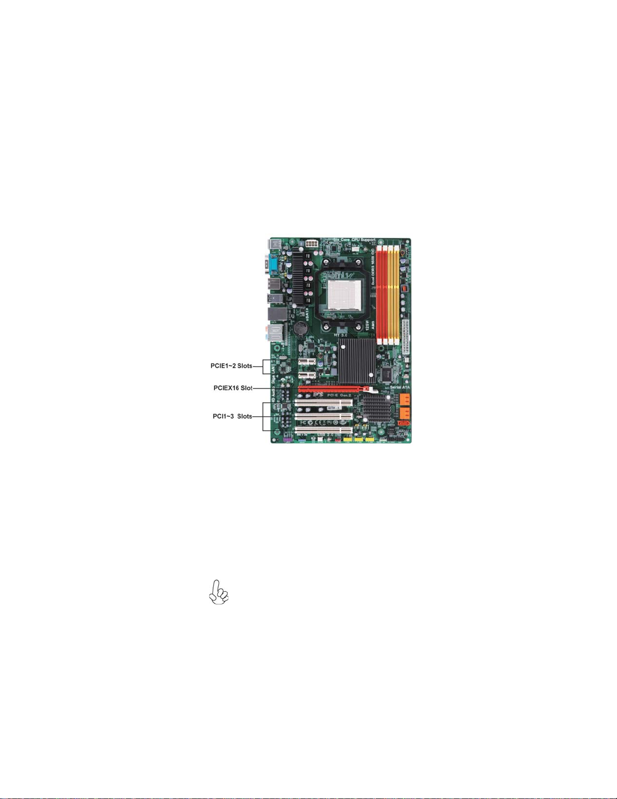
Expansion Slots
InstallingAdd-on Cards
The slots on this motherboard are designed to hold expansion cards and connect
them to the system bus. Expansion slots are a means of adding or enhancing the
motherboard’s features and capabilities. With these efficient facilities, you can in-
crease the motherboard’s capabilities by adding hardware that performs tasks that are
not part of the basic system.
PCI1~3 Slots This motherboard is equipped with three standard PCI slots.
PCI stands for Peripheral Component Interconnect and is a
bus standard for expansion cards, which for the most part, is
a supplement of the older ISA bus standard. The PCI slots on
this board are PCI v2.3 compliant.
The PCI Express x1 slots are fully compliant to the PCI
Express Gen2 (version 2.0).
PCIE1~2 Slots
Before installing an add-on card, check the documentation
for the card carefully. If the card is not Plug and Play, you
may have to manually configure the card before installa-
tion.
PCIEX16 Slot The PCI Express x16 slot is used to install an external PCI
Express graphics card that is fully compliant to the PCI
Express Gen2 (version 2.0).
16
InstallingtheMotherboard
Follow these instructions to install an add-on card:
1 Remove a blanking plate from the system case corresponding to the
slot you are going to use.
2 Install the edge connector of the add-on card into the expansion slot.
Ensure that the edge connector is correctly seated in the slot.
3 Secure the metal bracket of the card to the system case with a screw.
For some add-on cards, for example graphics adapters and network
adapters, you have to install drivers and software before you can begin
using the add-on card.
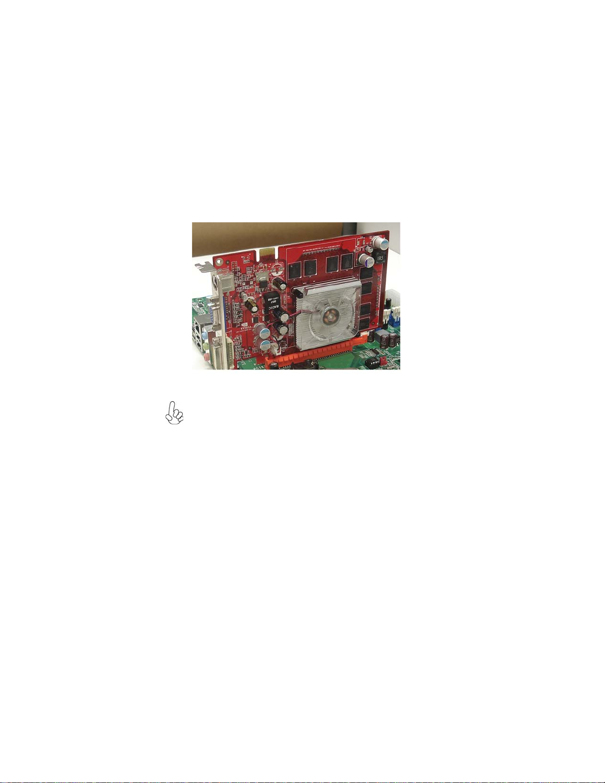
* For reference only
Table of contents
Other ECS Motherboard manuals


