ECS PF21 Extreme User manual


Table of Contents
CHAPTER 1
Introduction..............................................................................................1-1
Package Check List..................................................................................1-1
Feature Summary......................................................................................1-2
Special Features........................................................................................1-3
Major Components...................................................................................1-5
Headers and Connectors...........................................................................1-7
Jumpers.....................................................................................................1-13
Rear Panel................................................................................................1-14
CHAPTER 2
Installing the CPU & the CPU cooling fan................................................2-1
Installing Memory Module.......................................................................2-1
Connecting IDE, Floppy and SATA cable..................................................2-2
Installing Motherboard in a case...............................................................2-2
Connecting IDE, Floppy & SATA Device..................................................2-3
Installing Expansion cards........................................................................2-3
Connecting the Power supply cable...........................................................2-4
Powering up..............................................................................................2-4
CHAPTER 3
Entering the BIOS Setup Menu.................................................................3-1
Updating and Recovering the BIOS...........................................................3-1
Using AWARD Flash to update your BIOS..........................................3-1
Using ECS Top-Hat Flash to recover your BIOS..................................3-2
The Main Menu.......................................................................................3-2
Standard CMOS Features............................................................3-3
Advanced BIOS Features............................................................3-4
Advanced Chipset Features.........................................................3-7
Integrated Peripherals.................................................................3-9
Power Management Setup.................................................................3-13
PNP/PCI Configurations..................................................................3-15
PC Health Status............................................................................3-16

Frequency/Voltage Control................................................................3-17
Load Performance Defaults...............................................................3-19
Load Optimized Defaults..................................................................3-19
Set Supervisor/User Password...........................................................3-20
Save & Exit Setup...........................................................................3-20
Exit Without Saving.........................................................................3-20
CHAPTER 4
Software CD Information.........................................................................4-1
Running the Software CD.........................................................................4-1
Setup Tab..................................................................................................4-1
Application Tab........................................................................................4-2
Read Me Tab............................................................................................4-2
Software Utilities Introduction.................................................................4-2
Multi-Language Translations
Legal Notices
Chapter 1
This chapter entails the newest technology and rich
features on the Photon Extreme motherboard.

1.1 Introduction....................................................1-1
1.2 Package Check List...........................................1-1
1.3 Feature Summary...........................................1-2
1.4 Special Features.............................................1-3
1.5 Major Components........................................1-5
1.6 Headers and Connectors................................1-7
1.7 Jumpers........................................................1-13
1.8 Rear Panel...................................................1-14
Reference

1-1
1.1 Introduction
Thank you for choosing the ECS PF21 Extreme motherboard.
The PF21 Extreme is the next generation of high performance motherboard
designed to support the LGA775 socket Intel Pentiun4 Processors.
This motherboard has an ATX form factor that uses a 6-layer printed circuit
board and measures 305 mm x 244 mm.
The PF21 Extreme motherboard is based on the Intel 925XE Northbridge
and ICH6R chipsets to set a new benchmark for the best desktop platform
solution. Supporting up to 4 GB of system memory with DDR2 533/400
DDR DIMMs, high resolution graphics via PCI Expess ports, Dual LAN,
USB 2.0, 8-channel audio, Digital S/PDIF in/out, SATA support and
RAID function.
1.2 Package Check List
Motherboard User’s Guide Installation CD
Two Streamlined IDE &
FDD Ribbon Cable
USB+1394 PCI
Bracket & housing
Top Hat Flash I/O ShieldSATA Power Cable
Two SATA Cables Cross Over Cable
*Accessories are subject to change without prior notice.
1-2
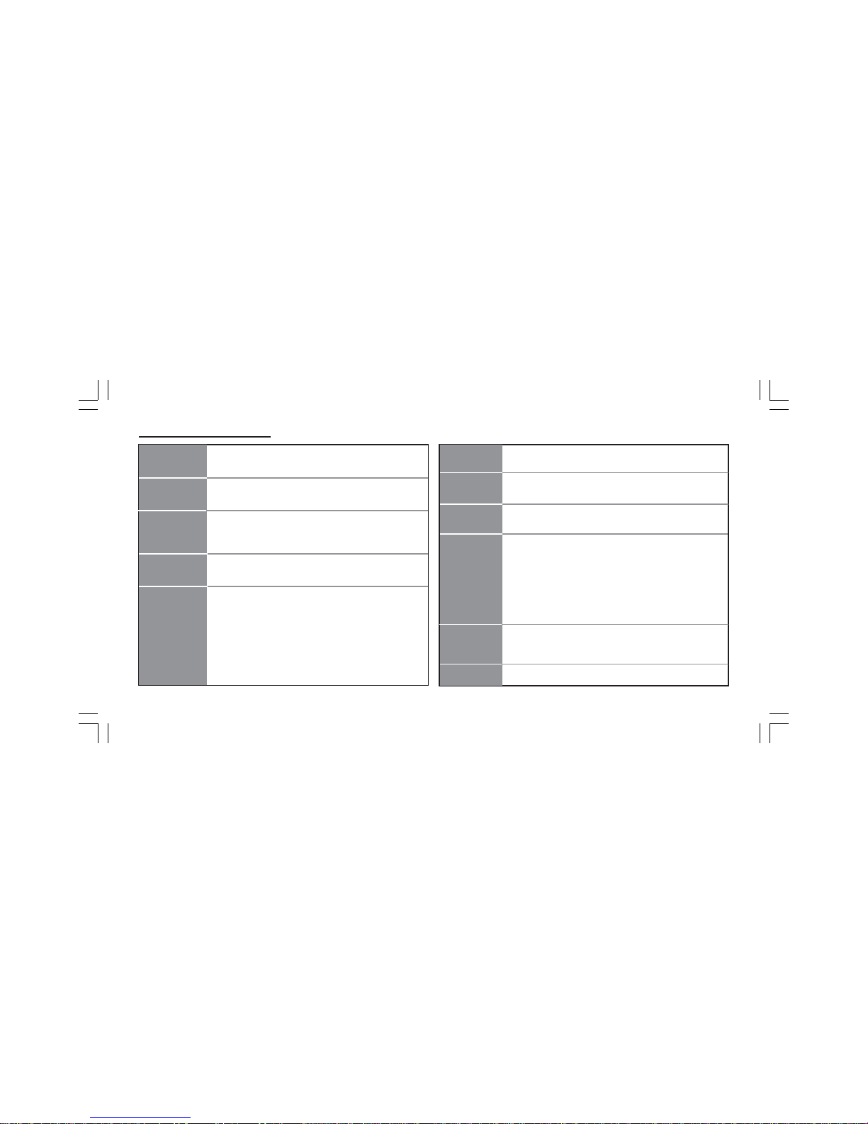
1.3 Feature Summary
CPU
Chipset • Intel 925XE & ICH6R
• North Bridge: Intel 925XE
• South Bridge: Intel ICH6R
Memory
Expansion
Slots
• 1 x PCI Express x16
• 2 x PCI Express x1
• 3 x PCI Slots
Storage • Supported by ICH6R
- 2 x Ultra DMA100/66 devices
- 4 x SATA devices,
- RAID 0 and RAID 1 configuration
• Supported by SiS180
- 2 x Ultra DMA133/100/66 devices
- 2 x SATA devices
- RAID 0, RAID 1, RAID 0+1 configuration
IEEE 1394a • VIA VT6307 IEEE1394a controller
• Supports 2 x IEEE1394a portrs
Audio • CMI9880 8-channel audio CODEC
• Compliant with Intel Azalia specification
Dual LAN • Marvel 88E8001 Gigabit LAN Controller
• Realtek8100C 10/100 Mbps Fast Ethernet Controller
Rear panel
I/O
• 1 x PS/2 keyboard connector
• 1 x PS/2 mouse connector
• 4 x USB ports
• 2 x RJ45 LAN connectors
• 1 x Serial port (COM1)
• 1 x Digital SPDIF out
• 1 x Digital SPDIF in
• Line-out/Line-in/Microphone in connectors
• LGA775 Socket for Intel Pentium 4 processor
• FSB 1066/800MHz (266/200MHz Core Clock)
• Supports Hyper-Threading Technology
• Dual-channel DDR memory architecture
• 4 x 240-pin DDR2 DIMM socket support up to 4 GB
• Supports DDR2 533/400
• Supports Non-ECC unbuffered 1.8V DDR DIMMs
BIOS features • Award BIOS with 4Mb Flash ROM
• Supports Plug and Play 1.0A, APM 1.2, Multi Boot, DMI
• Supports ACPI revision 1.0B specificaion
Internal I/O • 1 x 24-pin ATX Power Supply Connector & 4-pin 12 V
Connector

1-3
1.4 Special Features
Device plug with USB-like
ease!
Extreme PowerExtreme Power
Extreme PowerExtreme Power
Extreme Power
Upgrade your PC to
Server-grade power now!
Slash memory access time!
The best aluminum
capacitors empowering!
6-layer PCB!
Extreme GuardianExtreme Guardian
Extreme GuardianExtreme Guardian
Extreme Guardian
Auto restart after power
loss!
PC protection tool kit!
A ‘time machine’ to
protect and restore files!
• 1 x Floppy connector- supports 360K ~ 2.88M Bytes, 3
Mode FDDs or LS120
• 2 x IDE connectors
• 6 x Serial ATA connectors
• 2 x USB 2.0 headers support additional 4 USB ports
• 1 x 1394a header
• 1 x SMBus header
• 1 x Front panel switch/LED header
• 1 x Front panel audio header
• 1 x LPT header
• 1 x CHS1 header
• 1 x SMI1 header
• CD in header
• CPUFAN/NB_FAN/SYSFAN connectors
• ATX size
• 305mm x 244mm
Form Factor
Uncompromising DVD
audio quality!
One-key boot device
selection!
Awesome overclocking!
New generation of I/O
interface!

1-4
Become your own BIOS
‘doctor’!
Fuzzy logic design for
diagnosing PCI slots
health!
Memory module alert!
Extreme LinkExtreme Link
Extreme LinkExtreme Link
Extreme Link
Add peripherals and
consumer electronics
devices!
Keep best audio quality!
Let your PC as a
fileserver!
Server Class Dual LAN
for both Internet &
Intranet!
Flash BIOS from
Windows!
Rounded corners for
strength and safety!
PCI 2.3 support!
Smart LAN!
More port options!
All the USB 2.0
connectivity you’ll ever
need!
Industrial-strength LAN
power!
Auto-negotiate your 10/
100M LAN!
Let your PC as a
fileserver!
Eliminate data highway
roadblocks!
Ultra sound quality!
An dust-proof auto shutter
for optical connector!
Clear & Clean!
Extreme GeniusExtreme Genius
Extreme GeniusExtreme Genius
Extreme Genius
Color-coding for easy
connections!
More options for data
storage!
A cooling channel with a
fansink placed on top of
the PWM controller!
Cool operations, cool
appearance!
1-5
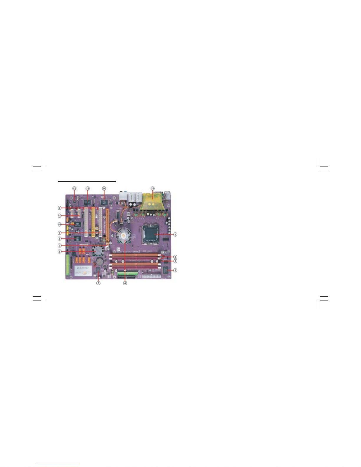
1.5 Major Components
1. CPU socket
LGA775 surface mount, Zero Insertion Force socket for latest Intel
Pentium 4 Processors support FSB 1066/800MHz (266/
200MHz Core Clock)
2. Dual-channel DDR2 DIMM sockets
These four 240-pin DIMM sockets support up to 4GB system
memory using unbuffered DDR2 533/400 DDR DIMMs.
3. Super I/O (83627THF) controller
The Winbond 83627THF Low Pin Count (LPC) interface
provides the commonly used super I/O functionality. The
chipset support a high performance floppy disk controller, a
multi-mode parallel port, one serial port, the mouse and keyboard
interface.
4. Northbridge controller
925XE is a Memory Controller Hub (MCH) designed for use with the
Pentium 4 processor in desktop platforms. It also supports
PCI Express specification.
5. Flash ROM
This 4Mb ROM contains the programmable BIOS program.
6. Southbridge controller
The Intel ICH6R integrated peripheral controller supports various I/O
functions including four Serial ATA connectors, dual channel Ultra
DMA100/66/33 master mode EIDE controller, up to eight USB

1-6
2.0 ports, Azalia Audio interface, and PCI 2.3 interface.
7. PCI Express x16 (PCI-E1) slot
This 925XE has one x16 PCI Express slot, which is intended for an
external PCI Express graphics card.
8. SiS 180 Serial ATA controller
This motherboard incorporates the high performance SiS 180 IDE
RAID controller, which supports RAID 0, RAID 1 and RAID 0+1
configuration.
9. PCI slots
These three 32-bit PCI 2.3 expansion slots support bus master PCI
cards like SCSI or LAN cards with 133MB/s maximum throughput.
10. IEEE 1394a controller
The IEEE 1394a controller provides high-speed and flexible
PC connectivity to a wide range of peripherals and devices compliant
to IEEE 1394a standards. The IEEE 1394a interface allows up to
400Mbps tranfer rates.
11. PCI Express x1 (PCI-E2/PCI-E3) slots
The two PCI Express x1 slots are fully compliant to the PCI Express
Base Specification revision 1.0a
12. Audio CODEC
The audio CODEC is compliant with Intel Azalia spec and supports
8-channel High Definition audio.
15. Cooling Accelerator
The cooling accelerator supercharges airflow exchange between the
chassis interior and exterior, keeping operating temperatures under
control.
a. Anti-Burn LED indicator
When this LED is light up, do not remove the memory module from
your DIMM slot or else your memory module will be damaged.
b. PCI LED indicator
The PCI LED indicates the PCI slot activity. These LEDs
will stop blinking when any add-on card has been installed. Blinking
means no add-on card installed or the add-on card was not properly
installed.
14. Gigabit LAN controller
The Gigabit LAN controller delivers transfer rates up to 10/100/
1000Mbps Ethernet connection. Ideal for handling large
amounts of data such as video, audio and voice.
13. 10/100Mbps LAN Controller
The 10/100Mbps LAN delivers a transfer rates up to 10/100 Mbps.
1-7
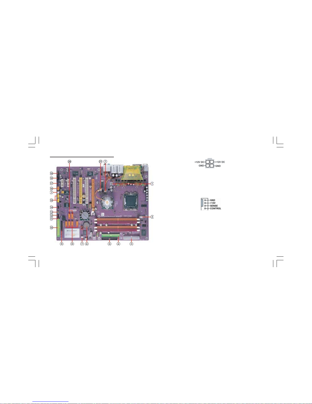
1.6 Headers and Connectors
1. ATX12V (ATX 12V Power Connector, 4 pin, White)
This connector supplies the CPU operation voltage (Vcore). Don’t
forget to connect the 4-pin ATX 12V connector, otherwise the
system cannot boot up.
2. CPU_FAN1 (CPU Fan Connector, 4 pin, White)
Please note that a proper installation of the CPU cooler is essential to
prevent the CPU from running under abnormal condition or damaged by
overheating. The fan connector supports the CPU cooling fan of
1.1A~2.2A (26.4W max.) at +12V.
1-8
AC power cord should only be connected to your power supply until
after ATX power cable and other related devices are firmly connected to
the motherboard. Make sure that your ATX12V power supply could
provide 8A of 12V and at least 1A on the +5V standby. The minimum
recommended power is 300W for a fully-configured system. If not, the
system may become unstable or may not even boot up.
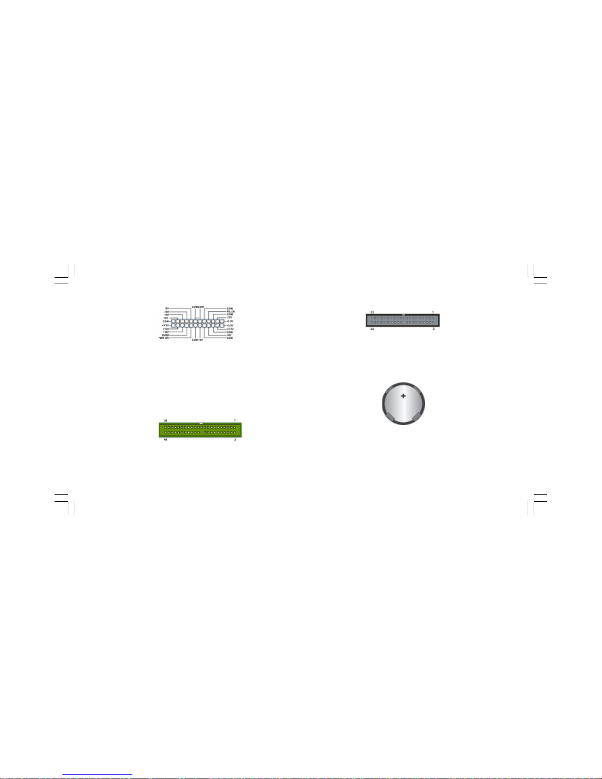
3. ATX1 (ATX PWR Connector, 24 pin, White)
IDE1 is supported by ICH6R South Bridge. Please connect the first hard
disk to IDE 1. The streamline IDE cable must be the same side with the
Pin 1.
4. IDE1 (IDE1 Connector, 40-1 pin, Green)
6. Battery
Danger of explosion if battery is incorrectly replaced. Replace only with
the same of equivalent type recommended by the manufacturer.
5. FDD1 (Floppy Connector, 34-1 pin, Black)
Please connect the floppy drive ribbon cables to FDD. It supports
360K, 12M, 720K, 1.44M and 2.88M bytes floppy disk types.

1-9
7. SYSFAN1/SYSFAN2/SYSFAN3(System Fan Connectors, 3 pin,
White)
If you installed wrong direction, the chip fan will not work. Sometimes
will damage the chip fan.
8. SATA1/2/3/4 (Serial ATA Connectors, 7 pin, Orange)
These next generation connectors are delivered by ICH6R South Bridge
support the thin Serial ATA cables for Serial ATA hard disks. The
current Serial ATA interface allows up to 150MB/s data transfer rate,
faster than the standard parallel ATA with 133MB/s (UltraATA 133)
10. IDE2 (IDE2 Connector/IDE RAID ATA133 Connector, 40-1
pin, Green)
This is supported by SiS180. The streamline IDE cable must be the same
side with the Pin 1. This connector supports either RAID 0 or RAID 1
configuration through the onboard SiS180 controller. You can connect
two UltraATA 133 hard disks to this connector and set up a disk array
configuration. You may also set up the UltraATA 133 hard disks with
the Serial ATA hard disks on the Serial ATA RAID connectors to create
a multi-RAID configuration.
9. LPT1 (Onboard LPT Port, 26-1 pin, Black)
This 25-pin port connects a parallel printer, a scanner, or other
devices.
Note
: To install the OS, the CD-ROM must be installed on IDE1. You
may as well connect the CD-ROM to IDE2, only after SiS180 driver is
installed before you start using it!

1-10
11. CHS1 (Chassis Intrusion Detect Header, 2 pin, Black)
This header allows users to detect unauthorized intrusion to the case.
It will alert users with a warning message when the case is turned on.
12. SMI1 (System Management Interrupt Header, 2 pin, Black)
This connector is for use with SMI hardware interrupt power
management.
13. PANEL1 (Front Panel Switch/LED Header, 10-1 pin)
The front panel connector provides a standard set of switch and LED
connectors commonly found on ATX or micro-ATX cases.
The motherboard supports an infrared (IR1) data port. Infrared
ports allow the wireless exchange of information between your
computer and similarly equipped devices such as printers, laptops,
Personal Digital Assistants (PDAs), and other computers.
14. IR1 (Infrared Header, 6-1 pin, Black)
1-11
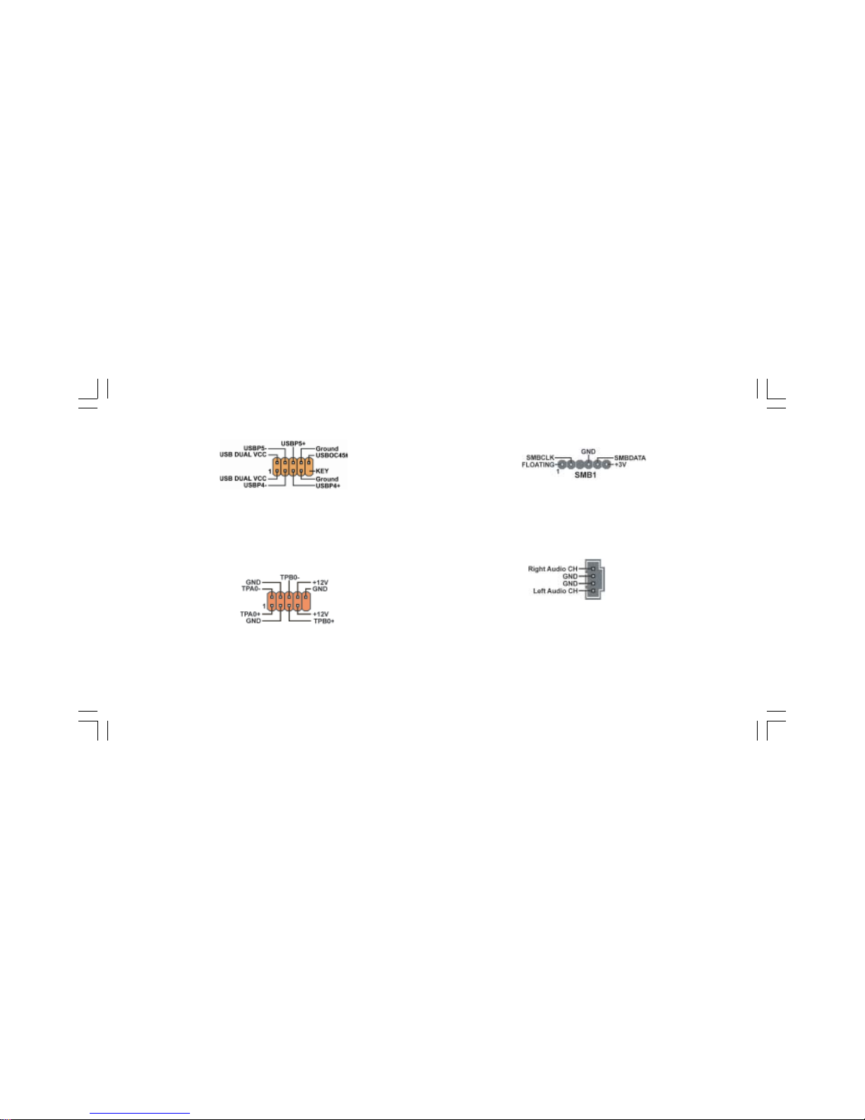
15. USB3/USB4 (Front USB Headers, 10-1 pin, Yellow)
If the USB ports on the rear panel are inadequate, two USB headers are
available for additional USB ports. The USB header complies with USB
2.0 specification that supports up to 480 Mbps connection speed. This
speed advantage over the conventional 12 Mbps on USB 1.1.
16. 1394A2 (IEEE 1394a Header, 10-1 pin, Orange)
Attach the 10-1 pin 1394 cable plug from the device to this connector.
You may also connect a 1394-compliant internal hard disk to this con-
nector.
17. SMB1 (SMBus Header, 6-1 pin, Black)
This connector allows you to connect SMBus (System Management Bus)
devices. Devices communicate with an SMBus host and/or other SMBus
devices using the SMBus interface.
18. CDIN1 (CD In Connector, 4 pin, Black)
Connect CD-ROM or DVD-ROM audio out to the connector.
1-12
If you installed wrong direction, the chip fan will not work. Sometimes
will damage the chip fan.
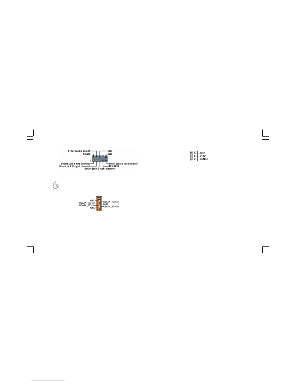
21. NBFAN1 (Northbridge Fan Connector, 3 pin, White)
20. SATA5/6 (Serial ATA RAID Connectors, 7 pin, Orange)
These Serial ATA connectors support SATA hard disks that you may
configure as a RAID set. Through the onboard SiS180 RAID controller
you may create a RAID 0, RAID 1, RAID 0+1, or multiRAID configu-
ration together with the RAID ATA133 connector.
This is an interface for the Intel front panel audio cable that allows
convenient connection and control of audio devices.
19. AUDIO1 (Front Panel Audio Header, 10-1 pin, Purple)
If your front panel cable is seperated, please connect it to pin1
and pin3 or pin5 and pin7 to activate the MIC function.
1-13
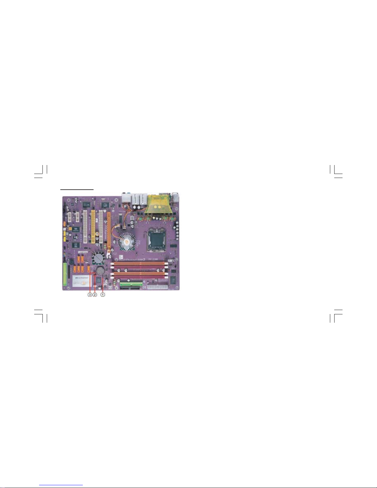
1.7 Jumpers
2. JP1 (Clear CMOS)
This jumper allows you to clear the Real Time Clock (RTC) RAM in
CMOS. You can clear the CMOS memory of date, time, and system
setup parameters by erasing the CMOS RAM data. Before
clearing the CMOS data, make sure to turn the system off.
1. BIOS_WP1 (Flash Protect)
This jumper enables you to prevent the BIOS from being updated
(flashed).
Open: Disable (Default)
Short: Enable
3. JP10 (Clear RTC) (Optional)
This jumper allows you to clear the Real Time Clock (RTC) RAM in
CMOS.

1-14
1. PS/2 mouse port
This 6-pin connector is for connecting PS/2 mouse.
2. RJ-45 port
This port allows connection to a Local Area Network (LAN)
through a network hub. It supports up to 10/100Mbps transfer rate.
3. RJ-45 port
This port allows connection to a Local Area Network (LAN)
through a network hub. It supports up to Gigabit tranfer rate.
4. Side Surround Jack *
This jack connects a tape player or other audio sources. In 8-channel
mode, the function of this jack is Side Surround speaker out.
5. Back Surround Jack
*
This jack connects a tape player or other audio sources. In 8-channel
mode, the function of this jack is Back-Surround speaker out.
1.8 Rear Panel
6. Center/Bass Jack *
This jack connects a tape player or other audio sources. In 8-channel
mode, the function of this jack is Center/Bass speaker out.
7. Front Out Jack *
This jack connects a tape player or other audio sources. In 8-channel
mode, the function of this jack is Front speaker out.
8. Optical S/PDIF output port
This jack connects to external digital audio output devices.
9. Microphone in Jack *
The function of the jack is microphone input.
10/11. USB 2.0 ports 3/4
These Universal Serial Bus (USB) ports are available for connecting
USB 2.0 devices.
12. 1394_A1 port
Use the 1394a port to connect any Firewire device.
13. S/PDIF input port
This jack connects to external digital audio input devices.
14. Serial port
This 9-pin COM1 port is for serial devices.
15. PS/2 keyboard port
This 6-pin connector is for connecting PS/2 keyboard.
The audio ports with a * sign can be changed to audio input or
audio output by changing the driver utility setting.

Chapter 2
This chapter explains the hardware setup procedure
for this motherboard, such as installing the CPU,
memory modules, expansion cards, as well as the
jumpers.
Table of contents
Other ECS Motherboard manuals


