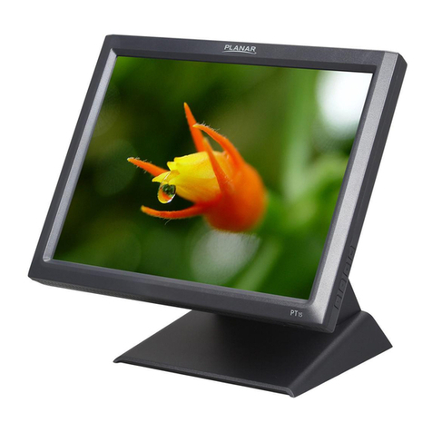
EDA ED-HMI2120-101C User manual

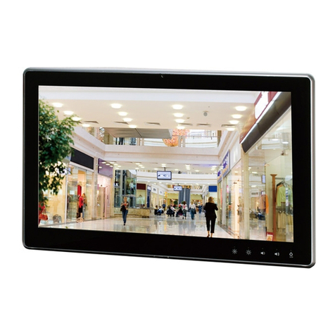
ED-HMI2120-101C
10.1 inch High Reliability Industrial
Panel PC Based on Raspberry Pi
CM4
User Manual
EDA Technology Co., LTD
August 2023

Contact Us
Thank you very much for purchasing and using our products, and we will serve
you wholeheartedly.
As one of the global design partners of Raspberry Pi, we are committed to
providing hardware solutions for IOT, industrial control, automation, green
energy and artificial intelligence based on Raspberry Pi technology platform.
You can contact us in the following ways:
EDA Technology Co.,LTD
Address:Room 301, Building 24, No.1661 Jialuo Road, Jiading District,
Shanghai
Mail: [email protected]
Phone: +86-18217351262
Website: https://www.edatec.cn
Technical Support:
Mail: [email protected]
Phone: +86-18627838895
Wechat: zzw_1998-

Copyright Statement
ED-HMI2120-101C and its related intellectual property rights are owned by EDA
Technology Co.,LTD.
EDA Technology Co.,LTD owns the copyright of this document and reserves all
rights. Without the written permission of EDA Technology Co.,LTD, no part of
this document may be modified, distributed or copied in any way or form.

Disclaimer
EDA Technology Co.,LTD does not guarantee that the information in this manual
is up to date, correct, complete or of high quality. EDA Technology Co.,LTD also
does not guarantee the further use of this information. If the material or non-
material related losses are caused by using or not using the information in this
manual, or by using incorrect or incomplete information, as long as it is not
proved that it is the intention or negligence of EDA Technology Co.,LTD, the
liability claim for EDA Technology Co.,LTD can be exempted. EDA Technology
Co.,LTD expressly reserves the right to modify or supplement the contents or
part of this manual without special notice.

i
Foreword
Related Manuals
All kinds of product documents contained in the product are shown in the following table, and users can
choose to view the corresponding documents according to their needs.
Documents Instruction
ED-HMI2120-101C Datasheet
This document introduces the product features, software and
hardware specifications, dimensions and ordering code of
ED-HMI2120-101C to help users understand the overall system
parameters of the products.
ED-HMI2120-101C User Manual
This document introduces the appearance, installation, startup
and configuration of ED-HMI2120-101C to help users use the
product better.
ED-HMI2120-101C Application Guide
This document introduces the OS download, eMMC flashing and
partial configuration of ED-HMI2120-101C to help users use the
product better.
Users can visit the following website for more information:
https://www.edatec.cn
Reader Scope
This manual is applicable to the following readers:
Mechanical Engineer
Electrical Engineer
Software Engineer
System Engineer

ii
Related Agreement
Terminology Convention
Terminology Meaning
CM4 Raspberry Pi CM4 Module, Full name is Compute Module 4
Symbolic Convention
Symbolic Instruction
Prompt symbols, indicating important features or operations.
Notice symbols, which may cause personal injury, system damage, or signal interruption/loss.
May cause great harm to people.

iii
Safety Instructions
This product should be used in an environment that meets the requirements
of design specifications, otherwise it may cause failure, and functional
abnormality or component damage caused by non-compliance with relevant
regulations are not within the product quality assurance scope.
Our company will not bear any legal responsibility for personal safety
accidents and property losses caused by illegal operation of products.
Please do not modify the equipment without permission, which may cause
equipment failure.
When installing equipment, it is necessary to fix the equipment to prevent it
from falling.
If the equipment is equipped with an antenna, please keep a distance of at
least 20cm from the equipment during use.
Do not use liquid cleaning equipment, and keep away from liquids and
flammable materials.
This product is only supported for indoor use.

Content
Foreword .....................................................................................................................................................i
Related Manuals ..................................................................................................................................i
Reader Scope ......................................................................................................................................i
Related Agreement .............................................................................................................................ii
Terminology Convention...............................................................................................................ii
Symbolic Convention ...................................................................................................................ii
Safety Instructions..................................................................................................................................... iii
1Product Description......................................................................................................................... 1-1
1.1 Overview........................................................................................................................... 1-2
1.2 Packing List ...................................................................................................................... 1-3
1.3 Appearance ...................................................................................................................... 1-4
1.3.1 Front Panel ................................................................................................................ 1-4
1.3.2 Rear Panel................................................................................................................. 1-5
1.3.3 Side Panel ................................................................................................................. 1-5
1.4 Button ............................................................................................................................... 1-8
1.5 Indicator ............................................................................................................................ 1-9
1.6 Interface.......................................................................................................................... 1-10
1.6.1 Card Slot.................................................................................................................. 1-10
1.6.2 Power Supply Interface............................................................................................ 1-10
1.6.3 Audio Interface..........................................................................................................1-11
1.6.4 RS485/RS232 Interface............................................................................................1-11
1.6.5 1000M Ethernet Interface ........................................................................................ 1-13
1.6.6 100M Ethernet Interface .......................................................................................... 1-14
1.6.7 HDMI Interface......................................................................................................... 1-14
1.6.8 USB 2.0 Interface .................................................................................................... 1-15
1.6.9 Micro USB Interface................................................................................................. 1-15
1.6.10 Antenna Interface .................................................................................................... 1-15
2Installing Components..................................................................................................................... 2-1
2.1 Installing Antenna (optional).............................................................................................. 2-2
2.2 Installing Micro SD Card ................................................................................................... 2-3
2.3 Installing Nano SIM Card (optional) .................................................................................. 2-4
3Installing Device .............................................................................................................................. 3-1
3.1 Embedded Installation ...................................................................................................... 3-2
4Booting The Device......................................................................................................................... 4-1
4.1 Connecting Cables............................................................................................................ 4-2
4.2 Booting The System For The First Time............................................................................ 4-3
4.2.1 Raspberry Pi OS (Desktop) ....................................................................................... 4-3
4.2.2 Raspberry Pi OS (Lite)............................................................................................... 4-3
5Configuring System......................................................................................................................... 5-1
5.1 Finding Device IP.............................................................................................................. 5-2
5.1.1 Query IP by Using ifconfig Command........................................................................ 5-2
5.1.2 Login Router to Query IP ........................................................................................... 5-2

5.1.3 Scan For Using NMAP Tool ....................................................................................... 5-3
5.2 Remote Login ................................................................................................................... 5-5
5.2.1 Connecting To The Device Via SSH .......................................................................... 5-5
5.2.2 Connecting To The Device Desktop Through VNC .................................................... 5-7
5.3 Configuring Storage Devices .......................................................................................... 5-10
5.3.1 Mounting a Storage Device ..................................................................................... 5-10
5.3.2 Unmounting The Storage Device............................................................................. 5-12
5.3.3 Set The Storage Device To Mount Automatically ..................................................... 5-12
5.4 Configuring Ethernet IP................................................................................................... 5-14
5.4.1 Configuring IP by Using The NetworkManager Tool ................................................ 5-14
5.4.2 Configuring IP by Using The dhcpcd Tool ................................................................ 5-17
5.5 Configuring WiFi (Optional)............................................................................................. 5-19
5.5.1 Enabling WiFi Function............................................................................................ 5-19
5.5.2 Using The NetworkManager Tool To Configure WiFi Connections........................... 5-21
5.5.3 Configuring WiFi Connection By Using dhcpcd Tool................................................ 5-23
5.6 Configuring Bluetooth (optional) ..................................................................................... 5-25
5.6.1 Basic Configuration Command ................................................................................ 5-25
5.6.2 Configuration Example ............................................................................................ 5-25
5.7 Configuring 4G (Optional) ............................................................................................... 5-27
5.7.1 Using The NetworkManager Tool To Configure The Network .................................. 5-27
5.7.2 Configuring The Network By Using The dhcpcd Tool............................................... 5-28
5.7.3 Configuring 4G Module Reset.................................................................................. 5-29
5.8 Configuring Buzzer ......................................................................................................... 5-31
5.9 Configuring RTC ............................................................................................................. 5-32
5.10 Configuring Serial Port.................................................................................................... 5-33
5.10.1 Installing picocom tool ............................................................................................. 5-33
5.10.2 Configuring RS232 .................................................................................................. 5-33
5.10.3 Configuring RS485 .................................................................................................. 5-33
5.11 Configuring Audio............................................................................................................ 5-35
5.11.1 Adjusting The Volume.............................................................................................. 5-35
5.11.2 Configuring Record.................................................................................................. 5-37
5.12 Configuring USER Indicator............................................................................................ 5-39
5.13 Configuring LCD Screen ................................................................................................. 5-40
5.13.1 Rotating Orientation................................................................................................. 5-40
5.13.2 Adjusting Brightness ................................................................................................ 5-41
5.14 Configuring Camera........................................................................................................ 5-43

1 Product Description
ED-HMI2120-101C User Manual 1-2
1.1 Overview
ED-HMI2120-101C is a high reliability industrial Panel PC based on Raspberry Pi CM4. According to
different application scenarios and user needs, different specifications of RAM and eMMC computer
systems can be selected.
RAM can choose 1GB、2GB、4GB and 8GB
eMMC can choose 8GB、16GB and 32GB
ED-HMI2120-101C provides common interfaces such as HDMI, USB, Ethernet, RS232 and RS485,
and supports access to the network through Wi-Fi, Ethernet and 4G. The integration of super capacitor
(backup power supply), RTC, Watch Dog, EEPROM and encryption chip provides the ease of use and
reliability of the product, which is mainly used in industrial control and IOT.

1 Product Description
ED-HMI2120-101C User Manual 1-3
1.2 Packing List
1x ED-HMI2120-101C Unit
4 x buckles(including 4xM4*8 screws and 4xM4*16 screws)
[option WiFi/BT version]1x 2.4GHz/5GHz WiFi/BT Antenna
[option 4G version]1x 4G/LTE Antenna

1 Product Description
ED-HMI2120-101C User Manual 1-4
1.3 Appearance
Introducing the functions and definitions of interfaces on each panel.
1.3.1 Front Panel
This section introduces types and definitions of the front panel interface.
NO. Function Definition
1 1 x LCD display, 10.1 inch LCD, which supports up to 1280x800 and multi-point
capacitive touchscreen.
2 1 x camera, 800M front camera.

1 Product Description
ED-HMI2120-101C User Manual 1-5
1.3.2 Rear Panel
This section introduces types and definitions of the rear panel interface.
NO. Function Definition
1
5 x installation holes of buckle, which are used to fix the buckles to the device for
installation. You only need to use 4 installation holes during installation, and reserve
one as a spare.
1.3.3 Side Panel
This section introduces types and definitions of the side panel interfaces.

1 Product Description
ED-HMI2120-101C User Manual 1-6

1 Product Description
ED-HMI2120-101C User Manual 1-7
NO. Function Definition
1 1 x WiFi/BT antenna port, SMA connector, which is used to connect Wi-Fi/BT
antenna.
2 1 x 4G antenna port, SMA connector, which is used to connect 4G antenna.
3 1 x Micro USB port, which supports to flash eMMC for the system.
4 1 x Nano SIM slot, using to install a SIM card for acquiring 4G signals.
5 1 x Micro-SD card slot, which supports the installation of SD card for storing user
data.
6 1 x Reset button, hidden button, you can press the button to restart the device.
7 2 x USB 2.0 ports, type A connector, each channel supports up to 480Mbps.
8 1 x HDMI port, type A connector, which compatibles with HDMI2.1 standard and
supports 4K 60Hz. It supports to connect a display.
9 1 x 10/100M adaptive ethernet port, RJ45 connector, with led indicator. It can be
used to access the network.
10 1 x 10/100/1000M adaptive ethernet port, RJ45 connector, with led indicator. It can
be used to access the network. PoE can be supported through expansion module.
11 2 x RS485 ports, 6-Pin 3.5mm spacing phoenix terminal, which is used to connect
the third-party control equipment.
12 2 x RS232 ports, 6-Pin 3.5mm spacing phoenix terminals, which is used to connect
third-party control equipment.
13
1 x Audio input/Stereo output, 3.5mm audio jack connector. It can be used as MIC
IN and LINE OUT.
When a headphone is connected, the audio output is switched to the
headphone.
When a headphone is not connected, the audio output is switched to the
speaker.
14 1 x DC input, 2-Pin 3.5mm spacing phoenix terminals with screw holes. It supports
9V~36V input, and the signal is defined as VIN+/GND.
15 4 x green UART indicators, using to check the communication status of UART port.
16 1 x green 4G indicator, using to check the status of 4G signal.
17 1 x red power indicator, using to check the status of device power-on and power-off.
18 1 x green system status indicator, using to check the working status of device.
19 1 x green user indicator, user can customize a status according to actual
application.

1 Product Description
ED-HMI2120-101C User Manual 1-8
1.4 Button
ED-HMI2120-101C includes a RESET button, which is a hidden button, and the silkscreen on the
case is "RESET". The RESET button is connected with the Global_EN pin of CM4 chip.
When the Global_EN pin is high level, it means that CM4 has been started;
When the Global_EN pin is low level, the CM4 will be reset.
Pressing the RESET button will pull the Global_EN pin low and reset the device.

1 Product Description
ED-HMI2120-101C User Manual 1-9
1.5 Indicator
This section introduces various statuses and meanings of indicators contained in ED-HMI2120-101C.
Indicator Status Description
PWR
On The device has been powered on.
Blink Power supply of the device is abnormal, please
stop the power supply
immediately.
Off The device is not powered on.
ACT Blink The system started successfully and is reading and writing data.
Off The device is not powered on or does not read and write data.
USER
On User can customize a status according to actual application.
Off The device is not powered on or not defined by the user, and the default status
is off.
4G On The dial-up is successful and the connection is normal.
Off 4G signal is not connected or the device is not powered on.
Yellow indicator
of Ethernet port
On The data transmission is abnormal.
Blink Data is being transmitted over the Ethernet port
Off The Ethernet connection is not set up.
Green indicator
of Ethernet port
On The Ethernet connection is in the normal state.
Blink The Ethernet connection is abnormal.
Off The Ethernet connection is not set up.
COM1~COM4 On/Blink Data is being transmitted.
Off The device is not powered on or there is no data transmission.

1 Product Description
ED-HMI2120-101C User Manual 1-10
1.6 Interface
Introducing the definition and function of each interface in the product.
1.6.1 Card Slot
ED-HMI2120-101C includes an SD card slot and a Nano SIM card slot.
1.6.1.1 SD Card Slot
The silkscreen on the case of Micro SD card slot is " ", which is used to install SD card for storing
user data.
1.6.1.2 SIM Card Slot
The silkscreen on the case of Nano SIM card slot is " ", which is used to install SIM card for obtaining
4G signals.
The size differences between standard SIM, Micro SIM and Nano SIM cards are as follows:
1.6.2 Power Supply Interface
The ED-HMI2120-101C includes one power input, the silkscreen of port is "VIN+/GND", the connector
model is DEGSON 15EDGRM-3.5-02P-1Y-00A(H), the terminal spacing is 3.5mm, and the pins are
defined as follows.

1 Product Description
ED-HMI2120-101C User Manual 1-11
Pin ID Pin Name
1 GND
2 9V~36V
1.6.3 Audio Interface
ED-HMI2120-101C includes one audio input, the silkscreen of port is " ", the connector model is
MTCONN MTEP83-20600B-22299, and the connector is a 3.5mm three-stage headphone jack, which
supports OMTP stereo headphone output and mono microphone recording.
When the headphone is connected, the audio output is switched to the headphone.
When the headphone is not connected, the audio output is switched to the speaker.
1.6.4 RS485/RS232 Interface
ED-HMI2120-101C includes 2 RS485 ports and 2 RS232 ports. The silkscreen of single RS485 is
"IGND/A/B" and the silkscreen of single RS232 is "IGND/TX/RX". The connector model is
DEGSON15EDGRHC-THR-3.5-06P-13-00A (h), and the terminal spacing is 3.5mm.
Pin Definition
Terminal pins are defined as follows:
Table of contents

