eDAQ e-corder User manual

e-corder®www.eDAQ.com
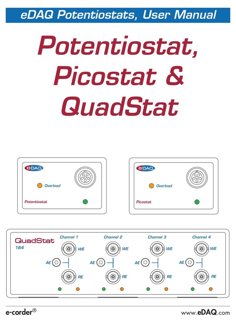
eDAQ Modular Potentiostats
Potentiostat,
Dual Picostat
& QuadStat
WE WE WE WE
QuadStat
RE RE RE RE
AE AE AE AE
Channel 1 Channel 2 Channel 3 Channel 4
164
Potentiostat
Overload
Dual PicoStat
362
Status
Power
Trigger
Overload Overload
Channel 1 Channel 2

ii eDAQ Potentiostats
This document was, as far as possible, accurate at
the time of printing. Changes may have been made
to the software and hardware it describes since
then: eDAQ Pty Ltd reserves the right to alter
specifications as required. Late-breaking information
may be supplied separately. Latest information and
information and software updates can be obtained
from our web site.
Trademarks of eDAQ
e-corder and PowerChrom are registered
trademarks of eDAQ Pty Ltd. Specific model
names, such as e-corder 210, PowerChrom
280, Dual Picostat, Picostat, QuadStat, and
isoPod, are trademarks of eDAQ Pty Ltd. Chart
and Scope are trademarks of ADInstruments
Pty Ltd and are used under license by eDAQ.
EChem is a trademark of eDAQ Pty Ltd.
Other Trademarks
Windows XP, Vista, and Windows 7 are trademarks
of Microsoft Corporation.
PostScript, and Acrobat are registered trademarks of
Adobe Systems, Incorporated.
All other trademarks are the properties of their
respective owners.
Products: Potentiostat (EA161)
Potentiostat (EA163)
Dual Picostat (EA362)
QuadStat (EA164)
Document Number: UM-EA161/3/4/362-1212
Copyright © December 2012
eDAQ Pty Ltd
6 Doig Avenue
Denistone East, NSW 2112
Australia
http://www.eDAQ.com
email: [email protected]
All rights reserved. No part of this document may be
reproduced by any means without the prior written
permission of eDAQ Pty Ltd.

eDAQ Potentiostats iii
Contents
1 Overview 1
How to Use this Manual 2
eDAQ Modular Potentiostats 2
Checking the unit 2
2 The Potentiostat 3
The Front Panel 4
The Electrode Connector 4
Electrode Cable 5
The Online Indicator 6
The Overload Indicator 6
The Back Panel 7
E Out, I Out and E In Connectors 8
I2C Connectors 8
Grounding Connector 8
Connecting the Potentiostat 9
First Use 11
Potentiostat Control Window 13
Maintenance 20
3 The Dual Picostat 21
The Front Panel 22
Electrode Connectors 22
Electrode Cable 23
The Power Indicator 23
The Status Indicator 24
The Overload Indicator 24
The Back Panel 25
Power Connector, On/Off 25
E Out, I Out and E In Connectors 25
USB socket 26
I2C Connectors 26
Grounding Connector 26
Connecting the Dual Picostat 27
First Use 30
Dual Picostat Control Window 30
Maintenance 37
4 The QuadStat 39
The Front Panel 40
Electrode Connectors 40
Electrode Cables 40
The Online Indicators 41
The Overload Indicators 41
The Back Panel 43
E Out, I Out and E In Connectors 43
I2C Connectors 43
Grounding Connector 44
Connecting the QuadStat 46
Using a Common Reference and Auxiliary
49
Using Multiple References and Auxiliaries
50

iv eDAQ Potentiostats
First Use 50
QuadStat Control Window 51
QuadStat Potential Window 56
Maintenance 57
5 Techniques 59
Introduction 60
Linear Scan Techniques 61
Fast Cyclic (or Linear Sweep) Voltammetry
61
Chronoamperometry with Chart 62
Chronoamperometry with Scope 64
Chronocoulometry 65
Chronopotentiometry 67
Chart software 69
Controlled Potential Electrolysis 70
Controlled Current Electrolysis 71
Amperometric Sensors 72
Biosensors 73
Microdialysis Sensor 73
Dissolved Oxygen (dO2) Sensors 74
Nitric Oxide (NO) Sensors 75
A Technical Aspects 77
Potentiostat 77
Dual Picostat 79
QuadStat 81
B Troubleshooting 85
C Specifications 91
Potentiostat 91
Dual Picostat 94
QuadStat 96
D Electrochemical Equations 99
Linear Sweep and Cyclic Voltammetry 99
Chronoamperometry 101
Chronocoulometry 102
License & Warranty 107

eDAQ Potentiostats 1
CHAPTER ONE
1Overview
There are three eDAQ modular potentiostats:
• Potentiostat (EA163), Chapter 2. Single channel, three electrode
potentiostat/galvanostat with gain ranges of 20 nA to 100 mA;
• Dual Picostat (EA362), Chapter 3. Two channel, three electrode,
high sensitivity potentiostat with gain ranges of 2 pA to 10 μA; and
• QuadStat (EA164), Chapter 4. Four channel, three electrode
potentiostat with gain ranges of 200 pA to 10 mA.
They are designed for use with an e-corder®system.
Some of the uses of the Potentiostat, Picostat, and QuadStat, are
mentioned in Chapter 5, and also in the EChem Software Manual
which describes the use of the optional EChem software.
NOTE
This manual is for the
EA163 Potentiostat,
EA362 Dual Picostat, and
EA164 QuadStat. If you
have an older model
EA160 or EA161
Potentiostat, or EA162
Picostat then please ask
us to send you the
appropriate manual.

2eDAQ Potentiostats
How to Use this Manual
This manual describes how to set up and begin using your Potentiostat
(Chapter 2), Dual Picostat (Chapter 3), or QuadStat (Chapter 4). Their
use with Chart and Scope software is also described (Chapter 5).
The appendices provide technical and trouble shooting information.
See the EChem Software Manual for a description of the use of these
potentiostats with the optional EChem software.
eDAQ Modular Potentiostats
The Potentiostat, Dual Picostat and QuadStat are modular units and
must be used with an e-corder data recording system.
They can performing various voltammetric and amperometric
experiments under full software control and are automatically
recognised by the Chart, Scope or EChem software which control their
gain range, signal filtering, and other settings.
See our web site at www.eDAQ.com for more information.
Checking the unit
Before you begin working with your Potentiostat, Dual Picostat, or
QuadStat please check that:
• all items described in the packing list are included; and that
• there are no signs of damage that may have occurred during
transit.
Contact your eDAQ distributor if you encounter a problem.
You should also become familiar with the basic features of your e-corder
system, which are discussed in the e-corder Manual which will be
placed as a pdf file on your computer hard disk when you install the
software.

eDAQ Potentiostats 3
CHAPTER TWO
2The Potentiostat
This chapter describes how to connect and use your model EA163
Potentiostat. If you have an older model EA160 or EA161 Potentiostat
please refer to the documentation that came with your unit or contact
IMPORTANT: Always make sure that the e-corder is turned off before you
connect or disconnect the Potentiostat. Failure to do this may result in
damage to the e-corder and/or the Potentiostat.
NEW FEATURES: If you have used the older EA161 Potentiostat then you
will notice it is very similar to the new EA163 Potentiostat which has
higher bandwidth (100 kHz) and so is more suitable for
electrochemical impedance spectroscopy (EIS).

4eDAQ Potentiostats
The Front Panel
The front panel of the Potentiostat is shown in Figure 2–1.
The Electrode Connector
The electrode connector of the Potentiostat provides connection pins for
the Working, Auxiliary and Reference electrode lead wires. The
connector also provides connections for the lead shields which protect
the signals in the cable wiring from electrical interference (noise
pickup).
The pin assignments of the Potentiostat electrode connector are shown
in Figure 2–2. The Auxiliary and Reference electrode leads have
Potentiostat
Overload
Overload
indicator light
Electrode connector,
Lemo socket,
to electrodes
Online indicator light
Working Electrode Auxiliary Electrode
Reference Electrode Shield
Reference Electrode
Working Electrode Shield Not connected
Alignment dot
Figure 2–1
The Potentiostat front
panel.
Figure 2–2
The Potentiostat electrode
connector as seen when
looking at the front
panel.

Chapter 2 — The Potentiostat 5
coaxial shields which are maintained at the respective electrode
potential.
Electrode Cable
The Potentiostat is supplied with an electrode cable comprising three
leads, with each lead terminated by an alligator clip. The Reference
and Working electrode leads are shielded to protect the signals from
external interference. The alligator clips allow connection to a wide
variety of electrodes, and the leads are color–coded to indicate the
type of electrode to which they should be attached (Table 2–1).
For normal three–electrode potentiostat, page 13, or galvanostat,
page 14, use, the reference electrode must never be connected to
either the auxiliary (red) or working (green) leads, otherwise the current
that would be passed through the electrode could effectively destroy it
as a reference potential source.
When two–electrode potentiostat, or galvanostat, operation is required
the auxiliary and reference leads (red and yellow) should be attached
to the single ‘counter electrode’. The green lead is attached to the
working electrode.
When using in ZRA (zero resistance ammeter) mode, connect the
working (green) and auxiliary (red) leads to the two electrodes (or
circuit test points) across which to measure the current, page 14. The
reference lead (yellow) can be connected to a reference electrode (or
circuit test point) to measure the potential difference to the auxiliary
(and working) leads.
When using High Z (high impedance) mode, connect the working
(green) lead to one electrode and the reference lead (yellow) lead to a
reference electrode to measure the potential difference between the
leads, page 14. On the EA163 Potentiostat the auxiliary electrode lead
To ensure good grip, the
electrode cable alligator
clips use a spring made
from a good quality steel
(stainless steel is
unsuitable for strong
springs). Avoid wetting
of the alligator clips,
especially with
electrolyte solutions
which can hasten
corrosion. If the alligator
clips are wetted then
immediately disconnect
from the Potentiostat,
rinse the clips with a
little deionized water
from a wash bottle, to
remove the electrolyte,
and immediately dry by
patting with paper
tissue. The whole cable
must then be allowed to
dry thoroughly (several
hours at least) before
reuse.
Never immerse any part
of the electrode cable in
water, or other liquid!
Color Electrode
Yellow Reference
Green Working
Red Auxiliary
Table 2–1
Color–coding on the
leads of the electrode
cable.

6eDAQ Potentiostats
is internally disconnected, so that an open circuit potential can be
monitored. On an EA161 Potentiostat the auxiliary lead (red) must be
disconnected for an open circuit potential measurement — if connected
to a third electrode (or test point) then a ZRA current signal will be
provided at E Out, Figure 2–3.
The Online Indicator
Located at the bottom right of the front panel is the Online indicator.,
Figure 2–1. When lit, it indicates that the software (such as EChem,
Chart or Scope) has located and initialised the Potentiostat. If the light
does not go on when the software is run, check that the Potentiostat is
properly connected. If there is still a problem, please refer to
Appendix B, page 85.
The Overload Indicator
Located on the left-hand side of the front panel is the Overload
indicator, Figure 2–1. When lit, this indicates that the Potentiostat is (or
has gone) out of compliance, which usually occurs because of an open
circuit or excessive resistance in the electrochemical cell. Higher
resistances can be often be encountered when electrodes are fouled by
the products of electrolysis reactions. The Potentiostat tries to
compensate by increasing the compliance potential (that is, the
potential between the auxiliary and working electrodes). If the
compliance voltage exceeds specification (about 11 V) potential control
of the cell is lost and drifting, or oscillation, of the signal can be seen.
Any data collected during this period is unreliable and should be
discarded.
The Overload indicator will light as soon as there is an overload and
will stay on until the recording has stopped.
If the indicator light comes on repeatedly, and your connections are
good, then try bringing your electrodes closer together, and/or
increasing electrolyte concentration, and/or modifying your
experimental conditions to avoid fouling of the electrodes. Redesigning
your electrochemical cell may be necessary. Normally cells are
designed to keep the reference and working electrodes very close
together, however, when a potential overload occurs, you also need to
consider the distance between the auxiliary and working electrodes.

Chapter 2 — The Potentiostat 7
Note that a potential overload is quite different from a current overload
condition. A current overload is caused when the current signal
exceeds the full scale limits of the range setting of the current channel,
and is usually caused by a low resistance between the electrodes.
The Back Panel
The back panel of the Potentiostat is shown in Figure 2–3.
BNC output
connectors
DB-9 pin, I2C connectors
4 mm socket,
ground connector
BNC input
connector
Digital Ground
Regulated –17 V DC
Regulated +8 V DC
Regulated +17 V DC
Power lines
SCL
DSC
SDA
DSD
INT
I2C control signals
Digital Ground
Regulated –17 V DC
Regulated +8 V DC
Regulated +17 V DC
SCL
DSC
SDA
DSD
INT
I2C control signals
Input Output
1
69
5 5
96
1
Figure 2–3
The Potentiostat back
panel.
Figure 2–4
The pin assignments for
the I2C DB-9 connectors.

8eDAQ Potentiostats
E Out, I Out and E In Connectors
The Potentiostat back panel has three BNC connectors labelled E Out,
I Out, and E In. The E In is connected to the Output of the e-corder,
usually Output + is used.Reverse the polarity of the Potentiostat by using
e-corder Output –.
The Potentiostat provides two signals: the current signal (I Out)
indicating the current flow between the working and auxiliary
electrodes, and the potential signal (E Out) indicating the potential
difference between the working and reference electrodes. Note that the
E Out signal is inverted with respect to the applied potential.
For most situations I Out is connected to e-corder input channel 1, and
E Out to e-corder input channel 2. However, when you are using Chart
software and recording data from various sources on more that just two
channels you may want to connect the Potentiostat to other e-corder
input channels.
I2C Connectors
The Potentiostat back panel, Figure 2–3, has two DB-9 pin ‘I2C bus’
connectors labelled Input and Output. The Input connector provides
power to the Potentiostat and carries the various control signals (for
gain range and filter selection) to and from the e-corder. A cable is
provided with the Potentiostat for this purpose. The pin assignments are
shown in Figure 2–4.
The Output connector can be used for the attachment of other eDAQ
Amps.
More information about the I2C connector can be found in your
e-corder Manual.
Grounding Connector
The Potentiostat back panel, Figure 2–3, has a 4 mm grounding socket.
This enables connection of a Faraday cage (with the green grounding
cable included with the Potentiostat) the use of which can greatly
diminish electrical noise. The Potentiostat is supplied with a green
WARNING!
The I2C connectors are
for the power and
control of eDAQ
Modular Potentiostats,
page 2, and should not
be used for connection
to any other device.

Chapter 2 — The Potentiostat 9
colored ground cable terminated with a 4 mm pin (attaches to
Potentiostat back panel) and an alligator clip (for attachment to
Faraday cage). If your Faraday cage is already earthed by its own
ground connection then you should not use this cable (otherwise a
second pathway to earth would exist which could result in a ‘ground
loop’ and increased signal interference! You can try grounding the
Faraday cage via its own connection to earth, or via the Potentiostat
ground cable — but not by both methods simultaneously.
The construction of the Faraday cage can range from a simple
cardboard box covered with aluminium foil, in which the
electrochemical cell is located, to a more sophisticated copper mesh
enclosure or sheet-metal box. But in all cases, it is essential that the
Faraday cage be electrically grounded to act as an effective shield
against electrical interference.
The Potentiostat itself is grounded via its connection to the e-corder unit
which is in turn earthed via the three pin mains power connector. It is of
course important that the power socket that you are using is well
earthed.
Connecting the Potentiostat
Your Potentiostat will have been supplied with an I2C cable (DB–9 pin
connectors at either end), and three cables with BNC connectors at
either end.
Potentiostat rear panel e-corder front panel
I Out Input 1
E Out Input 2
E In Output +
Potentiostat rear panel e-corder front panel
I Out Input 1
E Out Input 2
E In Output –
Table 2–2
Potentiostat to e-corder
connections as shown in
Figure 2–5 and Figure
2–6.
Table 2–3
Potentiostat to e-corder
connections, reverse
polarity.

10 eDAQ Potentiostats
First make sure that the e-corder is turned off. Then connect the I2C
cable to the I2C connector on the back panel of the e-corder, and the
other the other end to the I2C Input connector on the back panel of the
Potentiostat. Use the three BNC cables to connect the back panel of the
Potentiostat to the front panel of the e-corder as shown in Table 2–2.
With these connections, when you use the software to set a more
positive voltage, a more oxidising potential will be applied at the
working electrode.
Such an arrangement is shown in Figure 2–5 and Figure 2–6.
To operate the Potentiostat with the reverse polarity make the
connections as shown in Table 2–3. With these connections, when you
Trigger
Power
Status Output
Input 1 Input 3Input 2
Input 4
401
Overload
Potentiostat
Figure 2–5
The Potentiostat shown
connected to an e-corder,
front view, as described
in Table 2–2.
Figure 2–6
The Potentiostat shown
connected to an e-corder,
back view.

Chapter 2 — The Potentiostat 11
use the software to set a more positive voltage, a more reducing
potential will be applied at the working electrode.
Check that all connectors are firmly attached. Loose connectors can
cause erratic behaviour, or may cause the Potentiostat to fail to work.
The Potentiostat uses two e-corder input channels during normal
operation. The reminder of this chapter assumes that you have
connected the current signal to e-corder Input Channel 1 and the
potential signal to e-corder Input Channel 2. (It is possible when using
Chart or Scope software to connect the Potentiostat to other e-corder
input channels, in which case the description that follows would change
accordingly).
When using EChem software, Channel 1 is always set to be the current
signal (the I channel), and Channel 2 is automatically set to be the
potential signal (the E channel). Thus when using EChem software you
must always connect the current signal (I Out) to Input Channel 1, and
the potential signal (E Out) to Input Channel 2 of the e-corder.
Channel 2 normally displays the applied potential, and its settings are
controlled using the standard Input Amplifier dialog box, described in
the Chart Software Manual and Scope Software Manual which are
installed as pdf files in the eDAQ Documentation folder on your
computer hard disk.
First Use
After you have installed the software, connected the e-corder and
computer as described with the booklet supplied with the e-corder
system, and connected the Potentiostat as described above, you are
ready to begin.
When the e-corder is turned on, and Chart software started, the
Potentiostat Online indicator (green) should light.
From the Channel 1 Function pop-up menu, select the ‘Potentiostat’
command, which opens the Potentiostat Control window, Figure 2–7.
This window allows you to preview the current signal without actually
recording the signal to your computer’s hard disk. (If the menu says
‘Input Amplifier’ instead of ‘Potentiostat’ then the software has not

12 eDAQ Potentiostats
recognised the Potentiostat. Exit the software, check all your
connections and try again).
By default, the control window opens with the Potentiostat in Standby
mode, that is with the reference and working electrodes isolated so that
no current will flow through your electrodes. To connect to the
Potentiostat lead wires you must select Real mode. When you click
Cancel or OK the Potentiostat will revert to Standby mode until
recording is started.
Now select Dummy mode operation. You will need to adjust the gain
range to 20 μA to accommodate your signal amplitude. You can now
adjust the applied potential with the slider bar, or by entering the exact
potential with the A-button. The resulting current signal should obey
Ohm’s law:
I = E/R
so that an applied potential of 1 V should produce a current of 10 μA,
while other potential settings should produce corresponding currents.
Select Potentiostat in the
Channel pop-up menu
Signal display area
Drag ticks and
labels to adjust axis
Figure 2–7
Potentiostat controls with
Chart software.

Chapter 2 — The Potentiostat 13
Potentiostat Control Window
With Chart software, the Potentiostat Control window, Figure 2–7, is
accessed from the Potentiostat command in the Channel Function pop-
up menu. It control the various current ranges and filtering options for
the Potentiostat.
With Scope software, the corresponding controls are shown in Figure
2–8.
Modes of Operation
The EA161 Potentiostat can be operated in several different modes by
selecting the appropriate radio button:
• Potentiostat (Chart, Scope or EChem software), described below.
For three–electrode use connect the working (green), reference and
auxiliary (red) leads appropriate electrodes (or circuit test points)
The current signal is provided at I Out, Figure 2–3. The potential
signal is provided at E Out. When two–electrode potentiostat
operation is required the auxiliary and reference leads (red and
yellow) should be attached to the single ‘counter electrode’.
Use the Potentiostat button
Signal display area
Drag ticks and
labels to adjust axis
Pause/Resume
scrolling
Figure 2–8
Accessing the
Potentiostat controls with
Scope software.

14 eDAQ Potentiostats
• Galvanostat (Chart and Scope software), page 67. Connect the
electrodes as described for potentiostat operation, above. Note
especially that the potential signal is now provided at I Out, Figure
2–3. The current signal is provided at E Out.
• ZRA,zero resistance ammeter, (Chart and Scope software).
Connect the working (green) and auxiliary (red) leads to the two
electrodes (or circuit test points) across which to measure the current,
the current signal is provided at I Out. The auxiliary (red) lead is
earth return. The reference lead (yellow) can be connected to a
reference electrode (or circuit test point) to measure the potential
difference to the auxiliary (and working) leads. The high impedance
potential signal (if used) is supplied at E Out, Figure 2–3.
• High Z, high impedance voltmeter (Chart and Scope software).
Connect the working (green) lead to one electrode and the reference
lead (yellow) lead to a reference electrode to measure the potential
difference between the leads. The high impedance potential signal
is delivered at I Out. The auxiliary lead (red) can be connected to a
third electrode (or test point) to provide a ZRA current signal at E
Out, Figure 2–3.
Please make sure the electrode lead wires are connected appropriately
to your experiment, before operating in any of these modes. In
particular, incorrect placement of leads may damage the reference
electrode, if one is being used.
Signal Display
The current signal is previewed in the scrolling display area. Note that
the signal is not being recorded to hard disk at this stage, and that
when the window is closed the signal trace will be lost.
By using the Dummy or Real modes you can investigate the effect of the
Applied Potential, page 19, on the current signal.
You can stop/start the signal scrolling by clicking the Pause/Resume
button .
You can shift or stretch the vertical Amplitude axis to make the best use
of the available display area — similar to the amplitude axis in the
main Chart, Scope or EChem window.
NOTE. When using
early models of EA161
Potentiostat (serial
numbers 161-001 to
161-022) as a ZRA you
should connect the
working electrode lead,
and the cable of the
Grounding Connector
(page 8), to the two
electrodes (or circuit test
points) across which to
measure the current.

Chapter 2 — The Potentiostat 15
Setting the Range
Use the Range pop-up menu to select the input current range (channel
sensitivity). The Potentiostat has ranges of 100 mA to 2 nA, while
resolution within each range is 16 bits or 0.0015%. You should set the
range so that it is larger than the biggest current that you expect to
encounter during your experiment. If, during the experiment the current
signal exceeds the range, then the signal will go off scale and be lost.
Filtering
The Potentiostat incorporates four low-pass filters at 10 kHz, 1 kHz,
100 Hz and 10 Hz for removal of high frequency signals (‘noise’).
In addition the e-corder provides filter settings at 1, 2, 5, 20, 50, 200,
500, and 2000 Hz.
As a general rule the 10 Hz filter setting is highly effective for the
removal of mains hum (50 or 60 Hz interference) and should be
employed whenever possible. However, it should not be used for pulsed
amperometric, or voltammetric experiments, where the pulses are
shorter than 100 ms, or for experiments where rapid scan rates (greater
than about 100 mV/s) are used.
With Chart and Scope software, there is an additional Mains Filter
checkbox, . If this is ticked, then the e-corder will apply a
mains filtering algorithm to the incoming signal which removes
repetitive signals occurring at 50 or 60 Hz which are typical of mains
interference. Note that the mains filter is not a notch filter, and that it
can remove a 50 or 60 Hz interference even if it is not a pure
sinusoidal function. However, the mains filter does take a few seconds
to ‘learn’ the pattern of the interference so that you will need to record
for longer than this for it to take full effect. The mains filter can be
employed even for experiments in which there are sudden potential
jumps.
Inverting the Signal
The Invert checkbox, allows you to reassign the direction (up or down)
of an anodic (or cathodic) current. Please note that this affects the

16 eDAQ Potentiostats
display of the signal only — it does not reverse the direction of actual
current flow at the electrodes!
Cell Control
The Potentiostat can be in one of three cell modes, controlled by the
Cell radio buttons:
• Standby:If Standby mode is selected the electrode lead wires are
disconnected, and the internal dummy cell is connected. The
external (real) cell is not connected until the Potentiostat Control
window is closed and the Chart, Scope or EChem Start button is
clicked. This mode is used if you do not wish to alter the state of the
external cell until the method is actually performed. The Applied
Potential slider bar control is disabled in this mode.
• Dummy: the Potentiostat is connected to the internal 1 M¾ dummy
cell. You can then use the Applied Potential slider control to vary the
voltage applied to the dummy cell. The Potentiostat will remain
connected to the dummy cell even when the Potentiostat Control
window is closed and Chart, Scope or EChem is recording. This is
useful for testing the Potentiostat.
• Real: the external electrodes are connected to the Potentiostat. The
Applied Potential slider control, Figure 2–7 and Figure 2–8, can be
used to set the potential applied to the electrodes while the
Potentiostat control window is open. When you close the control
dialog (using EChem or Scope software) the Potentiostat will revert
to Standby mode until the Start button is clicked to begin a scan. If
you are using Chart software, the Potentiostat will remain in Real
mode when the dialog is closed — so that when you start and stop
recording data the electrodes will remain active. This allows
periodic recording of the signal from, for example, amperometric
biosensors without disturbing the environment around the electrodes.
High Stability Operation
If the High Stability box is ticked then extra capacitance is introduced
into the Potentiostat control loop. This stabilizes the Potentiostat in
situations where oscillation is encountered (for example where large
surface area electrodes are being used in highly resistive solutions).
Other manuals for e-corder
1
Table of contents
Other eDAQ Laboratory Equipment manuals
